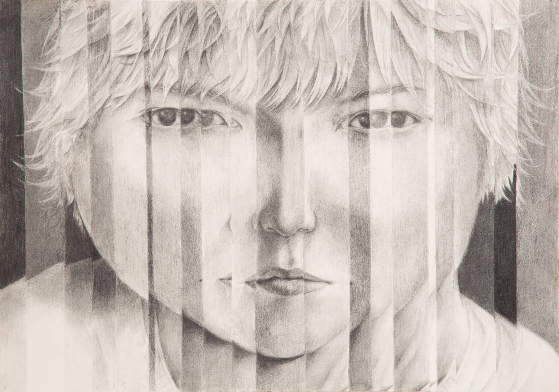
I, for one, am not much of an artist. I hate having to draw specific lines and shape because I am always bad at details. That is why for this assignment, I decided to get creative with what a “face” is. As the assignment directions describe, I decided to stay far away from a realistic face and focus more on practicing what I can do with p5js. The motive for this portrait is this picture:
a self portrait through a shattered glass. Unfortunately, I don’t have the artistic skills, nor coding skills to replicate this painting on p5js, so I decided to use simple shapes and arcs to recreate my own self portrait.
Making Process
I didn’t have a full picture of what I was going to make from the beginning so it was very much coming up with new ideas as I working. Initially, I split the canvas with rectangles using a for loop and then I thought I could use this different sections as a gradation of colors so I set the color fill variable with the iterator in order to achieve that. Since the canvas was split in 12 different rectangles, I created an array of size 12 and use the iterator to find the color value stored in the array to make gradually changing color scheme. Then I built the face structure using the arc element also using the for loop I set for creating the split in the canvas. One issue with this method however, is that each arc from the four sections (x < 250 & y < 250, x > 250 & y < 250, x < 250 & y > 250, x > 250 & y > 250) are all identical. While it does look haphazard because of this, I decided to leave it like this because a) for this assignment I focused more on getting used to p5js so I wanted to keep the for loop iteration in my drawing, b) this had an unintended modern art sensation which I thought was cool. So since I got this modern art looking progress going on, I decided to stick with that theme and incorporate simple shapes to represent my facial features: circles for eyes, triangle for nose, and an arc for my mouth. When I was done with the facial features, I realized that the result looked a little too simple. So to spice things up, I decided to make the facial features move which leads to the next section of my documentation.
Challenge
Turns out, making shapes move in certain behavior on the canvas was much more difficult than I expected. My initial assumption on how to make this work was to make a variable for the x and y position parameters and increase or decrease them. However, when I quickly learned that the shapes didn’t move as I suspected, I had go through a lot of trial and error to try to fix the bugs and get what I wanted. After time, I managed to fix the nose and mouth motion using a speed variable that would be added to the x and y position parameters. If the shape position would reach the left/right or top/bottom end, the speed variable would be multiplied by -1 so the shape motion would go opposite direction and loop so that it would move consistently. The real challenge, however, was the eye motion going in circles. For this one, I couldn’t figure out how to have a shape move in circles, so I did some research. Thankfully, I found a source code online that managed to make this happen
so I referred to this code and learned the sin() function and cos() function with an increasing angle variable according to radian to make a shape move in circle.
let x1 = 225 + 25 * sin(angle);
let y1 = 200 + 25 * cos(angle);
let x2 = 325 + 40 * cos(angle);
let y2 = 150 + 40 * sin(angle);

circle(x1,y1, 50);
circle(x2,y2, 50);

angle += 0.0314;
Wrapping Up
After the challenging parts, I decided to add some sprinkles on the product like changing up the stroke colors and the weight or make a warming up in color gimmick using the angle variable I set for the circle motion. For colors, I knew I wanted to use red, green, and blue because they are the RGB (I know its cheesy but still I thought it was cool). For the color in the background being blue was pure coincidence after playing with the gradation effect so I was left with red and green which each became the color for the nose and the mouth. For the eye color being yellow, I just thought it was a nice color match.
Reflection
Looking back on working on this assignment, I was able to use some of the the basic coding knowledge that I knew beforehand such as conditions, iteration, arrays, etc.. but I also learned a lot about p5js coding environment and its unique functions like how the draw() function behaves or the shape elements. Through this assignment I was reminded a lot about processing which I learned in my freshman year in Intro to CS. As for future possible improvements, I know for sure my code is a hot mess with no comments, very haphazardly organized, and not the most efficient so I hope to be able to code a little more cleanly and in a better way next time, and also learn & utilize more of what p5js can offer.
I learned the basic concepts of p5.js, such as circles, ellipses, and colors, through online tutorials, practice coding, and experimentation. I started out by learning how to create basic shapes using the ellipse and circle functions and then moved on to manipulating more complex shapes such as hair and eyes. I then experimented with different colors to create a more life–like image. After mastering the basics, I began to understand how to use conditionals to create an animation. I then began to experiment with different speeds and directions to create a more dynamic animation. With each new concept I learned, I was able to create a more realistic self–portrait that accurately captures my personality.
This p5.js code is a moving self–portrait of me. It is a creative piece of code that uses mathematical concepts such as conditionals, variables, and geometry to create an animation. The code is comprised of a setup and draw function and uses variables for the coordinates, directions, and speed of the animation. The setup function creates a canvas of 400x400 pixels and sets the starting positions and speeds of the animation. The draw function uses the variables to draw the self-portrait, which consists of a head with eyes, hair, a nose, and a tongue. The head will move from side to side and bounce up and down when it hits the boundaries. This code captures my playful and creative spirit, as it animates me in a unique and amusing way.
The part of the code that I am most proud of is the part of moving and boundary detection. I was able to connect all pieces of the face into one variable so that all of them move simultaneously. Also, the ternary operator is my way of showing my CS skills(jk).
Reflecting on this project, I am proud of my progress and the creative outcome of the code. I am now confident in my ability to use the fundamental concepts of p5.js to create engaging visuals. However, I am also aware that there is still room for improvement and further exploration. I plan to add user interaction to the animation, for example, allowing users to move the portrait with their mouse. Additionally, I would like to incorporate video sensors to create a more life–like animation. This could be achieved by tracking a user’s facial movements and incorporating them into the animation. As I continue to explore the limitless possibilities of p5.js, I look forward to creating increasingly complex animations and engaging interactive experiences.
For this assignment, we were to use p5js online editor to create a self portrait. It did seem like a daunting task, given my incompetence in art and drawings. However, as I played around with the code and different shapes, I put together my face and some of its traits to the best of my ability.
Creating Me
Starting with a blank canvas, I divided the project into various parts to compartmentalise my work. This allowed me to focus on one aspect of the project at time. I created functions to draw different parts of my portrait, which would provide a modular structure to the code as well as help me slowly develop my portrait.
Note: The drawFace() function draws every element in my face.
I started with the outline of my face. Since, my face is oval-shaped, I opted to using an ellipse to achieve this. The parameters I used to make the outline of my face (ellipse) would later be used in every other shapes and objects. In order to achieve this, I made the parameters for the ellipse global variables by declaring them at the top of the code outside any function. I initialised their values inside the setup() function since it would only be run once. I use this global variables as such:
let f_x, f_y;

function setup() {
  createCanvas(500, 500);
  f_x = width/2;
  f_y = height/2 - 40;

  textSize(30);
  textAlign(CENTER, CENTER);
}
f_x and f_y refer to face x-coordinate and face y-coordinate respectively. All the shapes in the portrait is drawn with respect to these variables. In other words, the shapes are drawn with positions corresponding to some manipulation of the aforementioned global variables. Here is an example:
The above code snippet creates the two eyes. Notice that the positions of the ellipses uses f_x and f_y. Basing all the shapes in my portrait, I created a digital image of myself.
Notable Traits:
Straw Hat: The hat is inspired by one of my favourite fictional characters, Monkey D. Luffy.
Rosy Cheeks: I have perpetually red cheeks. Although its shape is not exactly an ellipse, making it an ellipse was the only way it did not look off.
Shadows: The shadow of my head on the neck was made by duplicating the head ellipse and translating it down. The width of the ellipse was then adjusted.
Future Improvements
While I was making my portrait, I noticed that making it dynamic was a challenge. The creation and implementation of global variables, f_x and f_y, did make it sort of dynamic as the portrait would still be intact even if we change the size of the canvas, it would be more dynamic if the shapes would also change size with respect to the canvas. This is something that I could work on to improve the customisability of the portrait.
This entire journey starst with me almost losing an eyeI was in the hospital due to an eye operation procedure that presented personal, medical, and academic circumstances I did not expect. After healing and returning home, my family and I had to go to our Emirate, Fujairah. As a result, I found myself without the Arduino kit we were given in class, but instead, a smaller one that I previously had when teaching myself coding throughout the summer. The Arduino kit did not have all of the equipment that a complete kit would offer but only included a potentiometer, a couple of wires, two buttons, a couple of resistors, and a Liquid Display Screen. Yet, rather than being demotivated and giving up, I took this as an opportunity to explore coding on the LCD!
This opened new doors allowing me to have more than one medium to display imagery. I ended up utilizing this by having the breadboard double as both a controller and a screen while the p5.js sketch is presented as a ‘game state’ indicator. Like all projects I have worked on throughout this course, I wanted to add an artistic element, so I ended up drawing all illustrations presented on p5.js to provide a sense of attraction to the user.
I wish I could have presented this during the IM showcase, as I would have loved to make it a competitive game where the highest score would win a prize and, as a result, attract more people. Nevertheless, despite the limitations and circumstances, I am happy with how the project turned out. I have attached the assets, code (including references), and demonstration video below (presenting the game from a stranger’s perspective).
code:
(code that is altered and commented is due to an Arduino update that messed around with the code. Please reach out if you have any questions)
                            // HAMAD ALSHAMSI

                      // RUN OR DONE: FINAL PROJECT


                                // code


// const int buttonPin = 2; // pin for the button
// int buttonState = 0; // variable to store the button state

// void setup() {
//   pinMode(buttonPin, INPUT); // set the button pin as an input
//   Serial.begin(9600); // start the serial connection
// }

// void loop() {
//   buttonState = digitalRead(buttonPin); // read the button state

//   // if the button is pressed, send a "1" over the serial connection
//   if (buttonState == HIGH) {
//     Serial.println("1");
//   }

//   delay(100); // delay to prevent sending too many "1"s
// }


//allow the incorporation of the LCD for the project
#include <LiquidCrystal.h>

//indicate used pin variables
#define pinPress 2
#define pinPlay 1
#define pinWriteNRead 10
#define pinBrightness 12

//indicate variables for game animations used
#define runAnimation1 1
#define runAnimation2 2
#define jumpAnimation 3
#define topJumpAnimation '.'
#define bottomJumpAnimation 4
#define noObstacleAnimation ' '
#define yesObstacleAnimation 5
#define yesRightObstacleAnimation 6
#define yesLeftObstacleAnimation 7

//fix position for character
#define characterPosition 1
//define obstacle attributes
#define obstacleYSize 16
#define obstacleBlank 0
#define obstacleBottom 1
#define obstacleTop 2
//define character running attributes and poses when on floor
#define characterLocationNul 0
#define characterLocationBottom1 1
#define characterLocationBottom2 2
//define character hopping attributes and poses
#define characterLocationHop1 3
#define characterLocationHop2 4
#define characterLocationHop3 5
#define characterLocationHop4 6
#define characterLocationHop5 7
#define characterLocationHop6 8
#define characterLocationHop7 9
#define characterLocationHop8 10
//define character running attributes and poses when on obstacle
#define characterLocationRunTop1 11
#define characterLocationRunTop2 12

//LCD attributes and pixel arrangement inspired from Rees5286 on YouTube
LiquidCrystal lcd(11, 9, 6, 5, 4, 3);
static char obstaclePresentTop[obstacleYSize + 1];
static char obstaclePresentBottom[obstacleYSize + 1];
static bool pushButton = false;

//assign specific pixels to light up for corresponding poses
void drawCanvasNPixels(){
  static byte canvasNPixels[] = {
    //first running pose
    B01100,
    B01100,
    B00000,
    B01110,
    B11100,
    B01100,
    B11010,
    B10011,
    //second running pose
    B01100,
    B01100,
    B00000,
    B01100,
    B01100,
    B01100,
    B01100,
    B01110,
    //high hop
    B01100,
    B01100,
    B00000,
    B11110,
    B01101,
    B11111,
    B10000,
    B00000,
    //low hop
    B11110,
    B01101,
    B11111,
    B10000,
    B00000,
    B00000,
    B00000,
    B00000,
    //on ground
    B11111,
    B11111,
    B11111,
    B11111,
    B11111,
    B11111,
    B11111,
    B11111,
    //right side on ground
    B00011,
    B00011,
    B00011,
    B00011,
    B00011,
    B00011,
    B00011,
    B00011,
    //left side on ground
    B11000,
    B11000,
    B11000,
    B11000,
    B11000,
    B11000,
    B11000,
    B11000,
  };

  int i;
  //code, referenced from AymaanRahman on YouTube, to skip using '0' and allow rapid character alterations
  for (i = 0; i < 7; ++i) {
      lcd.createChar(i + 1, &canvasNPixels[i * 8]);
  }
  for (i = 0; i < obstacleYSize; ++i) {
    obstaclePresentTop[i] = noObstacleAnimation;
    obstaclePresentBottom[i] = noObstacleAnimation;
  }
}

//move obstacle
void generateObstacles(char* obstacle, byte newObstacle){
  for (int i = 0; i < obstacleYSize; ++i) {
    char current = obstacle[i];
    char next = (i == obstacleYSize-1) ? newObstacle : obstacle[i+1];
    switch (current){
      case noObstacleAnimation:
        obstacle[i] = (next == yesObstacleAnimation) ? yesRightObstacleAnimation : noObstacleAnimation;
        break;
      case yesObstacleAnimation:
        obstacle[i] = (next == noObstacleAnimation) ? yesLeftObstacleAnimation : yesObstacleAnimation;
        break;
      case yesRightObstacleAnimation:
        obstacle[i] = yesObstacleAnimation;
        break;
      case yesLeftObstacleAnimation:
        obstacle[i] = noObstacleAnimation;
        break;
    }
  }
}

//move character
bool characterDraw(byte position, char* obstaclePresentTop, char* obstaclePresentBottom, unsigned int score) {
  bool collision = false;
  char topStore = obstaclePresentTop[characterPosition];
  char bottomStore = obstaclePresentBottom[characterPosition];
  byte top, bottom;
  switch (position) {
    case characterLocationNul:
      top = bottom = noObstacleAnimation;
      break;
    case characterLocationBottom1:
      top = noObstacleAnimation;
      bottom = runAnimation1;
      break;
    case characterLocationBottom2:
      top = noObstacleAnimation;
      bottom = runAnimation2;
      break;
    case characterLocationHop1:
    case characterLocationHop8:
      top = noObstacleAnimation;
      bottom = jumpAnimation;
      break;
    case characterLocationHop2:
    case characterLocationHop7:
      top = topJumpAnimation;
      bottom = bottomJumpAnimation;
      break;
    case characterLocationHop3:
    case characterLocationHop4:
    case characterLocationHop5:
    case characterLocationHop6:
      top = jumpAnimation;
      bottom = noObstacleAnimation;
      break;
    case characterLocationRunTop1:
      top = runAnimation1;
      bottom = noObstacleAnimation;
      break;
    case characterLocationRunTop2:
      top = runAnimation2;
      bottom = noObstacleAnimation;
      break;
  }
  if (top != ' ') {
    obstaclePresentTop[characterPosition] = top;
    collision = (topStore == noObstacleAnimation) ? false : true;
  }
  if (bottom != ' ') {
    obstaclePresentBottom[characterPosition] = bottom;
    collision |= (bottomStore == noObstacleAnimation) ? false : true;
  }

  byte digits = (score > 9999) ? 5 : (score > 999) ? 4 : (score > 99) ? 3 : (score > 9) ? 2 : 1;

  //create canvas for game
  obstaclePresentTop[obstacleYSize] = '\0';
  obstaclePresentBottom[obstacleYSize] = '\0';
  char temp = obstaclePresentTop[16-digits];
  obstaclePresentTop[16-digits] = '\0';
  lcd.setCursor(0,0);
  lcd.print(obstaclePresentTop);
  obstaclePresentTop[16-digits] = temp;
  lcd.setCursor(0,1);
  lcd.print(obstaclePresentBottom);

  lcd.setCursor(16 - digits,0);
  lcd.print(score);

  obstaclePresentTop[characterPosition] = topStore;
  obstaclePresentBottom[characterPosition] = bottomStore;
  return collision;
}

//take in digital button signal
void buttonPush() {
  pushButton = true;
}

//allow the button to act as an interruption to make the character hop
void setup(){
  pinMode(pinWriteNRead, OUTPUT);
  digitalWrite(pinWriteNRead, LOW);
  pinMode(pinBrightness, OUTPUT);
  digitalWrite(pinBrightness, LOW);
  pinMode(pinPress, INPUT);
  digitalWrite(pinPress, HIGH);
  pinMode(pinPlay, OUTPUT);
  digitalWrite(pinPlay, HIGH);
  attachInterrupt(0/*pinPress*/, buttonPush, FALLING);
  drawCanvasNPixels();
  lcd.begin(16, 2);
}

//constantly check for new obstacle generation
void loop(){
  static byte characterLoc = characterLocationBottom1;
  static byte newObstacleType = obstacleBlank;
  static byte newObstacleDuration = 1;
  static bool playing = false;
  static bool blink = false;
  static unsigned int distance = 0;

  if (!playing) {
    characterDraw((blink) ? characterLocationNul : characterLoc, obstaclePresentTop, obstaclePresentBottom, distance >> 3);
    if (blink) {
      lcd.setCursor(0,0);
      lcd.print("Press Start");
    }
    delay(250);
    blink = !blink;
    if (pushButton) {
      drawCanvasNPixels();
      characterLoc = characterLocationBottom1;
      playing = true;
      pushButton = false;
      distance = 0;
    }
    return;
  }

  //constantly move obstacles towards the character
  generateObstacles(obstaclePresentBottom, newObstacleType == obstacleBottom ? yesObstacleAnimation : noObstacleAnimation);
  generateObstacles(obstaclePresentTop, newObstacleType == obstacleTop ? yesObstacleAnimation : noObstacleAnimation);

  //create obstacle repeatedly
  if (--newObstacleDuration == 0) {
    if (newObstacleType == obstacleBlank) {
      newObstacleType = (random(3) == 0) ? obstacleTop : obstacleBottom;
      newObstacleDuration = 2 + random(10);
    } else {
      newObstacleType = obstacleBlank;
      newObstacleDuration = 10 + random(10);
    }
  }

  //allow character to jump if interruption senses
  if (pushButton) {
    if (characterLoc <= characterLocationBottom2) characterLoc = characterLocationHop1;
    pushButton = false;
  }

//constantly check if character is in collision, if so game ends
  if (characterDraw(characterLoc, obstaclePresentTop, obstaclePresentBottom, distance >> 3)) {
    playing = false;
  } else {
    if (characterLoc == characterLocationBottom2 || characterLoc == characterLocationHop8) {
      characterLoc = characterLocationBottom1;
    } else if ((characterLoc >= characterLocationHop3 && characterLoc <= characterLocationHop5) && obstaclePresentBottom[characterPosition] != noObstacleAnimation) {
      characterLoc = characterLocationRunTop1;
    } else if (characterLoc >= characterLocationRunTop1 && obstaclePresentBottom[characterPosition] == noObstacleAnimation) {
      characterLoc = characterLocationHop5;
    } else if (characterLoc == characterLocationRunTop2) {
      characterLoc = characterLocationRunTop1;
    } else {
      ++characterLoc;
    }
    ++distance;

    digitalWrite(pinPlay, obstaclePresentBottom[characterPosition + 2] == noObstacleAnimation ? HIGH : LOW);
  }
  delay(100);
}


                                      // references

//inspired projects
//https://www.youtube.com/@rees5286
//https://rishanda.github.io/BSE_Template_Portfolio/

//learning how to incorporate LCD in project
//https://www.youtube.com/watch?v=EAeuxjtkumM&ab_channel=AymaanRahman
//https://www.youtube.com/watch?v=dZZynJLmTn8&ab_channel=HowToMechatronics
During this week’s assignment, we were required to use Arduino by experimenting with a way to construct a hands-free switch (one that does not require an included analog/digital switch). Approaching this assignment, I had intentions of utilizing the Arduino in a way that would be beneficial.
code:
// Define pin for buzzer
const int buzzerPin = 9;

// Define alarm time in hours and minutes
const int alarmHour = 7;
const int alarmMinute = 30;

void setup() {
  // Set the buzzer pin as an output
  pinMode(buzzerPin, OUTPUT);
}

void loop() {
  // Get the current time
  int currentHour = hour();
  int currentMinute = minute();

  // Check if it is time for the alarm
  if (currentHour == alarmHour && currentMinute == alarmMinute) {
    // Turn on the buzzer
    digitalWrite(buzzerPin, HIGH);
    delay(1000);
    // Turn off the buzzer
    digitalWrite(buzzerPin, LOW);
    delay(1000);
  }
}
method:
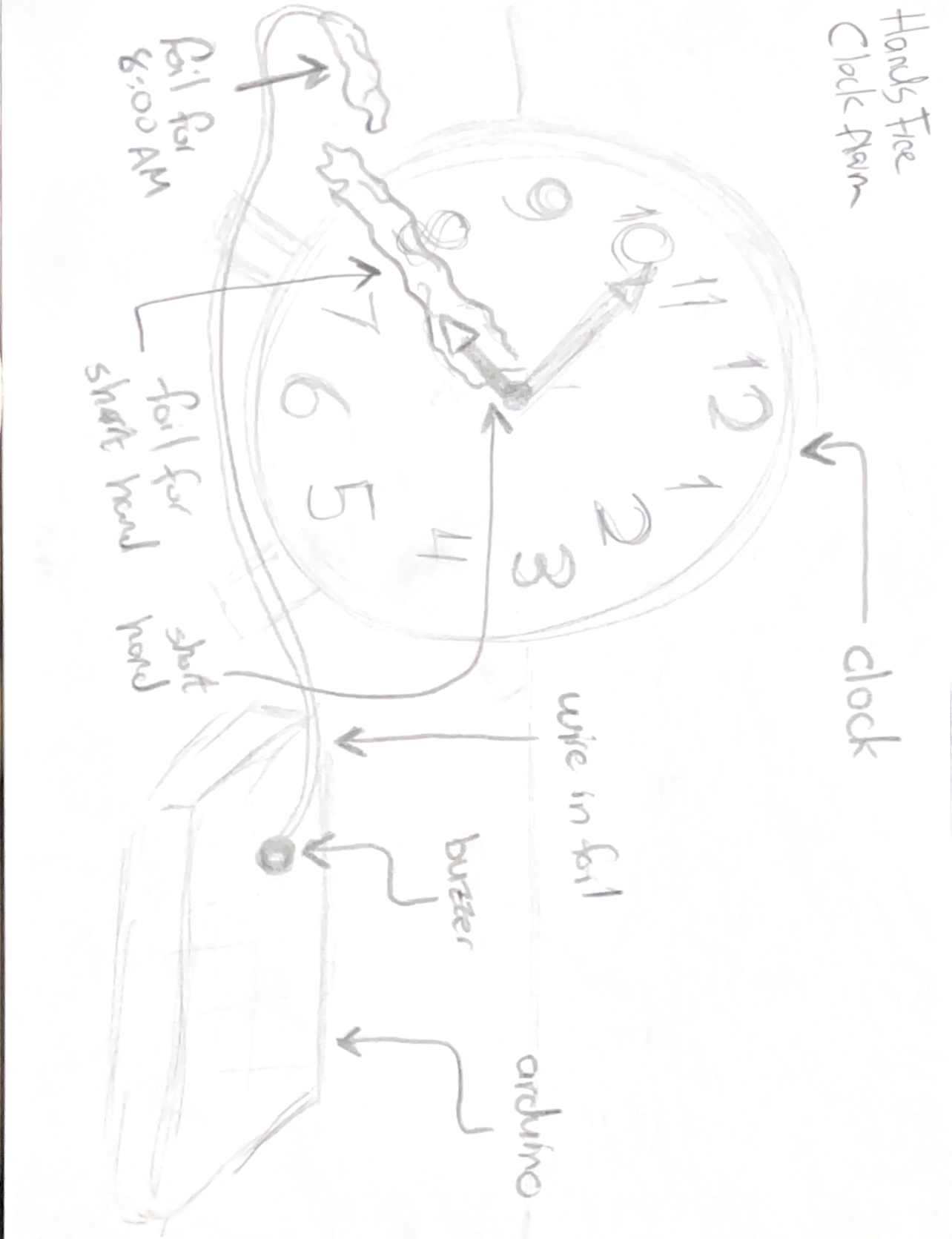
Throughout the 12th week of the semester, another Interactive Media course, Communication and Technology, required us to experiment with going through a digital detox. As a result, I faced the issue of not being able to wake myself up since I ultimately pushed my phone away from me. That being said, I found this assignment perfect as I could make my own digital clock while also including the “hands-free” concept. The hands-free aspect was to add foil to an alarm clock’s hour hand to recognize when it hits a specific hour. This is displayed in the illustration below. To further utilize this, I adapted a simple alarm clock script that exerts a sound as soon as the signal is detected, requiring the person to wake up and pull the foil until they have to place it on again before sleeping.
sketch:
The hands-free element is when the hour arm of the clock moves to 8:00AM and eventually makes contact with the other foil piece that houses the wire connected to the Arduino, further turning on the buzzer.
future improvements:
Possibly present an element that would automatically replace the foil after it is removed to prevent further redundancy.
Initially, we wanted to create a simple art project using multiple servos to control panels. That was very short-lived. Our concept slowly went from a simple interactive art piece that looked pretty to an interactive monster called a Demogorgon from the Netflix series Stranger Things. We wanted to make something interesting that could catch users’ attention longer than an art piece. Since our Demogorgon was not going to necessarily be a game with a winning or losing outcome, we still had to figure out ways to make it more interactive. We took our assigned reading: Emotion & Design: Attractive Things Work Better by Don Norman into consideration and decided that in order to convey what we wanted we needed to make the Demogorgon come to life and make it something that is interesting to look at in addition to the code and interact itive component. To make both the interactive component and the Demogorgon fit nicely together, we decided to use certain scenes of the show to inspire the movements. In the show, the protagonist Eleven defeats a Demogorgon by putting her hand up since she has the ability to manipulate living beings however she wants through her hands. This inspired us to make it so the user is able to open the Demogorgon face flaps we build as their hand gets closer to them through a distance-measuring sensor. As we went along with our project, we realized how ambitious we were with our concept and simply tried our best to make it happen.
For our project, we used the ultrasonic distance measuring sensors, LED lights, flex sensors, 3-d printing, cardboard, wood, acrylic, and paint. Though we went through a lot of hiccups including but not limited to spending hours soldering cables we ended up not using, one of us going into isolation because of COVID-19, short circuits, and re-thinking our concept a few times… we kind of did it.
Interaction Design
Physical
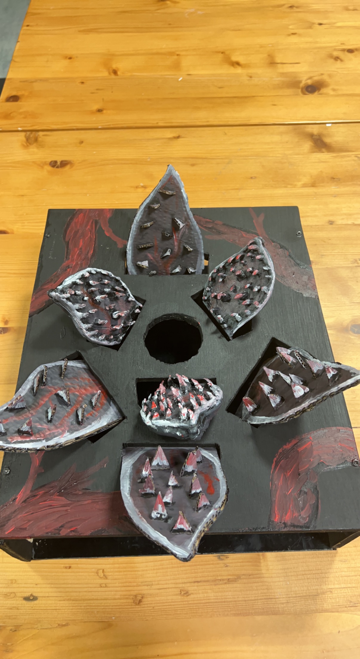
This was a very time-consuming aspect of project, especially since we really wanted it to make look as much as a Demogorgon’s head as possible with what we had. The wood that was available to us was pretty thick and we knew we had to cut holes in it to make openings for the 3-d printed and handmade Demogorgon flaps so it was going to take a long time to cut the wood and put everything together. Luckily, the woodshop was nice enough to let us borrow a Jigsaw so even though it was still a tedious process of drilling two holes where we wanted one hole for the flap to be and then using the Jigsaw to go in and follow the outline, it made it go a lot faster. We did this process seven times. For the flaps of the Demogorgon, at first, we 3-d printed three of them but it was taking a long time so for the last four we decided to build them out of cardboard for time’s sake. The 3-d printed ones still looked pretty cool though and definitely added an appeal to it, in our opinion. Plus, the different materials fit the Demogorgon vibe. We painted and added red and white for the skin tone. We also had to make longer cables to reach the Demogorgon flaps when our Arduino port is hidden beneath the box/head.
Arduino Code
Our Arduino code controlled the flex sensors, server motors, and ultrasonic measuring sensor. The sens0rs were mapped to values from 0 to 180 and then output at different rates depending upon the configuration. The output rates helped stabilize the servo motors which were prone to jittering.
// Clears the trigPin condition
digitalWrite(trigPin, LOW);
delayMicroseconds(100);
// Sets the trigPin HIGH (ACTIVE) for 10 microseconds
digitalWrite(trigPin, HIGH);
delayMicroseconds(100);
digitalWrite(trigPin, LOW);
// Reads the echoPin, returns the sound wave travel time in microseconds
duration = pulseIn(echoPin, HIGH);
// Calculating the distance
distance = duration * 0.034 / 2; // Speed of sound wave divided by 2 (go and back)
// Displays the distance on the Serial Monitor
distanceMapped = map(distance, 0, 70, 22, 180);
distanceMapped=constrain(distanceMapped, 30, 180); //this allows the output to stay between the constraints. without this it goes up to like a few thousand for some reason

int distanceMappedforOuter = distanceMapped + 10; // the outer petals will open wider, to give a flared look

myOuterServos.write(distanceMappedforOuter);
delay(75);
myInnerServos.write(distanceMapped);
delay (75);
Code to control servos with the Flex Sensors:
int OutsideFlexValue;
int InnerFlexValue;

int servoPositionInside;
int servoPositionOutside;

OutsideFlexValue = analogRead(OutsideFlexPin);
// delay(15); //adding slight delays to make it stable

InnerFlexValue = analogRead(InsideFlexPin);
// delay(15);

servoPositionOutside = map(OutsideFlexValue, 170, 500, 0, 180); // need it to rest at a midwards position
servoPositionOutside = constrain(servoPositionOutside, 0, 180);
// int round10(int servoPositionOutside);

servoPositionInside = map(InnerFlexValue, 100, 360, 0, 180);
servoPositionInside = constrain(servoPositionInside, 0, 180);

// servoPosition = constrain(servoPosition, 45, 180); //for the servos that go beyond 180

myOuterServos.write(servoPositionOutside);
delay(75);
myInnerServos.write(servoPositionInside);
delay(75);
To reduce jittering the following line of code was added to constrain the servo motors from going beyond set parameters.
distanceMapped = map(distance, 0, 70, 22, 180);
distanceMapped=constrain(distanceMapped, 30, 180); //this allows the output to stay between the constraints. without this it goes up to like a few thousand for some reason
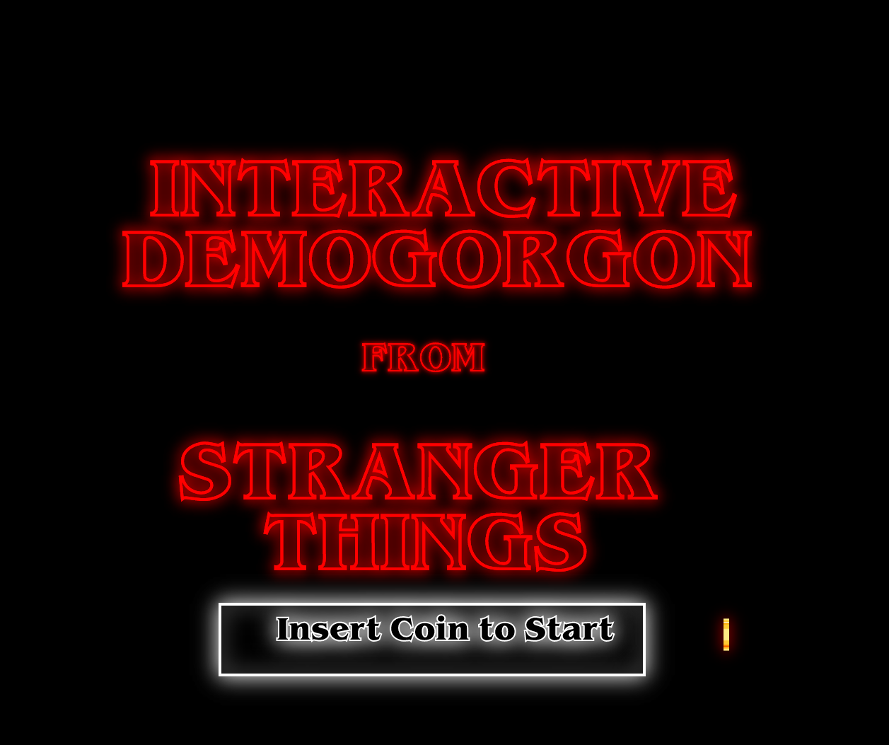
p5.js Code
Our p5.js code focused on the screen that the user would see and use to interact with our Demogorgon. We used the game state and included a starting screen followed by an introduction and instruction screen. We realize not everyone may know what a Demogorgon is or have watched Stranger Things, so we made it feel an arcade game you would go up to, get an introduction and instructions for, and start playing around with it whether or not you fully grasp the inspiration behind it.
There was an issue that we couldn’t quite figure out. After adding the second sound, the audio would start glitching after a while. At first, we thought it was just the sound so we tried it out with different sounds but no luck. When we decided to search if there was a solution or if the code was wrong, we found a thread from 2020 that discussed how the newest versions of p5.js have audible distorted effects on Chrome and there is no fix yet. The audio just keeps getting distorted and eventually the window shuts down and you have to refresh the page.
The p5js code can be accessed on Abigail and I’s p5js sketches directory on the p5js website.
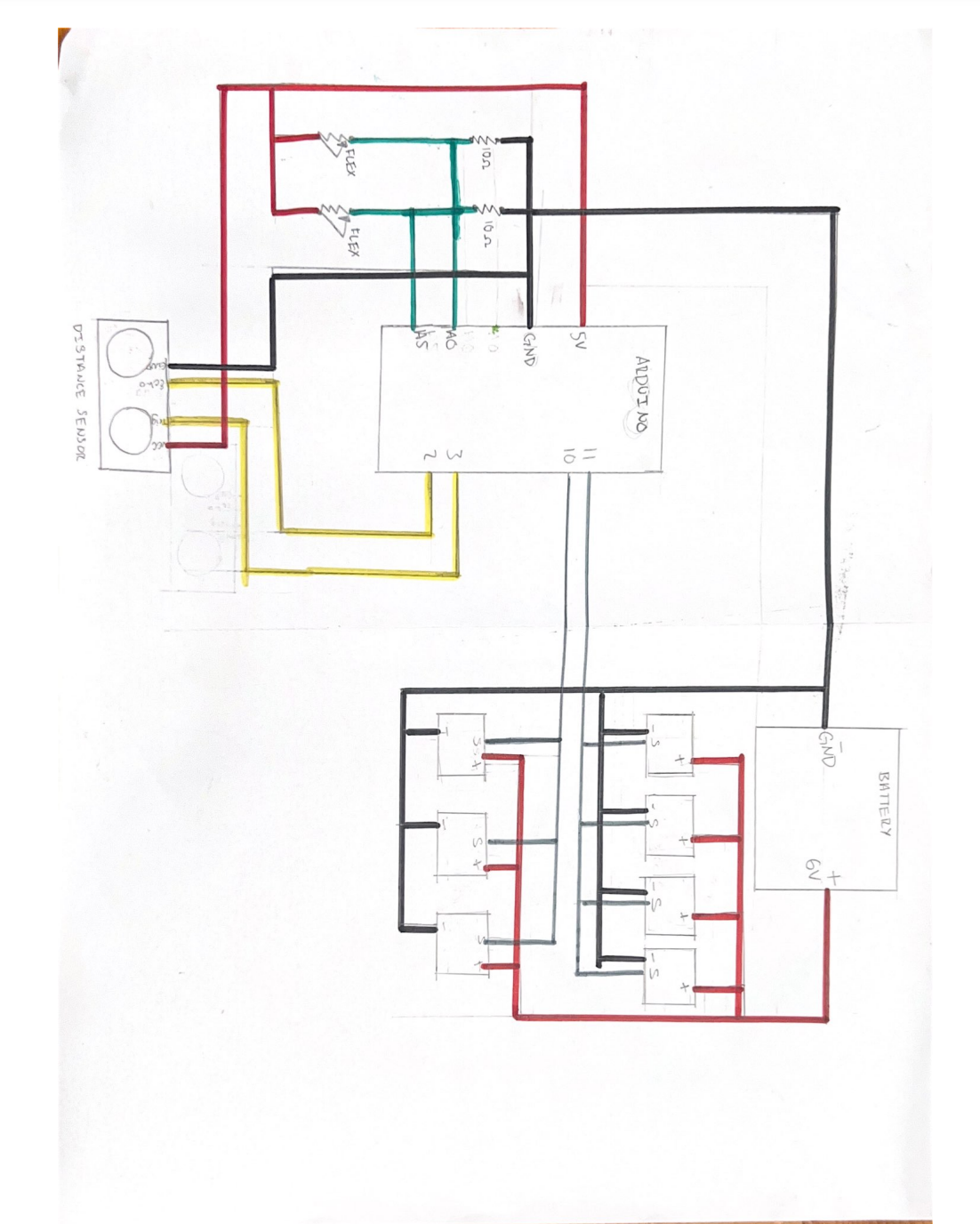
Circuit Diagram for the Project:
Since our project was rather complicated and needed a lot of cables, we decided to draw a schematic for it.
Problem(s) 🙁
Though we knew what needed to be communicated between the Arduino and p5.js, it worked only sometimes. The problems started when we started off by checking out the Arduino MEGA from the IM Lab and tailoring our code to it. However, since we got an extension past the last day to return items to the IM Lab due to reasons neither of us could control, we had to switch back to the Arduino we received in our kit. For some reason what we had did not work after that and we had to figure out why. We switched up the code again but only some parts of it would work and only sometimes as p5.js kept shutting down and the serial connection kept disconnecting. We tried to ask for help through friends and Facebook groups. No one was able to help us though and as we ran out of time we accepted our fate. The Demogorgon beat us (sorta).
Some testing and progress videos:
Testing the Flex sensors interfaced with the servo motors:
Testing the ultrasonic distance sensor interfaced with the servos:
Problems that we ran into and how we tried to solve them:
The first problem we ran into pretty early on was a jittering in the servo motors that could not be controlled. The jittering would make the servos move even when the code was not running. After some debugging, we realized that the problem originated with the 5v supply on the main board, and switching the servos to an external power source would reduce it. It could be made smoother by adding another earth wire connected to one of the unused GND pins
Another problem we ran into was the 3d printing of some of the parts. The models we had used were pulled off the internet and were supposed to be printed within a few hours but the first 3 iterations were all just a mess of melted filament since the model would move around. After consulting the lab assistants we realized scraping the surface of the building area of the printer solved the issue immediately.
A bug that we ran into while working on the Arduino-p5js serial communication was that the communication would halt and spout an error ‘Failed to open serial port’. We realized that this could be fixed most of the time by closing the serial monitor on the IDE. However, at one point it persisted despite restarting, and according to some forums, it was a problem with incompatible drivers that plague computers with versions of windows later than 10.
Another bug that we ran across that caused us the most trouble was that the p5js terminal would not work or crash periodically after adding sound effects that were to be played on the terminal. We could not find a viable solution for this problem.
Future Improvements:
I think we focused on Professor’s warning that the physical component was going to take a really long time too much. Our concept depended a lot on being appealing to the audience so we wanted to make sure we made our Demogorgon look really good and spooky. However, I think we spent so much time on it considering the limited time we had that we did not think about how buggy the code would be considering everything we were trying to make it do at once.
Figure out a more stable way for communication between p5js and Arduino.
Use a stable operating system that causes least amounts of problems with regards to drivers
Use a stable search engine to run p5js smoothly
Reflection:
Overall, this project was an interesting one for us. I never would have thought that I would attempt to do something like this when I started this class. I am very proud of our physical component, our creativity, and our perseverance despite the non-stop obstacles that kept coming our way whether they were from our code or life events.
I was able to build the physical component, cutting everything with the jigsaw, putting it together, initiated the 3-d printing process, and painted it. I was actually very proud of myself for getting my hands dirty with the jigsaw and being able to use it. It felt good to use my hands to build something instead of beating my brain into figuring out code. I also drew the schematic and helped build most of the p5.js code. I soldered all of the server motor cables together to make them reach our Demogorgon and made sure to take pictures of our progress throughout the time we were working on the project.
Though I never learned to like coding while taking this class, it was definitely a learning experience. When I did get things on my own and processed what was going on, it felt really rewarding! This class was very different than what I am used to but I very much enjoyed learning something other than Political Science and Law. It was a great class and it was amazing seeing what my classmates who know this stuff well build and code.
Initially, we wanted to create a simple art project using multiple servos to control panels. That was very short-lived. Our concept slowly went from a simple interactive art piece that looked pretty to an interactive monster called a Demogorgon from the Netflix series Stranger Things. We wanted to make something interesting that could catch users’ attention longer than an art piece. Since our Demogorgon was not going to necessarily be a game with a winning or losing outcome, we still had to figure out ways to make it more interactive. We took our assigned reading: Emotion & Design: Attractive Things Work Better by Don Norman into consideration and decided that in order to convey what we wanted we needed to make the Demogorgon come to life and make it something that is interesting to look at in addition to the code and interact itive component. To make both the interactive component and the Demogorgon fit nicely together, we decided to use certain scenes of the show to inspire the movements. In the show, the protagonist Eleven defeats a Demogorgon by putting her hand up since she has the ability to manipulate living beings however she wants through her hands. This inspired us to make it so the user is able to open the Demogorgon face flaps we build as their hand gets closer to them through a distance-measuring sensor. As we went along with our project, we realized how ambitious we were with our concept and simply tried our best to make it happen.
For our project, we used the ultrasonic distance measuring sensors, LED lights, flex sensors, 3-d printing, cardboard, wood, acrylic, and paint. Though we went through a lot of hiccups including but not limited to spending hours soldering cables we ended up not using, one of us going into isolation because of COVID-19, short circuits, and re-thinking our concept a few times… we kind of did it.
Interaction Design
Physical
This was a very time-consuming aspect of project, especially since we really wanted it to make look as much as a Demogorgon’s head as possible with what we had. The wood that was available to us was pretty thick and we knew we had to cut holes in it to make openings for the 3-d printed and handmade Demogorgon flaps so it was going to take a long time to cut the wood and put everything together. Luckily, the woodshop was nice enough to let us borrow a Jigsaw so even though it was still a tedious process of drilling two holes where we wanted one hole for the flap to be and then using the Jigsaw to go in and follow the outline, it made it go a lot faster. We did this process seven times. For the flaps of the Demogorgon, at first, we 3-d printed three of them but it was taking a long time so for the last four we decided to build them out of cardboard for time’s sake. The 3-d printed ones still looked pretty cool though and definitely added an appeal to it, in our opinion. Plus, the different materials fit the Demogorgon vibe. We painted and added red and white for the skin tone. We also had to make longer cables to reach the Demogorgon flaps when our Arduino port is hidden beneath the box/head.
Arduino Code
Our Arduino code controlled the flex sensors, server motors, and ultrasonic measuring sensor. The sens0rs were mapped to values from 0 to 180 and then output at different rates depending upon the configuration. The output rates helped stabilize the servo motors which were prone to jittering.
// Clears the trigPin condition
digitalWrite(trigPin, LOW);
delayMicroseconds(100);
// Sets the trigPin HIGH (ACTIVE) for 10 microseconds
digitalWrite(trigPin, HIGH);
delayMicroseconds(100);
digitalWrite(trigPin, LOW);
// Reads the echoPin, returns the sound wave travel time in microseconds
duration = pulseIn(echoPin, HIGH);
// Calculating the distance
distance = duration * 0.034 / 2; // Speed of sound wave divided by 2 (go and back)
// Displays the distance on the Serial Monitor
distanceMapped = map(distance, 0, 70, 22, 180);
distanceMapped=constrain(distanceMapped, 30, 180); //this allows the output to stay between the constraints. without this it goes up to like a few thousand for some reason

int distanceMappedforOuter = distanceMapped + 10; // the outer petals will open wider, to give a flared look

myOuterServos.write(distanceMappedforOuter);
delay(75);
myInnerServos.write(distanceMapped);
delay (75);
Code to control servos with the Flex Sensors:
int OutsideFlexValue;
int InnerFlexValue;

int servoPositionInside;
int servoPositionOutside;

OutsideFlexValue = analogRead(OutsideFlexPin);
// delay(15); //adding slight delays to make it stable

InnerFlexValue = analogRead(InsideFlexPin);
// delay(15);

servoPositionOutside = map(OutsideFlexValue, 170, 500, 0, 180);  // need it to rest at a midwards position
servoPositionOutside = constrain(servoPositionOutside, 0, 180);
// int round10(int servoPositionOutside);

servoPositionInside = map(InnerFlexValue, 100, 360, 0, 180);
servoPositionInside = constrain(servoPositionInside, 0, 180);

// servoPosition = constrain(servoPosition, 45, 180); //for the servos that go beyond 180

myOuterServos.write(servoPositionOutside);
delay(75);
myInnerServos.write(servoPositionInside);
delay(75);
To reduce jittering the following line of code was added to constrain the servo motors from going beyond set parameters.
distanceMapped = map(distance, 0, 70, 22, 180);
distanceMapped=constrain(distanceMapped, 30, 180); //this allows the output to stay between the constraints. without this it goes up to like a few thousand for some reason
p5.js Code
Our p5.js code focused on the screen that the user would see and use to interact with our Demogorgon. We used the game state and included a starting screen followed by an introduction and instruction screen. We realize not everyone may know what a Demogorgon is or have watched Stranger Things, so we made it feel an arcade game you would go up to, get an introduction and instructions for, and start playing around with it whether or not you fully grasp the inspiration behind it.
There was an issue that we couldn’t quite figure out. After adding the second sound, the audio would start glitching after a while. At first, we thought it was just the sound so we tried it out with different sounds but no luck. When we decided to search if there was a solution or if the code was wrong, we found a thread from 2020 that discussed how the newest versions of p5.js have audible distorted effects on Chrome and there is no fix yet. The audio just keeps getting distorted and eventually the window shuts down and you have to refresh the page.
The p5js code can be accessed on Abigail and I’s p5js sketches directory on the p5js website.
Circuit Diagram for the Project:
Since our project was rather complicated and needed a lot of cables, we decided to draw a schematic for it.
Problem(s) 🙁
Though we knew what needed to be communicated between the Arduino and p5.js, it worked only sometimes. The problems started when we started off by checking out the Arduino MEGA from the IM Lab and tailoring our code to it. However, since we got an extension past the last day to return items to the IM Lab due to reasons neither of us could control, we had to switch back to the Arduino we received in our kit. For some reason what we had did not work after that and we had to figure out why. We switched up the code again but only some parts of it would work and only sometimes as p5.js kept shutting down and the serial connection kept disconnecting. We tried to ask for help through friends and Facebook groups. No one was able to help us though and as we ran out of time we accepted our fate. The Demogorgon beat us (sorta).
Some testing and progress videos:
Testing the Flex sensors interfaced with the servo motors:
Testing the ultrasonic distance sensor interfaced with the servos:
Problems that we ran into and how we tried to solve them:
The first problem we ran into pretty early on was a jittering in the servo motors that could not be controlled. The jittering would make the servos move even when the code was not running. After some debugging, we realized that the problem originated with the 5v supply on the main board, and switching the servos to an external power source would reduce it. It could be made smoother by adding another earth wire connected to one of the unused GND pins
Another problem we ran into was the 3d printing of some of the parts. The models we had used were pulled off the internet and were supposed to be printed within a few hours but the first 3 iterations were all just a mess of melted filament since the model would move around. After consulting the lab assistants we realized scraping the surface of the building area of the printer solved the issue immediately.
A bug that we ran into while working on the Arduino-p5js serial communication was that the communication would halt and spout an error ‘Failed to open serial port’. We realized that this could be fixed most of the time by closing the serial monitor on the IDE. However, at one point it persisted despite restarting, and according to some forums, it was a problem with incompatible drivers that plague computers with versions of Windows later than 10.
Another bug that we ran across that caused us the most trouble was that the p5js terminal would not work or crash periodically after adding sound effects that were to be played on the terminal. We could not find a viable solution to this problem.
We did not realize until the last moment that there were in fact some subtle differences between how Arduino mega and uno work. Other than the size and ram, there is also a difference in how we set up the ultrasonic distance sensor by following this tutorial. There were other differences too that for some reason broke the code when we tried running it on the Uno however we cannot seem to locate the exact piece of code that caused it.
Future Improvements:
I think we focused on Professor’s warning that the physical component was going to take a really long time too much. Our concept depended a lot on being appealing to the audience so we wanted to make sure we made our Demogorgon look really good and spooky. However, we spent so much time on it considering the limited time we had that we did not think about how buggy the code would be considering everything we were trying to make it do at once.
Figure out a more stable way for communication between p5js and Arduino.
Use a stable operating system that causes the least amount of problems with regard to drivers
Use a stable search engine to run p5js smoothly
Employ a better and more rigorous documentation method along the progress of future projects to create a seamless reference system in case of mistakes. We spent way too much time trying to debug without knowing what resources I had accessed before or how we had implemented stuff.
Project Reflection:
This project was really challenging yet somewhat rewarding. I think personally, I would like to spend more time researching the project before actually starting with it. The technique of ‘forcing’ a project or completing it by brute force is not something that can be accomplished with such projects. This project also gave me experience with interfacing Arduino boards with p5js. And showed me how important it is to start early with developing a code that can work seamlessly, especially with tools that are relatively new to me, and are already known to have caused problems.
The project was also an opportunity for me to gain more knowledge and technical know-how from the Professor who has been teaching people about creative robotics for a long time. I was able to pick his brains but failed to capitalize on him as an incredible resource towards the final stretch which led to failure to achieve a favorable final project. It made me realise how important it was to reach out when there is a problem hampering progress.
Moreover, the project allowed me to push my boundaries to the extreme. Not only was it intellectually strenuous, requiring a great amount of technical know-how and problem-solving abilities but also physically straining and intensive. I am extremely disappointed in not being able to assemble the final project in a way that was, well, final. However, this project has only given me more drive to try and learn more about p5js, and Arduino and how these two tools can be merged to create working machines beyond their apparent limits.
This week we learnt that serial communication is a way for devices, like an Arduino microcontroller and a computer, to exchange data. It allows the Arduino to send data to the computer or for the computer to send data to the Arduino.
One way to establish serial communication between an Arduino and a computer is to use p5.js, a JavaScript library for creating interactive graphics and visualizations. To use serial communication with p5.js, we will need to use the p5.serialport library, which is a p5.js library that provides a wrapper around the popular serialport library for Node.js.
Once we have set up the p5.serialport library and created a p5.Serial object, we can use the serial.read() function to read data from the serial port and the serial.write() function to write data to the serial port. We can also use the serial.on() function to set up event listeners for different events, like when data is received or when the serial port is opened or closed.
Exercise 1:
In class we practiced serial communication using a potentiometer example. We modified the potentiometer example demonstrated in class to create a ball that bounces horizontally across the screen at a speed that is determined by the value of the potentiometer. In our Arduino code, we used serial communication to send the value of the potentiometer to the p5.js sketch, which was then used to control the velocity of the bouncing ball:
Arduino Code:
void loop() {
// put your main code here, to run repeatedly:
 int potentiomenter = analogRead(A0);
 int mappedPot = map(potentiomenter, 0, 1023, 0, 255);
 Serial.write(mappedPot);
delay(100);
n our p5.js sketch, we created a ball object using a Circle class with properties for the x and y positions and a move() method. The move() method only updates the x position of the ball, which is calculated using the value of the potentiometer that was read from the Arduino using serial communication. The y position of the ball remains constant along the horizontal axis at the height/2 position. The p5js code for this exercise:
// variable to hold an instance of the p5.webserial library:
const serial = new p5.WebSerial();

// HTML button object:
let portButton;
let inData;                   // for incoming serial data
let outByte = 0;              // for outgoing data

function setup() {
  createCanvas(400, 300);          // make the canvas
  // check to see if serial is available:
  if (!navigator.serial) {
    alert("WebSerial is not supported in this browser. Try Chrome or MS Edge.");
  }
  // if serial is available, add connect/disconnect listeners:
  navigator.serial.addEventListener("connect", portConnect);
  navigator.serial.addEventListener("disconnect", portDisconnect);
  // check for any ports that are available:
  serial.getPorts();
  // if there's no port chosen, choose one:
  serial.on("noport", makePortButton);
  // open whatever port is available:
  serial.on("portavailable", openPort);
  // handle serial errors:
  serial.on("requesterror", portError);
  // handle any incoming serial data:
  serial.on("data", serialEvent);
  serial.on("close", makePortButton);
}

function draw() {

   background(0);
   fill(255);
   text("sensor value: " + inData, 30, 50);

}
// if there's no port selected,
// make a port select button appear:
function makePortButton() {
  // create and position a port chooser button:
  portButton = createButton("choose port");
  portButton.position(10, 10);
  // give the port button a mousepressed handler:
  portButton.mousePressed(choosePort);
}

// make the port selector window appear:
function choosePort() {
  if (portButton) portButton.show();
  serial.requestPort();
}

// open the selected port, and make the port
// button invisible:
function openPort() {
  // wait for the serial.open promise to return,
  // then call the initiateSerial function
  serial.open().then(initiateSerial);

  // once the port opens, let the user know:
  function initiateSerial() {
    console.log("port open");
  }
  // hide the port button once a port is chosen:
  if (portButton) portButton.hide();
}

// pop up an alert if there's a port error:
function portError(err) {
  alert("Serial port error: " + err);
}
// read any incoming data as a string
// (assumes a newline at the end of it):
function serialEvent() {
  inData = Number(serial.read());
  console.log(inData);
}

// try to connect if a new serial port
// gets added (i.e. plugged in via USB):
function portConnect() {
  console.log("port connected");
  serial.getPorts();
}

// if a port is disconnected:
function portDisconnect() {
  serial.close();
  console.log("port disconnected");
}

function closePort() {
  serial.close();
}
Exercise 2:
In our sketch, we created an interactive visual that represents a sun rising and falling in the sky and linked it to the brightness of an LED. When the up arrow key is pressed, the sun “rises” in the sky and the background color changes to a bright magenta. When the down arrow key is pressed, the sun “falls” and the background color deepens to a dark blue. We achieved this effect by using the y position of the sun, which was created using the Circle class from the previous exercise, to control the RGB values of the background color.
Arduino Code:
void setup() {
  Serial.begin(9600);
  pinMode(2, OUTPUT);
  pinMode(5, OUTPUT);
  while (Serial.available() <= 0) {
    Serial.println("0,0"); // send a starting message
    delay(200);
  }
}
void loop() {
  while (Serial.available() > 0) {
    // read the incoming byte:
    int inByte = Serial.read();
    analogWrite(5,inByte);
    Serial.println();
  }
}
p5js Code:
let serialPort; // variable to hold an instance of the serialport library
let portName = "COM3"; // fill in your serial port name here
let currentXPos=0;
let currentYPos=240;
let switchStatus=0;
let value;
function setup() {
createCanvas(640, 480);
serialPort = new p5.SerialPort(); // make a new instance of the serialport library
serialPort.on("list", printListOfPorts); // set a callback function for the serialport list event
serialPort.on("connected", serverConnected); // callback for connecting to the server
serialPort.on("open", portOpened); // callback for the port opening
serialPort.on("data", serialDataReceived); // callback for when new data arrives
serialPort.on("error", serialError); // callback for errors
serialPort.on("close", portClosed); // callback for the port closing
serialPort.list(); // list the serial ports
serialPort.open(portName); // open a serial port
}
function draw() {
background(255);
value = map(mouseX, 0, width, 0, 255);
}
// get the list of ports:
function printListOfPorts(portList) {
// portList is an array of serial port names
for (let i = 0; i < portList.length; i++) {
// Display the list the console:
print(i + " " + portList[i]);
}
}
function serverConnected() {
print("Connected to server.");
}
function portOpened() {
print("The serial port opened.");
}
function serialDataReceived() {
// read a string from the serial port
// until you get carriage return and newline:
let incomingString = serialPort.readLine();
serialPort.write(value);
}
function serialError(err) {
print("Something went wrong with the serial port. " + err);
}
function portClosed() {
print("The serial port closed.");
}
Exercise 3:
For the final assignment, we had to use bidirectional serial communication, which basically involved controlling a p5js sketch with an Arduino and changing the p5js sketch to modify the arduino. We made the ball move on the Arduino by using a distance sensor to modify the wind speed in p5js. Depending on the ball’s velocity, we programmed the p5js sketch so that an LED will turn on each time the ball bounces.
Arduino Code:
Arduino code
void setup() {
  Serial.begin(9600);
  pinMode(2, OUTPUT);
  while (Serial.available() <= 0) {
    Serial.println("0"); // send a starting message
    delay(300);              // wait 1/3 second
  }
}
void loop() {
  while (Serial.available() > 0) {
    // read the incoming byte:
    int inByte = Serial.read();
    analogWrite(2, inByte);
    int WindPower = analogRead(A0);
    Serial.println(WindPower);

  }
}
p5js Code:
let serialPort; // variable to hold an instance of the serialport library
let portName = "COM7"; // replace with your serial port name
let speed;
let weight;
let location;
let acceleration;
let wind;
let resistance = 0.99;
let mass = 50;
let windVal;

function setup() {
createCanvas(640, 360);
noFill();
location = createVector(width/2, 0);
speed = createVector(0,0);
acceleration = createVector(0,0);
weight = createVector(0, 0.5*mass);
wind = createVector(0,0);

serialPort = new p5.SerialPort(); // create a new instance of the serialport library
serialPort.on("list", printPortList); // set a callback function for the serialport list event
serialPort.on("connected", serverConnected); // callback for connecting to the server
serialPort.on("open", portOpen); // callback for the port opening
serialPort.on("data", serialEvent); // callback for when new data arrives
serialPort.on("error", serialError); // callback for errors
serialPort.on("close", portClose); // callback for the port closing
serialPort.list(); // list the serial ports
serialPort.open(portName); // open a serial port
}

// get the list of ports:
function printPortList(portList) {
// portList is an array of serial port names
for (let i = 0; i < portList.length; i++) {
// Display the list the console:
print(i + " " + portList[i]);
}
}

function serverConnected() {
print("Connected to server.");
}

function portOpen() {
print("The serial port opened.");
}

function serialEvent() {
// read a string from the serial port until a carriage return and newline are received
let inString = serialPort.readLine();
print(inString);
if (inString.length > 0){
windVal = map(inString, 0, 1023, -3, 3);
}
}

function serialError(err) {
print("There was an error with the serial port: " + err);
}

function portClose() {
print("The serial port closed.");
}

function draw() {
background(255);

wind.x = windVal;

applyForce(wind);
applyForce(weight);
speed.add(acceleration);
speed.mult(resistance);
location.add(speed);
acceleration.mult(0);
ellipse(location.x,location.y,mass,mass);

if (location.y > height-mass/2 - 25){
serialPort.write(255);
}
else serialPort.write(0);

if (location.y > height-mass/2) {
speed.y *= -0.9; // A little dampening when hitting the bottom
location.y = height-mass/2;
Overall, using serial communication with p5.js allows us to create interactive graphics and visualizations that can communicate with and control devices like the Arduino.