All Posts

Week 9 – Analog and Digital

Concept

When thinking about this weeks assignment I wanted to make something that is interactive and also fun to use. I was thinking for a while and then I decided to make a game where we play against the Arduino. The game is simple, the Arduino thinks of a random number and we need to try to guess it. But out of all numbers how would we guess which one Arduino thought of. Well by turning the potentiometer left or right we are adjusting the number that is the representation of our guess which we lock in by clicking on the switch. The closer we are to the number Arduino thought of the brighter does the blue LED become and when we think we got the answer we press on the switch and we either get a green or a red light from the LEDs, depending on if our answer is correct or not.

Implementation

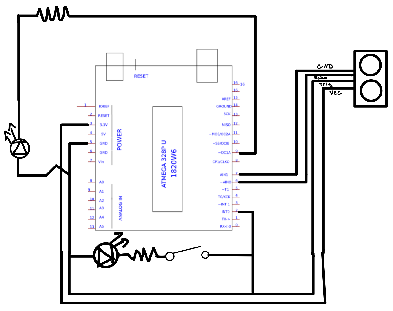
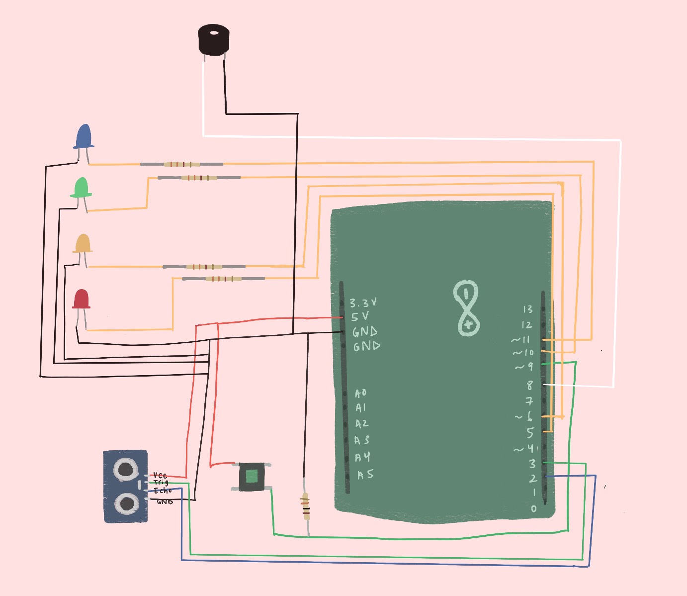
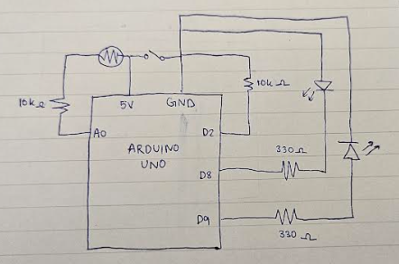
The design, as mentioned above uses a potentiometer to change change the value of the choice number the user will select. A pushbutton switch is used to lock in the answer and get feedback from the LEDs. A blue LED is used as an indicator on how close we are getting to the answer and the red and green ones are used to give feedback if the answer is correct or not. The design also uses one 10k ohm resistor for the button and three 330 ohm resistors for the LEDs.

Her is the schematic of the circuit.
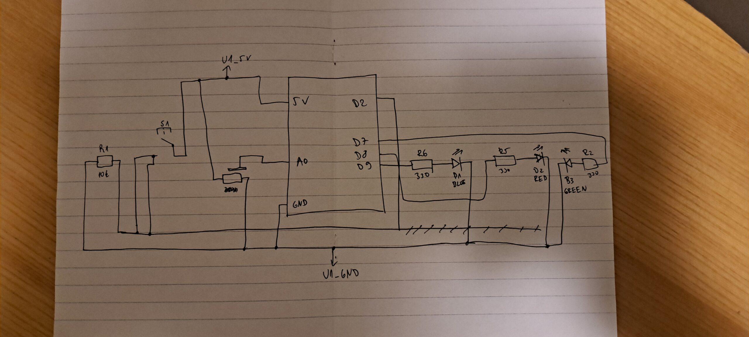
Code I am proud of
int potValue = analogRead(potPin);           // 0–1023
int guess = map(potValue, 0, 1023, 0, 100);  // Convert to 0–100 range

int difference = abs(guess - targetNumber);     // Distance from correct
int brightness = map(difference, 100, 0, 0, 255); // Closer = brighter
brightness = constrain(brightness, 0, 255);
analogWrite(blueLEDPin, brightness);

This part of the code took some time to get right. I used the map function we recently used in class to make the LED brighter the closer we got to the correct number.

Challenges and future improvements

I again faced challenge with the cable management. The breadboard sometimes feels too small for all of the cables, sensors and resistors to fit and a lot of time when I would finish plugging a resistor in I would accidently unplug a cable with my hands. This is something I definitely want to work on for future projects. As for this design specifically, I would like to implement a reset button so the whole device doesn’t need to be reset every time a guess is made, also some audio queues would probably be a nice addition to the whole concept. Maybe also including a screen from which the user could see what numbers they are choosing would bring the game to a whole another level. Overall working with Arduinos is very fun and I enjoy it even more with every project we do.

Week 9 – Reading Response

Physical Computing’s Greatest Hits (and misses):

The first category that popped up was a theremin-esque instrument and that’s exactly how I described my week 9 assignment with sound produced based on distance/motion. It’s interesting how motifs get repeated constantly in physical computing. Core functionalities repeat, but how you make it different and your own spin on the functionality makes physical computing worth pursuing. This blog brought up an important point about interactions that have meaning. Rather than simply mimicing a user’s actions or mapping one to one interactions, thinking about why certain interactions are valuable can fuel a physical computing project even more. For example, I really liked the accessibility examples provided like the one where a someone uses their wheelchair as a painting tool as opposed to their limbs.

Making Interactive Art: Set the Stage, Then Shut Up and Listen

Interactive art is a mix of design and art — your piece should invoke the right emotions without having the tell the users how to feel. Just like how a sign doesn’t need to say push or pull on a door — it should be intuitive (design principles). An interactive piece is a conversation, not a one-sided story where the artist tells the user how to feel or approach the piece. The piece can grow and evolve with feedback or reactions the users provide. By listening to their side of the conversion, you can learn a lot about how people behave with your piece and ways to change it. This brings me back to a previous reading response we had about interactivity as not just a response to users’ actions, but a tool for users to create with. By giving users a sense of agency, they’re able to creative the art with you. We as artists might feel inclined to spell out our intentions for audiences and explain how complex our projects are, but if a project is truly complex and thoughtful, it shouldn’t need explanation.

Assignment 9: Digital and Analogue Detection

This is my Analogue and Digital device sensing machine. It uses an Ultrasonic sensor and Push button to change the brightness of LEDs and to toggle them on/off.

Assignment Brief

  • Get information from at least one analogue sensor and at least one digital sensor
  • Use this information to control at least two LEDs, one in a digital fashion and the other in an analog fashion
  • Include a hand-drawn schematic in your documentation

Conceptualisation

The idea for this project was inspired by the desire to create an interactive system that responds to both user input and environmental conditions. I wanted to design a setup where users could actively engage with the system while also observing dynamic feedback. By using an ultrasonic sensor as the analog input, I aimed to create a setup where distance could influence the brightness of an LED, making it visually engaging. Additionally, I incorporated a pushbutton as the digital input to provide manual control over another LED, allowing for a tactile interaction. This combination of sensors and LEDs was chosen to demonstrate how analog and digital inputs can work together in a creative and functional way.

Process

  1. Component Selection: I gathered an Arduino board, an Ultrasonic Sensor (HC-SR04), LEDs, Resistors, Pushbutton Switch, and Jumper Wires

  2. Circuit Assembly: I connected the ultrasonic sensor to the Arduino, ensuring proper wiring for its VCC, GND, TRIG, and ECHO pins. I connected the pushbutton switch to one of the digital pins on the Arduino with an internal pull-up resistor. I wired two LEDs: one LED was connected to a PWM pin for analog brightness control; the other LED was connected to a digital pin for simple on/off functionality.

  3. Code Development: I wrote Arduino code that: Reads distance data from the ultrasonic sensor; maps the distance data to control the brightness of one LED using PWM; reads input from the pushbutton switch to toggle another LED on or off. The code also included debugging statements for monitoring sensor data via the Serial Monitor.

  4. Calibration: I tested and calibrated the ultrasonic sensor by experimenting with different distance thresholds. This involved adjusting the mapping range for brightness control and ensuring accurate detection of distances within 100 cm. For the pushbutton, I verified its functionality by toggling the digital LED on and off during testing.

Challenges

  1. Sensor Accuracy: The ultrasonic sensor occasionally gave inconsistent readings due to interference or non-flat surfaces. To address this, I ensured proper alignment of objects in front of the sensor during testing

  2. False Triggers: Early versions of the code caused unintended behavior due to incorrect wiring and delays in signal processing. I resolved this by carefully re-checking connections and optimizing delay times in the code

  3. Brightness Mapping: Mapping distance values (0–100 cm) to PWM brightness (0–255) required fine-tuning to achieve smooth transitions in LED brightness.

Potential Improvements

  1. Multiple Sensors: Adding more ultrasonic sensors could allow for multi-directional distance sensing, enabling more complex interactions.

  2. Enhanced Visual Feedback: Using RGB LEDs instead of single-color LEDs could provide more dynamic visual responses based on distance or button presses.

  3. Energy Efficiency: Exploring low-power modes and more efficient components could extend battery life for portable applications.

Schematic Diagram

Source Code

// Pin assignments
const int trigPin = 7;       // Trig pin for ultrasonic sensor
const int echoPin = 6;       // Echo pin for ultrasonic sensor
const int buttonPin = 2;     // Digital pin for pushbutton
const int ledAnalogPin = 9;  // PWM pin for analog-controlled LED
const int ledDigitalPin = 13; // Digital pin for on/off LED

void setup() {
  pinMode(trigPin, OUTPUT);
  pinMode(echoPin, INPUT);
  pinMode(buttonPin, INPUT_PULLUP); // Enable internal pull-up resistor
  pinMode(ledDigitalPin, OUTPUT);
  pinMode(ledAnalogPin, OUTPUT);

  Serial.begin(9600); // For debugging
}

void loop() {
  // Measure distance using ultrasonic sensor
  long duration, distance;
  
  digitalWrite(trigPin, LOW);
  delayMicroseconds(2);
  
  digitalWrite(trigPin, HIGH);
  delayMicroseconds(10);
  
  digitalWrite(trigPin, LOW);
  
  duration = pulseIn(echoPin, HIGH);
  
  // Calculate distance in centimeters
  distance = duration * 0.034 / 2;

  // Map distance (0-100 cm) to PWM range (0-255)
  int brightness = map(distance, 0, 100, 0, 255);

  // Control brightness of analog-controlled LED
  analogWrite(ledAnalogPin, brightness);

  // Read pushbutton state
  int buttonState = digitalRead(buttonPin);

  // Toggle digital-controlled LED based on button press
  if (buttonState == LOW) { // Button pressed
    digitalWrite(ledDigitalPin, HIGH);
  } else {
    digitalWrite(ledDigitalPin, LOW);
  }

  // Debugging output
  Serial.print("Distance: ");
  Serial.print(distance);
  Serial.print(" cm | Brightness: ");
  Serial.println(brightness);

  delay(100); // Small delay for stability
}

Week 9 – Analog and Digital Sensors

Description:

I really wanted to try using the ultrasonic motion sensor for this week’s assignment and control both audio and visuals with it. Being able to have your hand control something without touching it seemed cool to me, kind of like the theremin instrument that allows musicians to wave their hand in the air to produce different notes. My assignment is much simpler, but has a similar idea in that the closer your hand gets to the sensor, the lower the pitch. I also have LEDs hooked up that get dimmer the closer your hand gets and brighter the farther away. For the digital sensor, I have a button controlling my 4 LEDs; the button allows you to toggle between the LEDs individually. Once you’ve gone through all the LEDs and press the button again, all of them turn on. 

Video demonstration:

Schematic:

Difficulties:

I had a hard time with the button because it wasn’t as simple as pressing it to toggle between the LEDs. When you press the button, you’re technically holding it and giving it HIGH voltage for multiple frames. That means within one button press, I’m toggling between who knows how many LEDs. However, I only want one button press to change one thing. I did some scouring online and found this state-changing example that made me realize I can just detect when the button goes from LOW to HIGH (off to on). By keeping track of the last button state and current button state, I can detect when the user clicks the button. That instance determines whether or not to toggle between the LEDs: https://docs.arduino.cc/built-in-examples/digital/StateChangeDetection/

Button state change:

// compare current and previous button states, see if there's change
if (buttonState != lastButtonState) {
   // if HIGH, button went from off to on
   if (buttonState == HIGH) {

Mapping distance to LED brightness:

analogWrite(LEDarr[currentLED], map(dist, 0, 20, 0, 255));
if (dist < 3) {
  analogWrite(LEDarr[currentLED], 0);
}

It was also difficult making the different pitches noticeable since the motion sensing isn’t the most accurate and there’s not a huge range to work with. To counteract this, I chose notes that were very far apart from each other to make the change in sound due to distance more apparent. I also made sure to print out the distances to how far a person would comfortably go away from the sensor and used that as my max.

Looking forward:

In the future, it would be nice if maybe I map a specific LED/color to a specific note or melody so that when I play songs from the speaker, the lights match accordingly. It would also be cool if I can play a song from the motion sensor and choose what notes to play given the distance/motion.

Assignment 9: Analogue and Digital

For this week’s assignment, we were tasked with controlling two LEDs using analogue and digital means. For my project, I decided to utilize the photoresistor to control one of the LEDs.

The idea was to have one LED controlled by a button, while the second LED would change its brightness depending on how much light the photoresistor detected. This works through the photoresistor sitting next to the first LED, so when it turns on, the second LED gets dimmer, and vice versa.

The components I used were:

  • Arduino Uno
  • Breadboard
  • Wires
  • 2 LEDs
  • 2 330 ohms resistors
  • 1 button switch
  • 2 10k ohm resistors
  • 1 photoresistor

Video of the circuit:  https://drive.google.com/file/d/18Y1VjX12o3Z_u9x9rxtTDF2E-SOxcpOG/view?usp=sharing

Schematic:

The code:

const int buttonPin = 2;    // Button input pin
const int led1Pin = 8;      // LED1 (button-controlled)
const int photoPin = A0;    // Analog input for photoresistor
const int led2Pin = 9;      // LED2 (brightness controlled by light)

void setup() {
  pinMode(buttonPin, INPUT);      // Set button pin as input
  pinMode(led1Pin, OUTPUT);       // Set LED1 pin as output
  pinMode(led2Pin, OUTPUT);       // Set LED2 pin as output
  Serial.begin(9600);             // Start Serial Monitor for debugging
}

void loop() {
  int buttonState = digitalRead(buttonPin);   // Check if button is pressed

  // Control LED1 based on button
  if (buttonState == HIGH) {
    digitalWrite(led1Pin, HIGH);  // Turn on LED1 if button is pressed
  } else {
    digitalWrite(led1Pin, LOW);   // Otherwise, turn it off
  }

  // Read the light level from the photoresistor
  int lightLevel = analogRead(photoPin);  // 0 (dark) to 1023 (bright)
  Serial.println(lightLevel);            
  // Convert light level into LED2 brightness (invert it!)
  int brightness = map(lightLevel, 0, 1023, 255, 0);
  brightness = constrain(brightness, 0, 255); // Make sure value stays in range

  analogWrite(led2Pin, brightness); // Set brightness of LED2

  delay(10);  // Small delay
}

The coding was probably the hardest part, as I was struggling with having the photoresistor convert the binary values into a values that would be suitable for the resisitor, and would show a noticeable decrease in brightness in the second LED.

Overall, this was an interesting project, and I was able to better understand some functions within the Arduino IDE program and the way a photoresistor could be utilized.


Week 9 — Reading Response

Reading Tom Igoe’s articles helped me understand physical computing in a more thoughtful way, beyond just wiring things up and making LEDs blink (which to be fair, I do think is a preconceived notion that I have been gradually worn down through consecutive projects and readings in the class). In the first article (“Physical Computing’s Greatest hits and misses”), I appreciated how he explained that physical computing is really about building systems that can sense and respond to the world around them. This also reminded me of the discussion we had a couple of weeks ago on what defines interactivity. It also stood out to me because it made me think differently about my lie detector project — that I wasn’t just turning on lights but also creating a playful, real-world interaction in response to physical stimuli.

The second article (“Making Interactive Art: Set the Stage, Then Shut Up and Listen”) focused more on the nature of interaction, and it really resonated with me. He explains that real interaction happens when the user has control over the timing and nature of the input, rather than just pressing a button and triggering a fixed response. That reminded me of how, at first, my green LED would turn on as long as the button was pressed, even if there wasn’t enough pressure. It didn’t feel right, and reading this made me realize why. The system was reacting too easily, without enough real input from the user (this is also my re-interpretation of the event as well since this connection was mentally made a bit later). Adding a lower threshold fixed that and made the interaction more accurate. I think, overall, I’m left with concepts and ideas that can serve as tools to frame my projects and skills in this class, especially in the aspect of understanding interactivity and intentionality.

Week 9 – Serial/Analog Input – Smile and Wink!

CONCEPT:

For this week’s assignment, I made a smiley face with two glowing eyes, where they “wink” in between. One of the LEDs brightness was controlled using a photoresistor, and the other turned on/off using a switch.

MATERIALS USED:

Arduino UNO

Breadboard

Photoresistor

10K Ohm resistor

330 Ohm resistor

Switch

LED

Jumper wires

WORKING:

So one of the LEDs are controlled using the photoresistor. It gets brighter when the photoresistor is covered(less light), and vice versa. The other LED is controlled using the switch. The code for it is as follows:

const int button = 2;
const int led1 = 13;
const int led2 = 9;
const int ldr = A0;

int state = LOW; //state of LED1
int brightness = 0; //brightness of LED2
int ldrValue = 0; //photoresistor value

void setup() {
  pinMode(button, INPUT_PULLUP); 
  pinMode(led1, OUTPUT);
  pinMode(led2, OUTPUT);
  
  //serial monitor for debugging
  Serial.begin(9600);
}

void loop() {
  if (digitalRead(button) == LOW) {
    state = HIGH;  //turn LED1 on
  } else {
    state = LOW;   //turn LED1 off
  }
  
  //read photoresistor value and map it to LED2 brightness (0 to 120)
  ldrValue = analogRead(ldr);
  brightness = map(ldrValue, 0, 1023, 0, 120);
  
  Serial.print("LDR Value: ");
  Serial.println(ldrValue);
  
  //control LED1 using switch (physical input)
  digitalWrite(led1, state);
  
  //control LED2 brightness using analog input
  analogWrite(led2, brightness);

  delay(100);  //small delay for stability
}

CHALLENGES :

The challenging part about this was my biggest careless mistake! I put the LED on oppositely (anode and cathode), so I spent a good 30 minutes trying to figure out what went wrong. I also used the serial monitor to help with debugging.

Hand drawn schematic:

LINK TO VIDEO :

https://youtube.com/shorts/UVZ-qTWX1aE?feature=share

IMPROVEMENTS :

I would like the photoresistor-controlled LED to be better, maybe some other form of coding that makes it more…interesting. I also realised that we wink using our eyelids and not the eyes themselves, but overall, as a form of cartoonish smiley-ness, I’m happy with this project. It was a fresh start after the spring break!

Physical Computing’s Greatest Hits (and misses)

The text explores recurring themes in physical computing projects and makes a strong case for embracing these ideas, even if they’ve been done before. I really appreciated the encouragement to view these themes as starting points for originality rather than dismissing them as unoriginal. It’s easy to feel discouraged when you think your idea isn’t new, but this perspective reframes those recurring concepts as opportunities to innovate and personalize. For example, the section on theremin-like instruments stood out to me. While the basic idea of waving your hand over a sensor to create music might seem simple, the challenge lies in adding meaningful gestures or context to make it more expressive and unique. That idea of taking something familiar and pushing it further really resonates with me.

One theme that caught my attention was the “gloves” section, particularly the drum glove. I love how it builds on a natural human behaviour- tapping rhythms with your fingers- and turns it into something interactive and fun. The text points out that gloves already come with a gestural language we understand, which makes them accessible while still offering room for creativity. I started imagining how I could expand on this concept, maybe by incorporating haptic feedback or connecting the gloves to other devices for collaborative performances. It’s exciting to think about how these simple ideas can evolve into something much bigger.

That said, not all the themes felt equally engaging to me. For instance, while “video mirrors” are visually appealing, the text acknowledges that they lack structured interaction and often devolve into simple hand-waving. I agree with this critique- while they’re beautiful, they don’t feel as immersive or meaningful compared to something like “body-as-cursor” projects, which involve more dynamic movement and interaction. It made me think about how important it is to balance aesthetics with functionality in interactive design.

Overall, this text inspired me to see recurring project ideas not as limitations but as creative challenges. It also got me thinking about how physical computing bridges the gap between art and technology in such playful and human ways. Moving forward, I want to approach my own projects with this mindset- taking familiar concepts and finding ways to make them personal, meaningful, and interactive. There’s so much potential in these themes, and I’m excited to explore where they could lead.

Making Interactive Art: Set the Stage, Then Shut Up and Listen

This text really made me rethink the way I approach art and creativity. I love how it frames interactive art as a conversation between the artist and the audience, rather than a one-sided statement. The idea that the audience completes the work through their actions is so refreshing- it feels collaborative and alive. It reminds me of immersive installations like Yayoi Kusama’s “Infinity Rooms,” where the experience is deeply personal and shaped by how each person interacts with the space. I’m drawn to this idea of stepping back as an artist and letting others bring their own perspectives to the work.

At the same time, I struggle with the idea of completely “getting out of their way.” While I understand the importance of leaving room for interpretation, I think too little guidance can leave people feeling lost or disconnected. The text mentions giving hints or context, but it doesn’t really explain how much is enough. For example, if an interactive piece doesn’t make it clear what’s meant to be touched or explored, people might misinterpret it or feel unsure about how to engage. I think there needs to be a balance- enough structure to guide people without taking away their freedom to explore.

This text really got me reflecting on my own creative process. It made me think about how interactive art mirrors other forms of storytelling, like theater or video games, where the audience or players shape the experience. I love the idea of creating something that invites others to bring their own interpretations, but I also want to make sure they feel welcomed into that process. It’s definitely something I’ll keep in mind as I work on my own projects- how to create that balance between structure and freedom so that my work feels open but still accessible.

Week 9: Analog input & output

Concept:

This project is a reaction timer game built using an Arduino, a push button, a potentiometer, and two LEDs. The main idea is to test how fast a person can react after seeing a visual signal. One LED acts as the “start signal” light — when it turns on, the player must press the button as quickly as possible. The potentiometer controls how difficult the game is by adjusting the random delay time before the signal LED lights up. After the player presses the button, the Arduino measures their reaction time and shows it on the computer screen through the Serial Monitor.

The second LED is used to make the project more interactive by representing the player’s reaction speed through brightness. If the player reacts quickly, the second LED lights up brightly. If the reaction is slower, the second LED is dimmer. This gives instant visual feedback without needing to check the Serial Monitor every time. The whole project is a fun way to learn about digital inputs, analog inputs, and timing functions with Arduino, and it can easily be expanded with sounds, scores, or even multiple players later on.

int pushButton = 2;  // Button pin
int potPin = A0;     // Potentiometer pin
int ledPin = 8;      // LED pin

void setup() {
  Serial.begin(9600);
  pinMode(pushButton, INPUT_PULLUP);
  pinMode(ledPin, OUTPUT);
}

void loop() {
  int difficulty = analogRead(potPin);  // Read difficulty setting
  int waitTime = map(difficulty, 0, 1023, 1000, 5000); // Map to 1-5 seconds
  
  Serial.println("Get Ready...");
  delay(random(waitTime));  // Wait random time based on potentiometer
  
  digitalWrite(ledPin, HIGH);  // Turn LED ON (reaction signal)

  unsigned long startTime = millis();  // Start counting time
  while (digitalRead(pushButton) == HIGH) {
    // Wait for button press
  }
  unsigned long reactionTime = millis() - startTime;  // Reaction time calculation
  
  digitalWrite(ledPin, LOW);  // Turn LED OFF after button pressed
  
  Serial.print("Reaction Time (ms): ");
  Serial.println(reactionTime);
  
  delay(3000);  // Wait 3 seconds before starting again
}

Challenges:

My Arduino Board got stuck in an infinite loop through a test code I ran previously and stopped accepting any further code uploads. Due to this, I had to change my project idea and use a friend’s Arduino to run the code.

New Concept:

This is a simple circuit using 2 LEDs, a potentiometer, and a switch button. The potentiometer controls the brightness of the LED while the other LED is controlled by the button.