All Posts

Week 12 – Finalised Concept

Final Project Proposal: ExpressNotes

For my final project, I am creating ExpressNotes, an interactive audiovisual system that combines sound, visuals, and physical input to inspire real-time artistic expression. The system uses an Arduino connected to seven push buttons and a potentiometer. Each button represents a musical note in the A-G scale. When the user presses a button, the Arduino detects the interaction and sends the corresponding note information to a P5.js sketch running on a computer. The potentiometer allows the user to control the volume of the sounds being played. In response to these inputs, P5.js generates synchronized piano sounds and matching visual effects, forming a dynamic and engaging artistic experience that evolves with each interaction.

ExpressNotes is designed to turn the user into both a musician and visual artist. Each button press is more than a sound—it becomes a trigger for a burst of visual energy. The system fosters expressive exploration by offering real-time feedback. For example, pressing the “C” button might create a ripple of soft blue circles along with a gentle piano tone, while pressing “F” could unleash rotating magenta shapes accompanied by a brighter sound. Over time, the visual canvas builds up in complexity and motion, reflecting the rhythm and emotion of the user’s choices.

The Arduino is programmed to listen for button presses and read the current position of the potentiometer. When a button is pressed, it sends a message like “note:C” to the P5.js program. It also continuously reads the potentiometer value, which ranges from 0 to 1023, and sends volume updates in the form of messages like “volume:750.” The Arduino serves solely as a sender—it does not receive any data back from P5.js.

On the software side, P5.js is responsible for listening to the serial port and interpreting the messages from the Arduino. When it receives a note message, it plays the corresponding piano note and triggers a unique visual effect associated with that note. When it receives a volume message, it maps the value to a usable range and updates the volume of the audio accordingly. Each note is associated with a different visual response to create a richer and more immersive experience. For instance, the “A” note may create blue ripples, “B” may release golden triangle bursts, “C” may trigger expanding red squares, “D” might produce spiraling cyan patterns, “E” could generate flowing green waves, “F” may show rotating magenta shapes, and “G” could spark star-like white particles.

When the user interacts with the buttons and the volume knob, they create a personal audiovisual composition. The experience is fluid, immediate, and emotionally engaging. Each session is unique, and the visual display reflects the rhythm, timing, and feeling of the musical input. The evolving artwork becomes a living canvas of user expression.

In nutshell, ExpressNotes demonstrates the creative potential of combining physical sensors with generative audio-visual programming. It allows users to explore sound and visual art intuitively, transforming simple button presses into an expressive performance. The project encourages artistic freedom, emotional engagement, and a playful connection between sound and image, making it a compelling example of interactive media design.

Week 12: Final Project Proposal

Smart House System

For this project, I am designing a Smart House System using Arduino UNO and p5.js.
The idea was to automate key parts of a house and parking lot, and to create a more interactive experience using voice announcements made with p5.js.

The main features include:

  • Automatic main door that opens when a person approaches.

  • Car parking system that displays the number of available spots and automatically opens a parking barricade if spots are available.

  • Indoor lighting system that switches on when it gets dark, based on a photoresistor sensor.

  • Real-time voice announcements generated in p5.js based on Arduino sensor inputs, to make the system feel alive and responsive during an exhibition demo.

Design and Description of Arduino Program

The Arduino is responsible for all hardware sensor readings, actuator controls, and sending/receiving messages to and from p5.js.

Component Type Description
Distance Sensor (Main Door) Input Measures distance to detect a visitor near the main door.
Distance Sensor (Parking Entrance) Input Detects a car approaching the parking gate (entry).
Distance Sensor (Parking Exit) Input Detects a car leaving the parking area (exit).
Photoresistor (Indoor Lighting) Input Detects ambient light levels to determine if indoor lights should be turned on.
Servo Motor (Main Door) Output Opens or closes the main entrance door based on visitor detection.
Servo Motor (Parking Gate) Output Opens or closes the parking barricade when a car is allowed entry.
LED Display Output Shows the number of parking spots left.
Indoor LEDs / Lights Output Turns indoor lights on/off based on photoresistor readings.

Design and Description of p5.js Program

The p5.js program is responsible for interaction, feedback, and visualization.

Main Tasks:

  • Connects to Arduino through Serial communication.

  • Reads messages sent from Arduino (e.g., “door_open”, “lights_on”, “parking_spots:3”).

  • Plays real-time voice announcements using the p5.speech library based on events detected.

  • Displays a virtual dashboard showing the current number of available parking spots and statuses like door open/closed, lights on/off.

Voice Announcements Based on Arduino Events:

Arduino Message p5.js Voice Announcement
door_open “Welcome! The door is opening.”
car_entry “Vehicle detected. Checking parking availability.”
car_exit “Vehicle exited. Parking spot now available.”
parking_full “Parking is full. Please wait.”
lights_on “Lights are now on for your comfort.”
lights_off “Lights are off to save energy.”

Week 12 – Final Concept – Go Ichi-Go!

Concept and Overview:

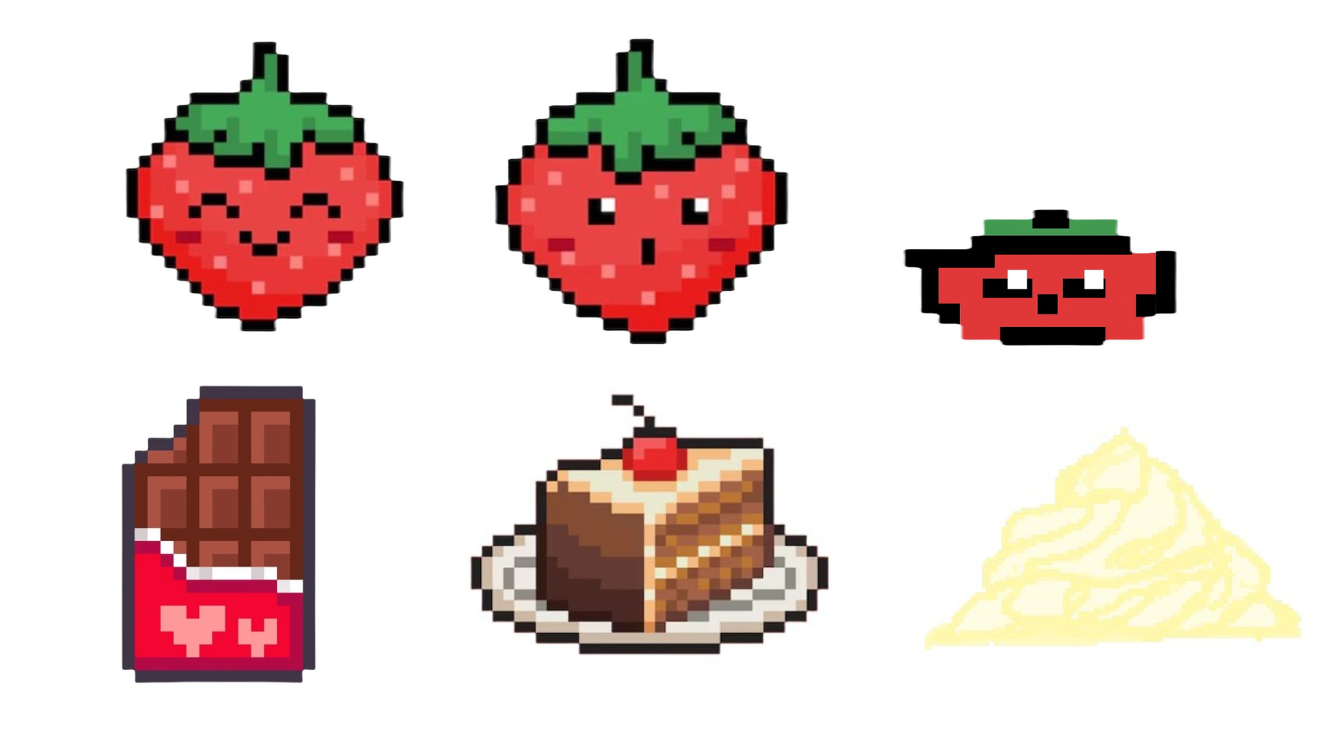
For my final project, I want to create a game called “Go Ichi-Go!”. So the game would have a character called Ichigo (strawberry), who runs and has to jump over obstacles like jumping puddles of whipped cream, and towers of chocolate, and slide under floating slices of cake. After each jump/dive, there would be randomised text giving cute strawberry themed puns. For this I’ll use an array of randomised puns. 

There would also be sound effects for each jump or dive. There would be two buttons to jump or dive, using Arduino, and a button to start/restart the game. The player wins after successfully overcoming 10 obstacles.

If they win, it would display a congratulations image and a restart option. This triggers the movement of the servo motor, which will dispense candy as the reward for winning.

If they fail to do so, then it would just go to a Game Over state with a restart button. 

Things I’ll need :

  1. Arduino Uno
  2. Breadboard
  3. Servo Motor
  4. Three arcade buttons
  5. Jumper wires
  6. Alligator clips/wires
  7. Laser print arcade box
  8. Candy box dispenser

The serial communication would be like this:

From Arduino to p5: 

Pressing the “Start” button sends an “S” to p5, to start/restart the game.

Pressing the “Jump” button sends a “J” to p5, triggering the character to jump.

Pressing the “Dive” button sends a “D” to p5, triggering the character to jump.

if (digitalRead(startBtn) == LOW) {
   Serial.println("S");
   delay(100);
 }
 if (digitalRead(jumpBtn) == LOW) {
   Serial.println("J");
   delay(100);
 }
 if (digitalRead(diveBtn) == LOW) {
   Serial.println("D");
   delay(100);
 }

From p5 to Arduino:

At the end, when they win, P5 sends a “C” to Arduino, triggering the movement of the servo motor. 

serial.write('C\n');

Schematic:

DESIGN :

I want to make this game in a very kawaii retro vibe, but also focus more on the interaction design on the game itself, something I learnt from my midterm. So this time, I used Canva to layer up the illustrations, instead of drawing them from scratch. 

I also want to laser cut a box to hold all this together and make it look like one of those retro arcade game boxes. 

So far, I’ve just started the basic outline of the code, so I haven’t gotten very far with it. 

Next steps

  1. Finish game interface and troubleshoot 
  2. Laser cut arcade box pieces
  3. Make a box structure for the candy dispenser


Week 12 – Final Project Proposal

My final project is a bomb defusal game inspired by Keep Talking and Nobody Explodes. Just like in the original game, the player has to disarm several modules on the bomb in order to successfully defuse it. Currently I plan to include four types of modules. The first is Simon Says, using four buttons and corresponding LEDs. The second is a single larger button connected to a multicolored LED, which will be disarmed differently depending on the color. The third is an adaptation of cutting wires, where the player will have to either disconnect or rearrange the wires correctly. The last module requires the user to use a potentiometer as a tuning knob and try to hone in on the correct frequency.

The Arduino will be responsible for reading the inputs from each module, and correctly lighting the LEDs where needed. I also intend to use the display screen from our kits to show the bomb’s timer if possible, and use a buzzer/speaker to create a beeping noise. The p5.js side will be responsible for initializing a new game and managing its state. It will receive the inputs from Arduino and verify them, and send back the confirmation if a module was completed. I also want to use it to render a representation of the bomb, including the correct LED lights and countdown timer. In line with the original game, it can also work to provide the information needed to disarm the more complicated modules. In terms of interaction, p5.js will be used to start the game and will display a win/loss screen after it ends.

I have started writing some basic code for both components:

/*
Final Project (WIP)
By Matthias Kebede
*/


// // // Global Variables
// // Inputs
const int tempIn = A1;

// // Outputs
const int tempOut = 8;
const int speakerPin = 10;

// // Communication and State Information
int sendInterval = 100;   # ms
int lastSendTime = 0;   # ms
int timer = [5, 0];   # minutes, seconds
int beepFreq = 1000;   # hz
int beepDur = 50;   # ms
int beepInterval = 100;   # ms
int lastBeepTime = 0;


// // // Main Processes
void setup() {
  Serial.begin(9600);

  // // Inputs and Outputs
  pinMode(tempIn, INPUT);
  pinMode(LED_BUILTIN, OUTPUT);
  pinMode(tempOut, OUTPUT);

  // // Check built-in LED
  digitalWrite(LED_BUILTIN, HIGH);
  delay(200);
  digitalWrite(LED_BUILTIN, LOW);

  // // Start handshake w/ p5.js
  while (Serial.available() <= 0) {
    digitalWrite(LED_BUILTIN, HIGH);
    Serial.println("123"); // identifiable starting number
    delay(300);
    digitalWrite(LED_BUILTIN, LOW);
    delay(50);
  }
}

void loop() {
  // // Wait for p5.js
  while (Serial.available()) {
    digitalWrite(LED_BUILTIN, HIGH);

    int firstVal = Serial.parseInt();
    if (Serial.read() == '\n') {
      analogWrite(tempOut, firstVal);
    }

    if (lastSendTime > sendInterval) {
      lastSendTime = 0;
      int sendVal = analogRead(tempIn);
      int mappedVal = map(sendVal, low, high, 0, 255);
      Serial.println(sendVal);
      delay(1); // stabilize ADC? check this
    } 
    else {
      lastSendTime++;
    }

    digitalWrite(LED_BUILTIN, LOW);
  }
}


// // // Helper Functions
void timerSound() {
  if (lastBeepTime > beepInterval) {
    // // Less than 30 seconds remaining
    if (timer[0] == 0 && timer[1] < 30) {
      tone(speakerPin, beepFreq + 500, beepDur);
    }
    // // Final minute but more than 30 seconds
    else if (timer[0] == 0) {
      tone(speakerPin, beepFreq + 250, beepDur + 25);
    }
    else {
      tone(speakerPin, beepFreq, beepDur + 50);
    }
  }
  else {
    lastBeepTime++;
  }
}
/*
Final Project
By Matthias Kebede
*/


// // // Global Variables
let debug = true;
let gameState = 'menu'; // menu, playing, win, lose
let game;
// // For display
let play, menuTitle;


// // // Main Processes
function preload() {
  
}

function setup() {
  createCanvas(600, 450);
  createMenu();
}

function draw() {
  background(220);
  
  switch (gameState) {
    case 'menu':
      showMenu();
      break;
    case 'playing':
      game.display();
      break;
    default:
      break;
      
  }
}


// // // Classes
class Game {
  constructor() {
    this.gameover = false;
    this.start = millis();
    this.time = 30;
    this.modules = [];
  }
  display() {
    text(`Time: ${Math.floor(this.time)}`, width/2, height/2);
    if (!this.gameover) {
      this.update();
    }
    else {
      text("Gameover", width/2, height*0.2);
    }
  }
  update() {
    for (let module in modules) {
      module.checkStatus();
    }
    // // Update timer
    if (this.time > 0 + 1/frameRate()) {
      this.time -= 1/frameRate();
    }
    else {
      this.time = 0;
      this.gameover = true;
    }
  }
}

class Module {
  constructor() {}
  checkStatus() {}
}


// // // Interaction
function mouseClicked() {}


// // // Displays
function createMenu() {
  // // Menu Title
  menuTitle = createElement('h1', "Main Menu");
  menuTitle.size(9*18, 100);
  menuTitle.position((width-menuTitle.width)/2, height*0.2);
  // // Play Button
  play = createButton("Play");
  play.size(width/5, height/15);
  play.position((width-play.width)/2, height/2);
  play.mousePressed(function() {
    game = new Game();
    gameState = 'playing';
    removeElements();
  });
}
function showMenu() {}


// // // Helper Functions


Week 12 – Finalised Concept

For my final project, I am building a 3D Music Interface that allows users to trigger both 3D visual animations and musical sounds through a physical touch-sensitive controller. The interface will be made out of cardboard and tinfoil touchpads connected to an Arduino. Each physical touch will trigger a corresponding 3D box animation in p5.js, along with a musical note generated directly in the browser using the p5.sound library. The goal is to create a playful, intuitive instrument that connects physical gestures to both sound and visual expression immediately and reliably.

Arduino Program Design

The Arduino will act as the input device, reading signals from multiple touch-sensitive pads made of tinfoil and cardboard.

  • Inputs:

    • Each touchpad will be connected to a digital input pin.

    • When the user touches a pad, it will register a HIGH signal on that pin.

  • Processing:

    • The Arduino continuously checks the state of each touchpad inside the loop() function.

    • When a touch is detected, the Arduino sends a unique identifier through Serial communication.

    • Each touchpad is mapped to a different number (e.g., 0, 1, 2, 3, up to 7).

  • Outputs:

    • The Arduino only sends data to p5.js. It does not control any external outputs like LEDs or motors.

  • Communication with p5.js:

    • Sends a single-digit number (0–7) each time a pad is touched.

    • No information is received from p5.js back to Arduino because the communication is one-way (Arduino → p5).

Example behavior:

  • Touchpad 0 is touched → Arduino sends 0 over Serial.

  • Touchpad 1 is touched → Arduino sends 1 over Serial.

    …and so on for each pad.

    The Arduino sketch will look something like this (early draft structure):

    void setup() {
      Serial.begin(9600);
      pinMode(touchPin1, INPUT);
      pinMode(touchPin2, INPUT);
      ...
    }
    
    void loop() {
      if (digitalRead(touchPin1) == HIGH) {
        Serial.println(0);
      }
      if (digitalRead(touchPin2) == HIGH) {
        Serial.println(1);
      }
      ...
    }
    

p5.js Program Design

The p5.js program will be responsible for receiving data from Arduino and producing both sound and visual feedback based on the input.

  • Receiving data:

    • p5.js listens to the Serial port using the serialEvent() function.

    • Each time it receives a number from Arduino (0–7), it triggers two actions:

      1. Visual: Activates a specific 3D box animation (e.g., spin, color change, movement).

      2. Audio: Plays a specific musical note using the p5.sound library.

  • Processing:

    • The incoming serial value is matched to the corresponding element in an array of 3D boxes.

    • A corresponding musical note (e.g., C2, D2, E2, F2…) is also mapped and played.

  • Outputs:

    • On the screen: Real-time 3D animations using WEBGL (such as spinning boxes).

    • In the browser: Sound output through the computer speakers using p5.sound.

  • Communication with Arduino:

    • p5.js only receives data from Arduino.

    • No messages are sent back

Example behavior:

  • Receive 0 → Box 0 spins and note C2 plays

  • Receive 1 → Box 1 spins and note D2 plays

  • Receive 2 → Box 2 spins and note E2 plays

    Early pseudocode for handling serial data:

function serialEvent() {
  let inData = Number(serial.read());
  if (inData >= 0 && inData < boxes.length) {
    boxes[inData].play(); // Spin box
    playNote(inData); // Play corresponding sound
  }
}

Next Steps

  1. Build a basic cardboard and tinfoil prototype for the touch-sensitive interface

  2. Test Arduino with simple touch sensor code, confirming that touchpads reliably trigger digital input signals

  3. Set up p5.serialport and confirm that Arduino can send and p5.js can receive serial data properly
  4. Prepare an initial sound mapping using the p5.sound library

  5. Create a rough version of the 3D visualizations (boxes spinning in response to input)

Week 11 – Final Project Idea

For my final project, I am creating a 3D physical music interface that uses Arduino and p5.js to produce both sound and visual feedback in real time. The interface will be built from cardboard and tinfoil touchpads connected to an Arduino. Each physical input will trigger 3D animations on screen and simultaneously play musical notes or sound effects through p5.js’s sound library.

The goal is to design an experience where physical gestures directly generate both visual creativity and musical expression, offering a playful and intuitive interaction. Touching different areas results in unique audiovisual combinations, allowing users to “perform” across both sound and visual mediums.

Inspired by projects like Browser Synth, Interactive Soundboard with p5.js, and Visual Music Keyboards (examples attached), my final project will explore how homemade interfaces can connect physical creativity to browser-based multimedia environments.

Implementation:

  • Arduino: Detecting touch interactions

  • p5.js:

    • Processing serial input from Arduino

    • Triggering real-time 3D graphics (WEBGL)

    • Playing sound using the p5.sound library

Vision:

For this project, my vision is to create an intuitive and playful instrument that connects physical touch to both sound and visual expression. I want the final product to feel immediate and responsive so that when a user touches different parts of the physical interface (buttons/controllers), they should instantly hear a corresponding musical note and see a visual reaction on the screen. My goal is to ensure that the interaction feels clear and easy to discover, even for someone using it for the first time, while also offering enough variety for users to improvise and experiment with the music instrument. Consistency and reliability are also important: every touch should reliably trigger a specific, predictable response without delay.

Introducing p5.js - Building a Generative AI Music Visualizer with  JavaScript and React Codédex | Build an Interactive Soundboard with p5.js
Build a Web Audio Synthesizer in the Browser with p5js

Finalized Concept-week12

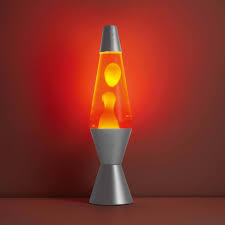
For my final project, I’m creating an interactive Mood Tree Visualizer—a small Christmas tree decorated with RGB LEDs that change colors based on sound  input. The physical tree will be paired with lava lamp-inspired digital visuals in P5.js, creating a cohesive, immersive experience that blends the physical with the virtual. The LEDs on the tree and the blobs on the screen will respond dynamically to sound levels (like clapping, talking, or music) and mood selections .

This playful project is about visualizing emotions in a cozy, festive, and engaging way, letting users express energy levels through both the physical glow of the tree and the flowing digital visuals.

inspiration:

Arduino : Inputs & Outputs:

sound sensor:Captures ambient sound intensity. Louder sounds trigger more active LED patterns and more dynamic P5.js animations.

  • Calm: Blues/Purples

  • Medium: Greens

  • Excited: Reds/Orange

    P5.js Program Design: Inputs & Outputs

    • Inputs from Arduino:

      • Sound Levels:
        Modulate the size, speed, and behavior of the lava blobs.

      • Mood Selection:
        Switch between color palettes and animation styles that match the LED colors.

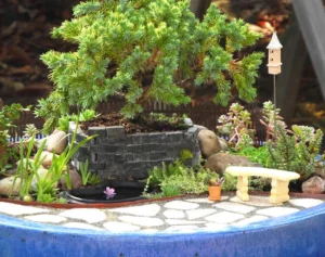
or instead I will create My final project is a Mood House Visualizer a small interactive installation where a miniature house lights up in response to sound. Using an Arduino with a microphone sensor, I will control five RGB LEDs embedded because Arduino doesn’t have enough current for more than 5 led lights or I might just add the led lights for each colors and I will make a mini garden it will act the same way the tree should act the difference is going to be in the appearance of the project

Week 11- Serial Communication

1. Concept

There are 3 parts to the project:

(1) Light Dependent Resistor (LDR) readings are sent from Arduino to p5js. The ellipse in p5js moves on the horizontal axis in the middle of the screen depending on the LDR readings. Nothing on arduino is controlled by p5js.
(2) Control the LED brightness from p5js using mouseX position. The more right the mouse position, the higher the LED brightness.
(3) Taking the gravity wind example (https://editor.p5js.org/aaronsherwood/sketches/I7iQrNCul), every time the ball bounces one led lights up and then turns off, and you can control the wind from the potentiometer (analog sensor).

2. Highlights: Challenges and Overcoming Them

(1) The circle position was not changing in response to the brightness of the surroundings. We attempted to tackle this problem by checking the serial monitor as to whether LDR readings are being read. After confirming the LDR’s functionality, we closed the serial monitor proceeded to use p5js and use the right serial port. However, the circle position was still not changing. With help from Professor, we streamlined our code to include just about all that seemed necessary. This worked!


(2) The LED was flickering. We did not know why. Alisa thought that the delay(50) must be at after instead of before analogWrite(ledPin, brightness). However, that did not solve the problem. Samuel thought to remove the delay(50). It still did not work. We decided to try to map the mouseX position (ranging from 0 to 600) to the range of 0 to 255 in Arduino instead of p5js. This worked!


(3) To code the 3rd assignment. I worked alongside many different individuals, Alisa, Samuel, Haris, (even Prof Aya’s slides). I was having trouble at every stage of the hardware aspect, from safari stopping the code from interacting with the Arduino, to then having serial issues with the laptop. I was able to piece together work until I finally had it working in the end. The coding aspect was simple overall, as the base code only had to be minority amended to take inputs from the Arduino, and the LED had to complete an action based on the running programme.

3. Video

Part 1:

Part 2:

Part 3:

4. Reflection and Future Areas of Improvement

Our challenges emphasized the need for understanding the code that allows communication between p5js and Arduino. Without understanding the code, it is difficult to make the right removals or changes necessary to achieve the results we are hoping to.

It would be great to find out why the LED did not flicker when the mapping was performed in Arduino rather than p5js. Is this related to PWM?

Week 12 – Final Project Proposal : Canon Powered Cornhole Game

Introduction:

Growing up in a South Asian country, I consumed American Media – films,  documentaries, comedy skits, and even FOX News for my daily dose of reliable news. It was during this time that I happened to have been introduced to the carnival game of ‘Cornhole’  during a KSN-TV’s broadcast on Kansas country-side fair. A mix of basketball and golf with a southern dialect to it – I found it to be fascinating. It was so fascinating that when I was overwhelmed by so many ideas to choose from for this final project, I decided to go with a ‘Canon Powered’ Cornhole Game. Instead of tossing by hand, participants decide orientation in X and Y axis, and let the canon shoot out the corn bag. In our case, it would be a small sack filled with weight.


Amazon.com : Super Fun, Portable Mini Desktop Cornhole Set of 2. Coated Wood Boards with 4 Red 4 Blue Bags. Gift for Students, Office Employees or Work from Home. Simple Easy Tabletop

Canon:

The canon would be a 3d printed model. Not big, just about big as my Week 9’s canon. Yes, this is a continuation of that project! That was a candy canon that moved in X axis. This is a fully functional canon with loading and reloading capabilities!

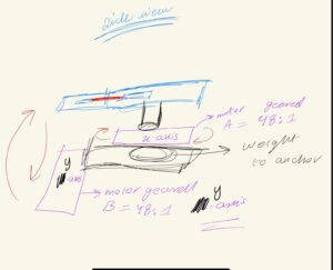
The sketches below visualizes the working and highlights the basic design of the canon. The first one shows how to concept is imagined to be. The canon releases the inside barrel powered by an elastic material having stored the elastic potential energy. That potential energy is released and converted into kinetic energy. This kinetic energy and speed coupled with momentum results in impulse provided to the sack which turns its inertia to a trajectory.

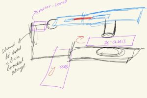
The side view demonstrates the use of two motors, one oriented for x-axis movement and the other one for y-axis movement.

The supported stand on the left end with a claw-like  grappler helps keep the canon loaded. Upon trigger, it will release and let the tension of the elastic loose which will lead to forward release mechanism.

Arduino and P5 Program :

The movement of this canon will be controlled by gyroscope mounted on to gym-gloves. The gloves will also have the flex sensors, so that with hand tilt and movement, corresponding movement along x and y-axis will take place. When the hands are clenched , it will result to the release mechanism being triggered. A pressure sensor will be put underneath the hole/target to detect if the ball/sack has landed. The p5 program will first start off with a menu with  screen offering the user to play or go over instructions. This game will be both in virtual and real domain. The game will start with a 1 minute counter. For each corn in the hole, user will get response on the screen with animation and led will light up, while also points would increase.  When in reload state, the user won’t be able to move the robot, this is for convenience as to prevent user from mistakenly moving the robot while reloading. Once the game ends, the robot stops moving and the highscore displayed.

The arduino will control the movement of the three motors as an output signal (PWM), with last one being a servo, it will take input from the gyroscope and flex sensor for the controls. The Pressure sensor under the cornhole will trigger point system and this will be conveyed to the P5  program by and  after having read by the Arduino. The state of servo motor will be conveyed to the p5 program as well. In return, the p5 will communicate back the permission or the kill-switch condition to start or stop the program. It will process and display the state (i.e launch or reload), and will show the points alongside the timmer. I will add in safety nets too to prevent the machine from turning too much and breaking the structure/casing. Last but not the least, it will shutdown the connection between the gloves and the motors once the game has concluded.

Week 11 – Reading Response

Week 11 – Reading Response

Design Meets Disability:

The reading discusses how simple, thoughtful design can be both functional and beautiful, even for products aimed at disability or accessibility. The Eames splint, which was originally designed for injured soldiers, is appreciated for its aesthetic and innovative qualities. It challenges the idea that medical products should prioritize function over form. Additionally, it critiques how overly complex designs  intended to be universally accessible, often end up being cognitively inaccessible, highlighting the importance of simplicity.

The text differentiates the idea of “universal design” with the idea of “good design,” claiming that accessibility usually comes from simplicity rather than complexity. It references greate designers like the Eameses and Naoto Fukasawa for creating objects where form and function are seamlessly integrated without overcomplicating the user experience. Overall, the author highlights that designing for disability should not lower design standards but rather inspire innovation and beauty. After reading the text, I began rethinking how design for disability is often approached today.