Things to work on:
- trigger with lever mechanism
- bearings – lazy-susan incase of emergency only
- release mechanism – servo
- narrow pipe and pingpong stopping mechanism

Things to work on:
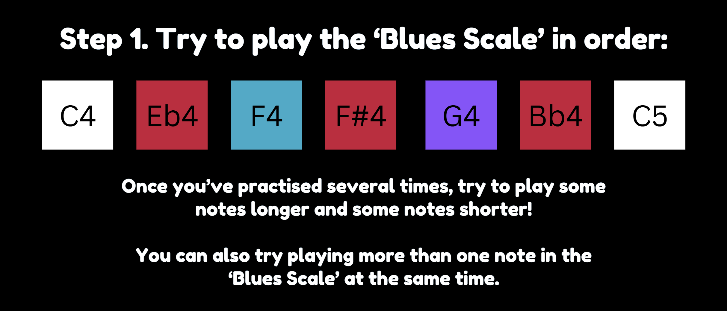
My final project helps users, especially beginners, to learn how to play the piano and learn how to jam to the blues music style. I created a mini-piano consisting of 2 octaves plus one key (spanning notes C4 to C6), which is a welcoming size for beginners. A visualization of a piano is displayed on the p5js sketch, which can be helpful for the piano player to see an animated pressed key and listen to the relevant audio for that pressed key.
The piano is color-coded by note, so that note “C” is white, “D” is orange, “E” is red, “F” is blue and so on. This was a deliberate choice because seeing different colours on the piano can help users familiarize themselves with the positions of the keys over time. Additionally, I used this presentation slide deck with instructions to play the notes, color-coded, in order (example in Fig. 1). Thus, as users see the color-coded notes on the presentation and try to follow it, they could more quickly and easily match it to the note on the physical piano that they should play.
In the communication from Arduino to p5, a string is sent line-by-line containing note name, followed by “=”, followed by note state (either 0 or 1 depending on if it’s considered pressed or not). activeSerialNoteStates is an important variable that stores the latest state (0 or 1) received from Arduino for each note name. Based on the current state of a particular key in activeSerialNoteStates, the handlePressEvent() and display() for that key is called.
Tomorrow and this Sunday, I could try to work on building the circuit.
References:
Finalized concept for the project:
My final project concept is inspired by a popular game called Piano Tiles. My idea is to create a sturdy, fully functional four-key piano connected to an Arduino. Users will be able to physically play the game using this piano, while the gameplay will be displayed on a laptop screen and recreated in p5js, with some differences like a life powerup.
Design and description of what your Arduino program will do with each input and output and what it will send to and/or receive from P5
My arduino program will be in charge of sending all the inputs from the push buttons when a player presses a key on the piano to the p5js. This will be similar to the musical instrument assignment we did in class except the speaker will not be in the arduino but rather an output on the computer from p5 to see if the player pressed the right key in the right time frame.
Design and description of what P5 program will do and what it will send to and/or receive from Arduino:
Speaking of which, my p5js program will run the graphics for the game itself with users seeing the tiles they have to click. It will receive the input from the Arduino of when the user has clicked the piano key and use logic to make sure that was correct according to the game rules. If not, the game will end unless the player has an extra life which can be received in the game by pressing all 4 tiles 3 times at a certain point in the song.
I’m currently working on the 3d design for the piano. Right now I found a file online that looks like this:
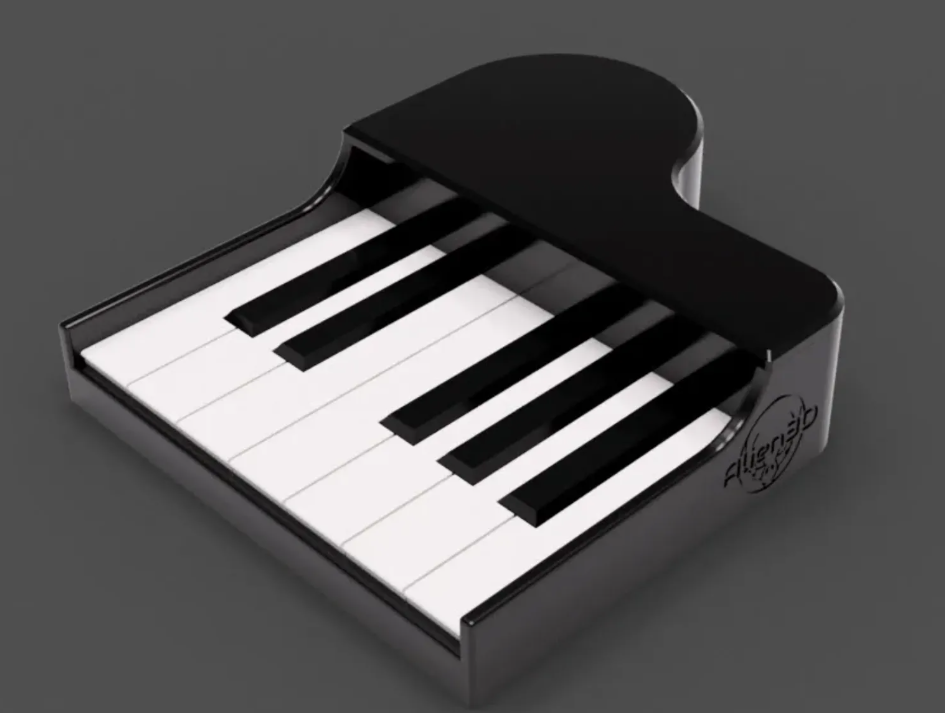
But, I need it to have 4 keys, so I am going to see if I can somehow alter the design to be for 4 keys instead of these 7 and also add a hole for the wires to come out from. I also anticipate the timing of the keys with the p5 to be hard. Firstly, there is often a delay between the arduino and the p5 I noticed when using the potentiometer in one of our assignments and that could mess up my game. Secondly, creating the tiles to fall in sync with an audio will be difficult and time consuming. I may just make it so that the tiles fall randomly, even if it is not in sync with the music. The game mechanics will still work like usual though.
Concept
For the final project I’ll be building a color memory game where the user sees colors generated at random by p5js and tries to match the colors by pressing arcade push buttons in the same order. And it gets tough as the game progresses. Every time the user gets it right a two-tiered trolley moves forward. The goal is to make the trolley/toy move as far as possible and close to the finish line within a short period of time.
Arduino and p5js
There will be serial communication between arduino and p5js in relaying the information concerning the color pressed (in arduino) against what has been displayed (on p5js) randomly. If there is a correct match between the two communication is sent back to the arduino to move the trolley forward. If not the p5js repeats the same pattern of colors previously displayed. There will also be a timer on the p5js screen to show the amount of time spent by the player.
This requires some explanation:
Originally, I had a well-fleshed-out idea for the use of motion sensors to play a volleyball game. While conceptually sound, in practice, the motion sensors just could not cooperate. After a lot of testing with Arduino and its sensors, I realized that the ball would move too quick for the sensors to process properly. Instead, I decided to make a violin.
The main mechanism in charge of producing sound will be a potentiometer, in such a way that when a bowstring is pulled back and forth, the potentiometer dial shall turn. Its analog output will be sent to p5, and detecting the bow’s movement will power a synthesizer to play sound. Next, the violin will have digital output buttons. Holding down buttons will give the arduino digital outputs also sent to p5. In p5, detecting which button is being pressed down will turn into a specific note in the scale. each of the 8 buttons represents one note, forming a full scale. This allows us to get a functional violin.
It’s Crossy Road gone fairy-tale: guide an on-screen duck across busy roads and small streams in p5.js. Reach the final, wide river and a real-world duck glides straight across a tabletop “river,” lights pulsing as a victory lap. Screen and reality shake hands for one perfect moment
| Module | Done | Notes |
|---|---|---|
| full screen canvas, road- rivers, predators, food | ✅ | 60 fps, collision OK( still needs work) |
| Duck sprite + full-axis movement | ✅ | Arrow keys for now |
| Item counter + score/time keeping | ✅ | only counted through codes so far |
| Final-river trigger zone | ✅ | logic works |
Real-World Interaction (Planned)
Prop: duck on a 30 cm linear rail (continuous-rotation servo + belt).
Motion: one smooth back to front glide only.
FX: underside RGB LED strip (water glow) + small piezo “quack” sample.
Cue: begins the instant p5 fires DUCK_GO and stops at rail limit.
Thinking of using the Arduino as the go-between that lets the computer game talk to the real duck. A little joystick and one “hop” button plug into it; the board simply reads how far you push the stick and whether the button is pressed, then sends those numbers to p5.js through the USB cable every split-second. Most of the time the Arduino just listens. When the game finally says “DUCK_GO”, the board springs into action: it turns on a motor that slides the rubber duck straight across a mini track, switches on soft blue-green lights under the “water,” and makes a quick quack with a tiny speaker. When p5.js later sends “DUCK_STOP,” the motor and lights shut off and the duck stays put. Because motors and lights can gulp a lot of power all at once, they’ll run from their own plug-in adapter so the Arduino itself never loses juice mid-move.
Prototype rail — mount servo + belt, confirm straight glide
Minimal Arduino sketch — joystick; act on DUCK_GO with LED blink
Serial bridge live — replace console.log() with serial.write() in p5
End-to-end smoke test — finish level, duck moves
Servo overshoot → limit switches or timed cutoff.
Serial lag → short packets, high baud.
Scope creep → no extra rivers, no particle splashes until core loop is solid.
Commit to your Final Project Proposal, include the following explanations in your blog post:
The finalized concept for my project is essentially an experimental simulation which visualizes the specific heart-rate pattern of the person interacting with it, produces experimental music in coordination with that data representation in real-time, and allowing for the user to interact with the simulation.
Serial connection: From arduino to p5.js. (one way)
Links for music (not mine) and if time allows, I might create my own music, but this is the current set of ambient and experimental music:
https://cdnjs.cloudflare.com/ajax/libs/p5.js/1.4.2/p5.min.js
https://cdnjs.cloudflare.com/ajax/libs/tone/14.8.49/Tone.min.js
function mousePressed() {
  for (let btn of buttons) {
    if (mouseX > btn.x && mouseX < btn.x + btn.w && mouseY > btn.y && mouseY < btn.y + btn.h) {
      if (btn.action === "back") {
        currentSeqIndex = (currentSeqIndex - 1 + sequences.length) % sequences.length;
        sequence.stop();
        sequence = new Tone.Sequence((time, note) => {
          arpSynth.triggerAttackRelease(note, "16n", time);
          polySynth.triggerAttackRelease([note, note + "2"], "2n", time);
          shapes.push({
            x: random(width),
            y: random(height),
            size: random(50, 150),
            sides: floor(random(3, 8)),
            hue: (bpm + currentSeqIndex * 60) % 360,
            rot: 0,
            type: currentSeqIndex % 2 ? "polygon" : "circle"
          });
        }, sequences[currentSeqIndex], "4n");
        if (!buttons[1].paused) sequence.start(0);
      } else if (btn.action === "pause") {
        btn.paused = !btn.paused;
        btn.label = btn.paused ? "Play" : "Pause";
        if (btn.paused) {
          Tone.Transport.pause();
        } else {
          Tone.Transport.start();
          sequence.start(0);
        }
      } else if (btn.action === "forward") {
        currentSeqIndex = (currentSeqIndex + 1) % sequences.length;
        sequence.stop();
        sequence = new Tone.Sequence((time, note) => {
          arpSynth.triggerAttackRelease(note, "16n", time);
          polySynth.triggerAttackRelease([note, note + "2"], "2n", time);
          shapes.push({
            x: random(width),
            y: random(height),
            size: random(50, 150),
            sides: floor(random(3, 8)),
            hue: (bpm + currentSeqIndex * 60) % 360,
            rot: 0,
            type: currentSeqIndex % 2 ? "polygon" : "circle"
          });
        }, sequences[currentSeqIndex], "4n");
        if (!buttons[1].paused) sequence.start(0);
      }
    }
  }
}
To emphasize the user interaction and fine-tune the functionality, the mouse pressed function alters the algorithm in which the music is produced.
I faced several issues with this TypeError:
I am currently using a placeholder variable for the input (heart rate) from this pulseSensor. The reason for that is that I need to solder the piece on the right (the metal wires) to create a connection so that I may connect the arduino to the pulseSensor. I am not experienced with soldering and I will ask for further help to continue this stage.

Next Step: My next step is to solder the wires and to start testing the sensor and implement it into the project. From this, I will test which patterns I can identify to produce the required data visualization. This is a large part of the project so at the current phase it is 30% complete.
Here is my p5.js so far, with a working and interactive algorithm to select preferred ambient music, and functionality based on the heart rate (simulated and dummy variable controlled with slider).
For the arduino uno, I will use this code:
#include <PulseSensorPlayground.h>
#include <ArduinoJson.h>

const int PULSE_PIN = A0;
const int BTN1_PIN = 2;
const int BTN2_PIN = 3;
const int BTN3_PIN = 4;

PulseSensorPlayground pulseSensor;
StaticJsonDocument<200> doc;

void setup() {
  Serial.begin(9600);
  pulseSensor.analogInput(PULSE_PIN);
  pulseSensor.setThreshold(550);
  pulseSensor.begin();

  pinMode(BTN1_PIN, INPUT_PULLUP);
  pinMode(BTN2_PIN, INPUT_PULLUP);
  pinMode(BTN3_PIN, INPUT_PULLUP);
}

void loop() {
  int bpm = pulseSensor.getBeatsPerMinute();
  if (!pulseSensor.sawStartOfBeat()) {
    bpm = 0; // Reset if no beat detected
  }

  doc["bpm"] = bpm;
  doc["btn1"] = digitalRead(BTN1_PIN) == LOW ? 1 : 0;
  doc["btn2"] = digitalRead(BTN2_PIN) == LOW ? 1 : 0;
  doc["btn3"] = digitalRead(BTN3_PIN) == LOW ? 1 : 0;

  serializeJson(doc, Serial);
  Serial.println();

  delay(100); // Send data every 100ms
}
and I will test it and document my progress in debugging as well.
Design considerations of the physical presentation of the project:
I am still thinking through different forms of cases, designs such as bracelets or medical tape to make the connection between the sensor and the person interacting with the program.
The design requires technical consideration, as the connection between the sensor and the radial artery would be already slightly weak (with a margin of error) I need to document this as well and consider my design after the implementation of the pulseSensor.
For the buttons, I am planning to make them on some form of platform (something similar to the platform that the breadboard and arduino are attached to.
Fullscreen for the best experience.
Plant Whisperer is a physical-digital interaction system that lets a real plant express how it feels through a friendly digital avatar. Using Arduino Uno and p5.js, the system monitors the plant’s environment, specifically light exposure and human interaction, and translates this data into visual and auditory feedback.
I want to promote awareness of nature and care through playful, intuitive technology. It reimagines how we perceive and respond to non-verbal living things by giving the plant a way to “talk back.”
Photoresistor (Light Sensor): Detects ambient light around the plant.
Capacitive Touch Sensor – DIY (using the CapacitiveSensor library): Detects when the user interacts with the plant.
RGB LED: Shows the plant’s current emotional state in color.
Piezo Buzzer: Plays tones based on mood or user interaction.
Avatar Behavior (in p5.js)
The avatar is a stylized digital plant that changes facial expression, movement, background color, and plays ambient sounds based on the sensor input.
Inspiration
![]()
| Sensor Input | Mood | Visual in p5.js | LED Color | Sound |
|---|---|---|---|---|
| Bright Light | Happy | Smiling plant, upright | Green | Gentle chime |
| Dim Light | Sleepy | Drooping plant, closed eyes | Blue | Soft drone |
| Very Low Light | Sad | Frowning plant, faded color | Purple | Slow tone |
| Button Pressed | Excited | Eyes sparkle, leaf wiggle | Yellow flash | Upbeat trill |
My goal with this project is to encourage mindfulness, care, and emotional engagement with the environment. By giving a non-verbal living organism a digital voice, the system fosters empathy and attention.
This project is about more than just monitoring a plant, it’s about interaction. By gently blurring the line between organic life and digital expression, Plant Whisperer invites users to slow down, observe, and connect with their environment through technology.
The project is a bomb defusal puzzle box, consisting of four mini-games that must be solved in sequence to reveal a 4-digit defusal code. Each completed challenge unlocks one digit of the code. After all four digits are revealed, the player must input the code correctly to determine which wire to “cut” to defuse the bomb.
The gameplay is immersive and pressure-driven, combining speed, precision, memory, and logic.
The 4 Challenges
1. Button Mash
Tap a button exactly 24 times as fast as possible so that user can move onto next challenge without wasting too much time. Encourages rhythm and pressure timing and serves as a warmup game for users as well.
2. Math Lock
A simple math problem appears on screen. The user selects their answer by turning a potentiometer. A confirm button locks in the answer. Feedback is given through p5.js on correctness.
3. Note Match
A musical note (from 4 pitches) is played using a buzzer. The player uses one of four buttons to play and listen to notes. When confident, the player presses a confirm button to lock in their selection. Visual feedback shows which note they selected.
4. Morse Code
A Morse code pattern ( with dots and dashes) representing a letter is shown briefly on screen. The user recreates the pattern using . and – through short and long presses of a button and then lock in their answer using a designated confirm button
Inputs:
Buttons: 4 buttons which will be multipurpose and serve as options for the various challenges and one button which will act as confirmation button and users will use it to lock in their answer.
Potentiometer: For Math Lock answer selection.
Outputs:
Buzzer: For Note Match playback.
Serial Communication: Sends current state/selections to p5.js.
Arduino to p5.js:
Selections (0–3 for Note Match/Math Lock)
Dot/dash inputs during Morse Code
Tap count for Button Mash
“CONFIRM” for challenge submission
p5.js to Arduino:
Math problem and options
Correct note index
Target Morse code sequence
Challenge start triggers
Visuals and Logic – p5js
1. Rendering challenge screens
2. Displaying math problems, notes, and Morse codes
3. Receiving real-time input signals via serial
4. Confirming answers and unlocking digits
5. Displaying progress toward final defusal
After all 4 digits are unlocked, p5 transitions to a final code entry stage:
– The player enters the 4-digit code
– If correct, p5 shows which colored wire to cut (physically implemented via clip wire/jumpers)
– If incorrect, p5 gives a failure message
For my final project, I am making an interactive reaction and memory game. The game will use physical components connected to an Arduino to play the game. It is inspired by retro games like Dance Dance Revolution. The project will challenge users to memorize and repeat increasingly complex light patterns using a diamond-shaped controller layout (similar to a DDR board). With each round, the sequence will grow longer, which will test the user’s memory and reaction speed.
Arduino Input/Output:
Inputs:
Output:
P5:
Design:
Game Logic:
Serial Communication:
Whats yet to be done:
Making the graphics to be used on the P5 screen (start screen, end screen, arrows), and finalising the code for each of the game states