The p5.js environment has been successfully designed, I went from a 2D version to a 3D avatar rendered in WEBGL. The system also includes a custom font and a wooden background platform for visual warmth. A floating instruction frame appears at the beginning of the interaction, prompting users to “press to start.”
The Arduino hardware components (photoresistor, DIY capacitive touch sensor, LEDs, and buzzer) are currently in the process of being tested. I am actively working on matching sensor input with the avatar’s behavior (e.g., face expression, sound).
Generally, my testing went okay, though because I had not given instructions I think, though, my design was pretty intuitive in such. way I think they got what they were supposed to do. Because my project had to do with modulating sound, the feedback is pretty instantaneous, and because there was not objective, really, users could just mess around with what you can do and really quickly get the hang of it. I am still working on adding an instructions screen on p5, though. I think an easy instructions page would provide all the information people will need to do with my project, just explaining what the different controllers on my cat thing do to the sound.
This project explores how tangible physical interactions can be mapped to dynamic digital feedback using basic electronics and browser-based programming. The goal was to create an accessible, playful, and immersive musical instrument by combining capacitive touch sensing with 3D visuals and synchronized audio. Built using an Arduino Uno and a p5.js sketch, the outcome is an interactive interface where touching conductive pads triggers audiovisual responses on screen and plays musical notes through the browser.
Concept and Design
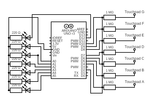
The project was inspired by the layout and playability of a traditional piano. Seven capacitive touchpads were arranged horizontally to simulate seven musical keys, each corresponding to a note from A to G. These touchpads were constructed from copper tape and wired to the Arduino using 1MΩ resistors and the CapacitiveSensor library, with digital pin D2 as the send pin and D4–D10 as receive pins. Touching a pad activates a signal sent via serial communication to a p5.js sketch running in the browser.
Visually, the p5.js interface features a WEBGL canvas with seven 3D cubes spaced evenly across a horizon-like scene. When a user touches one of the physical pads, the corresponding cube rotates, scales up, and releases a short burst of animated particles. Each key also triggers a distinct .mp3 file that plays the associated note. To complete the feedback loop, an LED mounted next to each pad lights up on activation, enhancing the physical response.
Implementation and Technical Challenges
The Arduino side of the system uses the CapacitiveSensor library for reliable touch detection. Serial data is transmitted using Serial.println() to send a numerical value (1 to 7) to the browser. These numbers are received in p5.js using the Web Serial API. Each value maps to a cube on the canvas, a sound file, and an LED output. Due to the limited number of digital pins on the Arduino Uno, analog pins A0–A5 were repurposed as digital outputs for controlling LEDs, alongside digital pin D12.
One major technical hurdle was encountered when attempting to load all sound files within a loop in p5.js using loadSound(). This approach caused the browser to silently fail to load the audio. The issue was resolved by loading each sound file individually, using separate loadSound() calls with explicit success and error handlers.
Another issue involved unstable serial communication, particularly when switching between the Arduino IDE and browser. Ensuring the serial monitor was closed before running the p5.js sketch, introducing delays in the Arduino setup() function, and adding robust error handling in the JavaScript code helped address this. Additionally, adding a 1MΩ pull-down resistor from pin D2 to GND improved signal reliability.
User Testing and Feedback
To evaluate the interface, I conducted informal user testing without providing any instructions. Users were able to understand the instrument’s function immediately due to its intuitive piano-like layout. Most could successfully trigger both audio and visuals without any guidance.
However, two issues emerged. First, the interface only featured seven keys, which users noticed as an incomplete octave. This design limitation was due to hardware constraints and the number of available input pins on the Arduino. Second, users reported a small but perceptible delay between touching the pad and hearing the sound, which slightly detracted from the interactive experience. Despite these drawbacks, users found the interface fun and engaging, and appreciated the multi-sensory feedback through visuals, sound, and lights.
Reflection
Overall, the project succeeded in creating a satisfying and creative interactive system that blends physical computing with browser-based media. The integration of touch, sound, and 3D visuals offered a cohesive and enjoyable user experience, demonstrating how simple hardware and software tools can be used to build meaningful interactions.
There are several areas for potential improvement. Adding an eighth key would allow users to play a full musical scale, which would greatly improve the musicality of the instrument. Reducing latency between touch and audio playback, possibly by optimizing serial reading or switching to a faster communication protocol, would also enhance responsiveness. Finally, some users have noted during the showcase that it would have been more interesting if piano keys could be pressed simultaneously. My personal vision for this project is making it gamified: when the cubes light up on the screen, inviting the user to plays corresponding keys to reproduce a certain song or melody.
Software: Arduino IDE, Chrome browser, p5.js Web Editor
Languages: C++ (Arduino), JavaScript (p5.js)
Conclusion
This project showcases how physical and digital systems can be seamlessly integrated to create interactive, expressive instruments. By leveraging capacitive sensing, serial communication, and browser technologies, the Capacitive Touch Musical Interface offers a compelling example of creative technology that invites play, experimentation, and multisensory engagement.
let port;
let reader;

let sounds = {};
let labels = ['A', 'B', 'C', 'D', 'E', 'F', 'G'];
let musicNotes = ['C', 'D', 'E', 'F', 'G', 'A', 'B'];
let allLoaded = false;

let cubeSizes = {};
let targetSizes = {};
let cubeRotations = {};
let targetRotations = {};
let flippedState = {};
let cubeYOffsets = {};
let targetYOffsets = {};
let particles = [];

let baseSize = 50;
let pulseSize = 100;
let jumpHeight = 40;

let sizeLerpSpeed = 0.2;
let rotationLerpSpeed = 0.15;
let positionLerpSpeed = 0.2;

let labelLayer;

function preload() {
  soundFormats('mp3');
  for (let label of labels) {
    sounds[label] = loadSound(`${label}.mp3`,
      () => console.log(` Loaded ${label}.mp3!`),
      err => console.error(`❌ Failed to load ${label}.mp3`, err)
    );
  }
}

function setup() {
  createCanvas(1000, 500, WEBGL);
  noStroke();

  labelLayer = createGraphics(width, height);
  labelLayer.textAlign(CENTER, CENTER);
  labelLayer.textSize(16);
  labelLayer.textFont('sans-serif');
  labelLayer.fill(20);

  for (let label of labels) {
    cubeSizes[label] = baseSize;
    targetSizes[label] = baseSize;
    cubeRotations[label] = 0;
    targetRotations[label] = 0;
    flippedState[label] = false;
    cubeYOffsets[label] = 0;
    targetYOffsets[label] = 0;
  }

  let connectButton = createButton("Connect to Arduino");
  connectButton.size(200, 40);
  connectButton.position((windowWidth - 200) / 2, height + 40);
  connectButton.class("connect-button");
  connectButton.mousePressed(connectToArduino);
}

function draw() {
  background(135, 206, 250);

  camera(0, -100, 600, 0, -100, 0, 0, 1, 0);

  push();
  translate(0, 100, 0);
  rotateX(HALF_PI);
  fill(220);
  plane(3000, 3000);
  pop();

  push();
  translate(0, 0, -1000);
  fill(135, 206, 250);
  plane(3000, 2000);
  pop();

  ambientLight(100);
  pointLight(255, 255, 255, 0, -300, 300);
  directionalLight(200, 200, 200, -0.5, -1, -0.3);

  let spacing = 120;
  let totalWidth = spacing * (labels.length - 1);
  let startX = -totalWidth / 2;

  for (let i = 0; i < labels.length; i++) {
    let label = labels[i];

    cubeSizes[label] = lerp(cubeSizes[label], targetSizes[label], sizeLerpSpeed);
    cubeRotations[label] = lerp(cubeRotations[label], targetRotations[label], rotationLerpSpeed);
    cubeYOffsets[label] = lerp(cubeYOffsets[label], targetYOffsets[label], positionLerpSpeed);

    let x = startX + i * spacing;
    let y = -baseSize / 2 + 100 - cubeYOffsets[label];

    push();
    translate(x, y, 0);
    rotateX(cubeRotations[label]);
    fill(0, 102, 204);
    specularMaterial(0, 102, 204);
    shininess(20);
    box(cubeSizes[label]);
    pop();
  }

  for (let i = particles.length - 1; i >= 0; i--) {
    particles[i].update();
    particles[i].display();
    if (particles[i].lifespan <= 0) particles.splice(i, 1);
  }

  labelLayer.clear();
  for (let i = 0; i < musicNotes.length; i++) {
    let spacing = 120;
    let totalWidth = spacing * (labels.length - 1);
    let x = -totalWidth / 2 + i * spacing;
    let screenX = width / 2 + x;
    let screenY = height / 2 + 130;
    labelLayer.text(musicNotes[i], screenX, screenY);
  }

  resetMatrix();
  image(labelLayer, 0, 0);
}

function triggerCube(label) {
  targetSizes[label] = pulseSize;
  targetYOffsets[label] = jumpHeight;
  setTimeout(() => {
    targetSizes[label] = baseSize;
    targetYOffsets[label] = 0;
  }, 150);
  flippedState[label] = !flippedState[label];
  targetRotations[label] = flippedState[label] ? PI : 0;

  let spacing = 120;
  let totalWidth = spacing * (labels.length - 1);
  let x = -totalWidth / 2 + labels.indexOf(label) * spacing;
  let y = 100 - baseSize;

  for (let i = 0; i < 15; i++) {
    particles.push(new Particle(x, y, 0));
  }
}

function keyPressed() {
  let keyUp = key.toUpperCase();
  if (sounds[keyUp]) {
    sounds[keyUp].play();
    triggerCube(keyUp);
  }
}

async function readSerial() {
  while (port.readable) {
    try {
      const decoder = new TextDecoderStream();
      const inputDone = port.readable.pipeTo(decoder.writable);
      const inputStream = decoder.readable;
      const reader = inputStream.getReader();

      while (true) {
        const { value, done } = await reader.read();
        if (done) {
          console.warn(" Serial stream ended. Trying to reconnect...");
          reader.releaseLock();
          break;
        }
        if (value) {
          const clean = value.trim().toUpperCase();
          console.log(" Received from Arduino:", clean);
          if (sounds[clean]) {
            sounds[clean].play();
            triggerCube(clean);
          }
        }
      }
    } catch (err) {
      console.error("❌ Serial read error:", err);
      break;
    }

    await new Promise(resolve => setTimeout(resolve, 1000));
  }

  console.log("❌ Serial not readable anymore.");
}

async function connectToArduino() {
  try {
    port = await navigator.serial.requestPort();
    await port.open({ baudRate: 9600 });
    readSerial();
    console.log("✅ Serial connected");
  } catch (err) {
    console.error("❌ Connection failed:", err);
  }
}

class Particle {
  constructor(x, y, z) {
    this.pos = createVector(x, y, z);
    this.vel = createVector(random(-1, 1), random(-3, -1), random(-0.5, 0.5));
    this.lifespan = 60;
  }

  update() {
    this.pos.add(this.vel);
    this.vel.y += 0.05;
    this.lifespan -= 2;
  }

  display() {
    push();
    translate(this.pos.x, this.pos.y, this.pos.z);
    fill(255, 150, 0, this.lifespan * 4);
    noStroke();
    sphere(5);
    pop();
  }
}
Arduino code:
#include <CapacitiveSensor.h>

// CapacitiveSensor(sendPin, receivePin)
CapacitiveSensor pads[7] = {
  CapacitiveSensor(2, 4),  // A
  CapacitiveSensor(2, 5),  // B
  CapacitiveSensor(2, 6),  // C
  CapacitiveSensor(2, 7),  // D
  CapacitiveSensor(2, 8),  // E
  CapacitiveSensor(2, 9),  // F
  CapacitiveSensor(2, 10)  // G
};

const char notes[7] = {'A', 'B', 'C', 'D', 'E', 'F', 'G'};
bool touched[7] = {false};

int ledPins[7] = {A0, A1, A2, A3, A4, A5, 12};  // LED output pins

long threshold = 100;  // Adjust after testing raw values

void setup() {
  delay(1000);  // Allow time for USB/Serial to stabilize
  Serial.begin(9600);

  for (int i = 0; i < 7; i++) {
    pads[i].set_CS_AutocaL_Millis(0xFFFFFFFF); // Disable autocalibration
    pinMode(ledPins[i], OUTPUT);
    digitalWrite(ledPins[i], LOW);
  }
}

void loop() {
  for (int i = 0; i < 7; i++) {
    long reading = pads[i].capacitiveSensor(10); // Reduced samples for speed
    bool isTouched = (reading > threshold);

    digitalWrite(ledPins[i], isTouched ? HIGH : LOW);

    if (isTouched && !touched[i]) {
      Serial.println(notes[i]);
      touched[i] = true;
    } else if (!isTouched && touched[i]) {
      touched[i] = false;
    }
  }

  // No delay(5); loop runs as fast as possible for lower latency
}
For my final project, I had my friend Taif and few others test out my Arduino-based bomb defusal game. Overall, the feedback was quite positive and also highlighted some good areas for improvement.
All of the players were able to figure out the core mechanics pretty quickly. The buttons worked smoothly and felt responsive. Most people could navigate the game on their own without much explanation, which was great to see. The Button Smash, Note Match, and Morse Code modules were especially well-received and fun for the players.
One thing that confused some users was the Math Riddle module. The instructions weren’t as clear for that one, such as how to choose the answer, and players weren’t sure what to do at first. Another part that could be improved is the final code entry step – it wasn’t obvious to everyone when or how they were supposed to enter it.
Some suggestions I got were:
Add better instructions at the start for each game or stage.
Make the countdown more dramatic and obvious with more frequent or intense LED flashing near the end.
Things to be implemented : LED lighting for more visual feedback and a more visible timer, also I feel l might reduce the overall time to solve the puzzles since users usually finished before the time ran out quite easily.
Even though some elements weren’t implemented yet, the players enjoyed the concept and the tension of the timer. Overall, user testing helped me find small tweaks to make the game smoother and more fun.
This project was inspired bythe retro Etch-A-Sketch with a modern twist. Instead of knobs, individuals control the drawing with two potentiometers (for X and Y movement) and a switch for toggling between drawing states. Individuals were tasked withexploring interactive hardware-software integration by translating analog sensor input into graphical visual output. After hearing questions and feedback, I aim to further improve real-time drawing accuracy and the user interface by reducing latency, refining the toggle function, and thinkingabouthow to betterintuitively represent drawing progress.
Utilization of the [p5.webserial] library facilitated the reading of serial data from the Arduino without the need for desktop software.
Potentiometers were providing accurate analog input, and mapping to screen coordinates was achieved after calibration.
Intuitive buttons for starting, connecting/disconnecting the port, and resetting the canvas make the experience even more seamless.
A new drawing color is created with each button push, creating a fun and dynamic drawing experience.
Additional Improvement
Provide on-screen instructions on how to connect to the Serial monitor
Provide instructions and indicators on the model itself (indicators of the potentiometers and button)
Make a small hole for the USB Type-B cable to pass through, to prevent messiness
Add a little cover over the model to cover up the wires in the arduino board
The earlier versions exhibited clear lag or delay when drawing. This was addressed by optimizing serial communication and removing the [multiple.readUntil()] calls within the draw loop.
The initial drawing of the red cursor was removed to avoid the distraction it caused from the artwork. It was ultimately removed for relying on the user to sense movement with the potentiometer.
Still some minor jitter or lag on switching draw mode. Adding smoothing or filtering noise would likely enhance accuracy.
The mode switch from welcome screen to the drawing view functions but may appear polished visually in usability terms for a better user experience.
Future ideas
Add an on-screen cursor to show position without drawing.
Add a on-screen button to save the drawing as a PNG.
Berry Blessings is an Arduino joystick-controlled p5.js game where a duck must collect 10 berries to unlock a magical portal to the real world. Once the player reaches the portal, an Arduino-powered robot is meant to activate and move toward a fairy setup, creating a double world experience.
After receiving feedback that the previous storyline was too abstract and difficult to understand, I redesigned the narrative to be more intuitive and enjoyable. The new version provides a clear goal which is collecting berries to unlock a portal and eventually a satisfying real-world reward.
Two users participated in a no-instruction playtest of the p5.js portion of the game.
What Worked Well
Joystick Controls: Users figured out joystick movement after some experimentation. Movement felt smooth once they adjusted to it.
Berry Counter: The on-screen “Berries: X / 10” counter gave clear feedback and helped users understand progression.
Visual Design: The duck animations, bright environment, and sign reading “Collect 10 berries to pass” helped anchor the gameplay and made objectives more understandable.
Revised Storyline: The updated goal and real-life payoff made the experience feel more engaging and easier to follow.
Challenges & Observations
Joystick Direction Mapping: Both users were initially confused by which way the duck would move relative to joystick direction.
Planned fix: Add visual direction indicators (e.g. arrows or compass).
Robot Frustration (During Earlier Testing): Friends testing the robot portion before the Arduino broke reported frustration with its slow, unstable movement.
Plan: Replace with a more reliable wheeled robot for smoother performance.
Duck Centering Bug: One user pointed out that the duck appeared too far from the center when changing directions.
Fix: Adjusted duck positioning to remain centered during direction changes.
Hardware Damage: The Arduino Uno was accidentally damaged due to adjusting connections while powered on, so it could not be used during this round of user testing.
Fixes & Next Steps
Already Implemented:
Rewrote the story to improve clarity and engagement.
Added a sign by the portal to explain the berry objective.
Included a working berry counter.
Fixed duck position offset when changing directions.
In Progress:
Sourcing a new Arduino Uno to replace the damaged one.
Planning to switch to a wheeled robot for improved reliability.
Will add visual joystick direction indicators to help users orient themselves.
I will post an update before next class once the hardware is replaced and re-integrated.
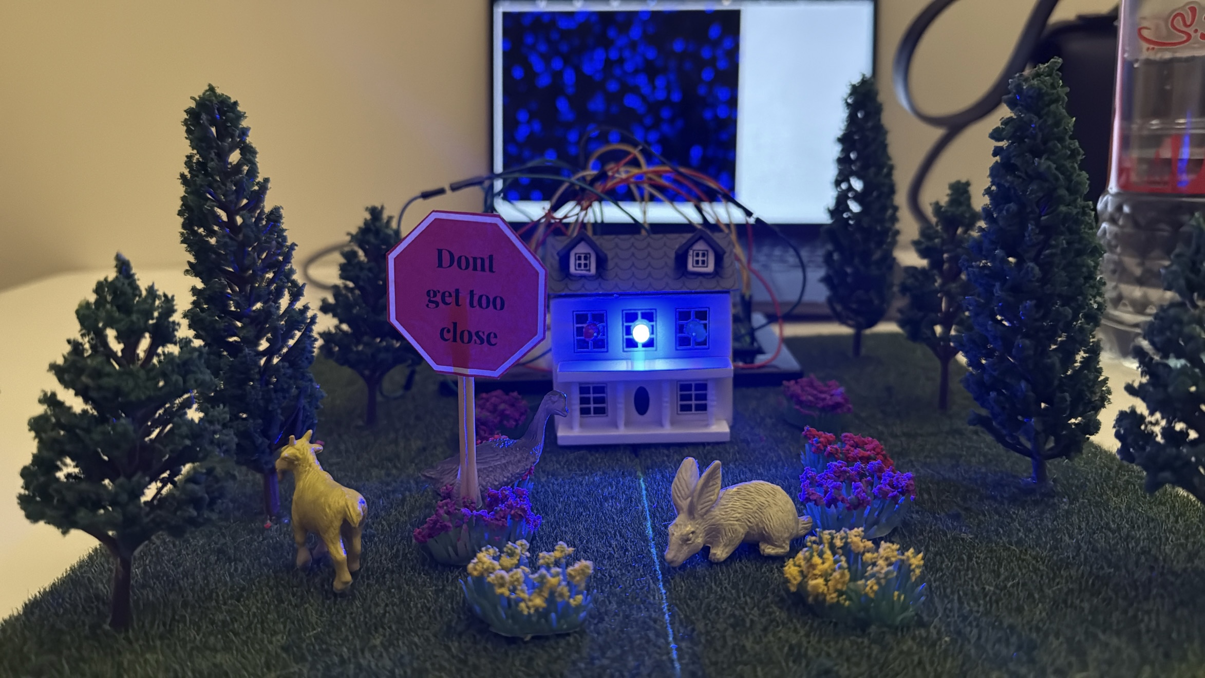
This project was inspired by a real experience on my family’s farm—I saw foxes approaching our chickens at night, and my dad was complaining on how to deal with the situotion it made me think about how to create a simple way to detect movement at a low cost and respond immediately. I wanted something that could work without constant supervision, so I came up with the idea of using an ultrasonic sensor and lights to react when something gets close.
From there, I built a mini garden setup using individual RGB LEDs and connected it to P5.js for visual feedback. I started with a different idea—using sound and an LED strip—but changed direction after facing hardware limitations. and honestly I love how it turned better. That process helped shape the final concept,i also wanted to create something similar to lava lamps that’s why ii ended up doing the visuals in p5.js similar to the blobs in the lava lamps which now works as both an interactive installation and a practical assistive device for animal and crop protection.
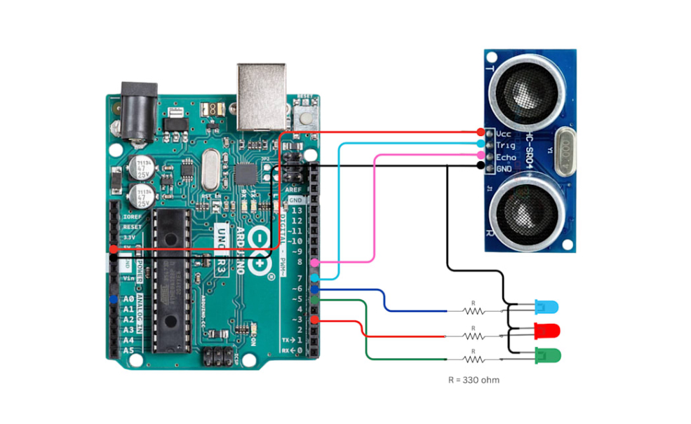
My final project is the Motion-Activated Mini Garden/farm Visualizer, an interactive installation that responds to movement and presence using an ultrasonic sensor. – house and the garden I built . When someone approaches the garden, the LEDs light up based on proximity—closer movement causes brighter, more vibrant lights, while standing farther away results in dimmer, calmer effects.
// HC-SR04 Ultrasonic Sensor Pins
#define TRIG_PIN 7
#define ECHO_PIN 8

// RGB LED Pins
#define RED_LED_PIN 3
#define GREEN_LED_PIN 5
#define BLUE_LED_PIN 6

long duration;
int distance;

void setup() {
  Serial.begin(9600);

  // Sensor Pins
  pinMode(TRIG_PIN, OUTPUT);
  pinMode(ECHO_PIN, INPUT);

  // RGB LED Pins
  pinMode(RED_LED_PIN, OUTPUT);
  pinMode(GREEN_LED_PIN, OUTPUT);
  pinMode(BLUE_LED_PIN, OUTPUT);

  turnOffAll(); // Ensure LEDs are off initially
}

void loop() {
  // Trigger the ultrasonic sensor
  digitalWrite(TRIG_PIN, LOW);
  delayMicroseconds(2);
  digitalWrite(TRIG_PIN, HIGH);
  delayMicroseconds(10);
  digitalWrite(TRIG_PIN, LOW);

  // Read echo and calculate distance (cm)
  duration = pulseIn(ECHO_PIN, HIGH);
  distance = duration * 0.034 / 2;

  // Print distance to serial
  // Serial.print("Distance: ");
  Serial.println(int(distance));
  // Serial.println(" cm");

  // LED logic based on distance
  if (distance < 10) {
    setColor(255, 0, 0);   // Close → Red
  }
  else if (distance >= 10 && distance <= 30) {
    setColor(0, 255, 0);   // Medium → Green
  }
  else {
    setColor(0, 0, 255);   // Far → Blue
  }
  delay(100);
}

// Control RGB LEDs using digital logic
void setColor(uint8_t r, uint8_t g, uint8_t b) {
  digitalWrite(RED_LED_PIN, r > 0 ? HIGH : LOW);
  digitalWrite(GREEN_LED_PIN, g > 0 ? HIGH : LOW);
  digitalWrite(BLUE_LED_PIN, b > 0 ? HIGH : LOW);
}

void turnOffAll() {
  digitalWrite(RED_LED_PIN, LOW);
  digitalWrite(GREEN_LED_PIN, LOW);
  digitalWrite(BLUE_LED_PIN, LOW);
}
p5.js code:
let serial;
let distance = 0;

function setup() {
  createCanvas(windowWidth, windowHeight);
  background(0);

  serial = new p5.SerialPort();
  serial.on('connected', () => console.log("Connected to Serial!"));
  serial.on('data', serialEvent);
  serial.open("/dev/tty.usbmodem101"); // Change to your actual COM port
  console.log();
}

function draw() {
  background(0, 30);

  // let size = map(distance, 0, 1023, 10, 100); // Adjust if your micValue goes up to 1023
  let size = 30;
  let col;
  if (distance < 10) {
    col = color(255, 0, 0); // Low
  } else if (distance < 30) {
    col = color(0, 255, 0); // Medium
  } else {
    col = color(0, 0, 255); // High
  }

  fill(col);
  noStroke();

  for (let i = 0; i < 20; i++) {
    ellipse(random(width), random(height), size);
  }
}


function serialEvent() {
  let data = serial.readLine().trim();
  if (data.length > 0) {
    distance = int(data);
    console.log("mic:", distance);
  }
}
A short clip showing someone approaching the mini garden. As they move closer, the LED lights respond by changing color, and the screen displays animated, color-shifting blobs in sync with the movement:
An ultrasonic sensor detects how close a person or object is to the garden. This distance value is read by the Arduino and mapped to RGB LED colors. The same data is also sent over serial communication to P5.js, which animates abstract blobs on the screen. These blobs shift in speed, size, and color based on how close the user is, creating a consistent and engaging visual language that mirrors the physical lighting
interaction design :
The design of the project relies on intuitive interaction. Users are not given instructions—they are simply invited to explore. As they move closer to the garden, the changes in light and digital visuals guide them to understand the system’s behavior. This makes the experience playful and discoverable.
Distance from Sensor
LED Color
P5.js Visual Response
Less than 10 cm
Red
Fast motion, bright red blobs
10–30 cm
Green
Medium speed, green blobs
More than 30 cm
Blue
Slow, soft blue motion
A clear explanation focusing on how the device assists with animal and crop protection,
Assistive Use Cases: Protecting Animals and Crops:
This motion-activated system has strong potential as an assistive device in agricultural and animal care settings, where clear and reliable response is essential.
For Animals (Livestock Protection):
The system can be used to monitor the area around livestock enclosures such as sheep pens, chicken coops, or goat fields. When a predator like a fox, stray dog, or wild animal approaches, the ultrasonic sensor detects motion, triggering an immediate response—such as flashing lights, alarms, or future-connected alerts. This helps deter predators non-invasively and gives farmers real-time awareness of threats without being physically present.
For Crops (Field and Garden Monitoring):
In gardens, greenhouses, or open crop fields, this system can be used to detect intruders, trespassers, or large animals that may damage crops. The lights act as a deterrent, and with future improvements (like wireless communication), it could alert the farmer via phone or connected system. This is especially helpful at night or in remote locations, allowing for continuous, low-maintenance monitoring.
Assistive Use Case: Law Enforcement and Security
This motion-activated system can be effectively adapted for law enforcement and security by serving as a low-cost, responsive perimeter monitoring tool. Installed at property lines, remote checkpoints, or restricted access areas, the device detects unauthorized movement and can trigger lights, sirens, or silent alerts depending on the situation. With future enhancements, it could be linked to mobile devices or integrated with camera systems for real-time surveillance. Its compact, portable design makes it suitable for temporary deployments during investigations, search operations, or event monitoring, offering a clear and reliable response without requiring continuous human oversight.
what im proud of :
Creating a synchronized experience between physical light and digital visuals
Making the interaction intuitive and inviting, even without instructions
Learning how to connect Arduino to P5.js and achieve stable real-time communication
Areas of improvement
Add wireless communication (e.g., Bluetooth or Wi-Fi) to trigger mobile alerts
Improve the physical build by embedding LEDs into real plants or creating a more polished enclosure
Include a reset or mode switch to allow the user to cycle through different animation types
To evaluate the user experience of ExpressNotes, I conducted testing sessions where participants interacted with the system without receiving any instructions or guidance. The goal was to observe how intuitive the system is and identify any points of confusion. Users were introduced to the setup with the Arduino buttons, potentiometer, and the connected P5.js visual interface on a laptop. Most users hesitated at the beginning, unsure of how to begin the interaction, with the “Connect to Arduino” button being overlooked by several participants.
Once the connection was established and users began pressing buttons, they quickly recognized that each button triggered a unique piano note along with a visual effect on the screen. This immediate feedback created a sense of play and curiosity, and users began experimenting more confidently. The relationship between physical input and audiovisual output was generally clear, although the specific mappings between notes and visuals were not always understood without further exploration or explanation.
The potentiometer was another area where users expressed confusion. While some participants guessed that it controlled volume, others assumed it affected brightness or visual intensity. The lack of on-screen feedback for the potentiometer made its purpose harder to identify. Adding a visual indicator—such as a dynamic volume bar—could significantly improve clarity and reinforce the connection between the physical control and the system’s response.
One common suggestion from users was to enhance the physical design of the interface. Several participants mentioned that the Arduino board and buttons looked too technical or unfinished. They recommended covering the board with a piano-style overlay so the buttons resemble piano keys. This would not only make the device more visually appealing but also give immediate context to new users, helping them understand that the interaction is musically driven.
ExpressNotes was well received as an interactive and expressive experience. Users enjoyed the audio-visual feedback and were intrigued by how the visual patterns changed with each note. However, clearer onboarding, labels for controls, a visual volume indicator, and improved hardware presentation would help users engage more quickly and confidently. These observations will guide improvements to make the project more accessible, intuitive, and enjoyable for first-time users.
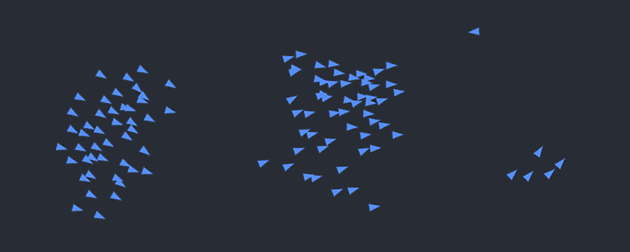
For my final project, I developed an interactive flocking simulation that users can control through hand gestures captured via their webcam. The project uses computer vision and machine learning to detect and interpret hand positions, allowing users to manipulate a swarm of entities (called “boids”) by making specific hand gestures.
The core concept was to create an intuitive and embodied interaction between the user and a digital ecosystem. I was inspired by the natural behaviors of flocks of birds, schools of fish, and swarms of insects, and wanted to create a system where users could influence these behaviors through natural movements.
User Testing Insights
During user testing, I observed people interacting with the system without providing any instructions. Here’s what I discovered:
Most users initially waved at the screen, trying to understand how their movements affected the simulation
Users quickly discovered that specific hand gestures (pinching fingers) changed the shape of the swarming elements
Some confusion occurred about the mapping between specific gestures and shape outcomes
Users enjoyed creating new boids by dragging the mouse, which added an additional layer of interactivity
Areas where users got confused:
Initially, people weren’t sure if the system was tracking their whole body or just their hands
Some users attempted complex gestures that weren’t part of the system
The difference between the thumb-to-ring finger and thumb-to-pinkie gestures wasn’t immediately obvious
What worked well:
The fluid motion of the boids created an engaging visual experience
The responsiveness of the gesture detection felt immediate and satisfying
The changing shapes provided clear feedback that user input was working
The ability to add boids with mouse drag was intuitive
Interaction (p5 side for now):
The P5.js sketch handles the core simulation and multiple input streams:
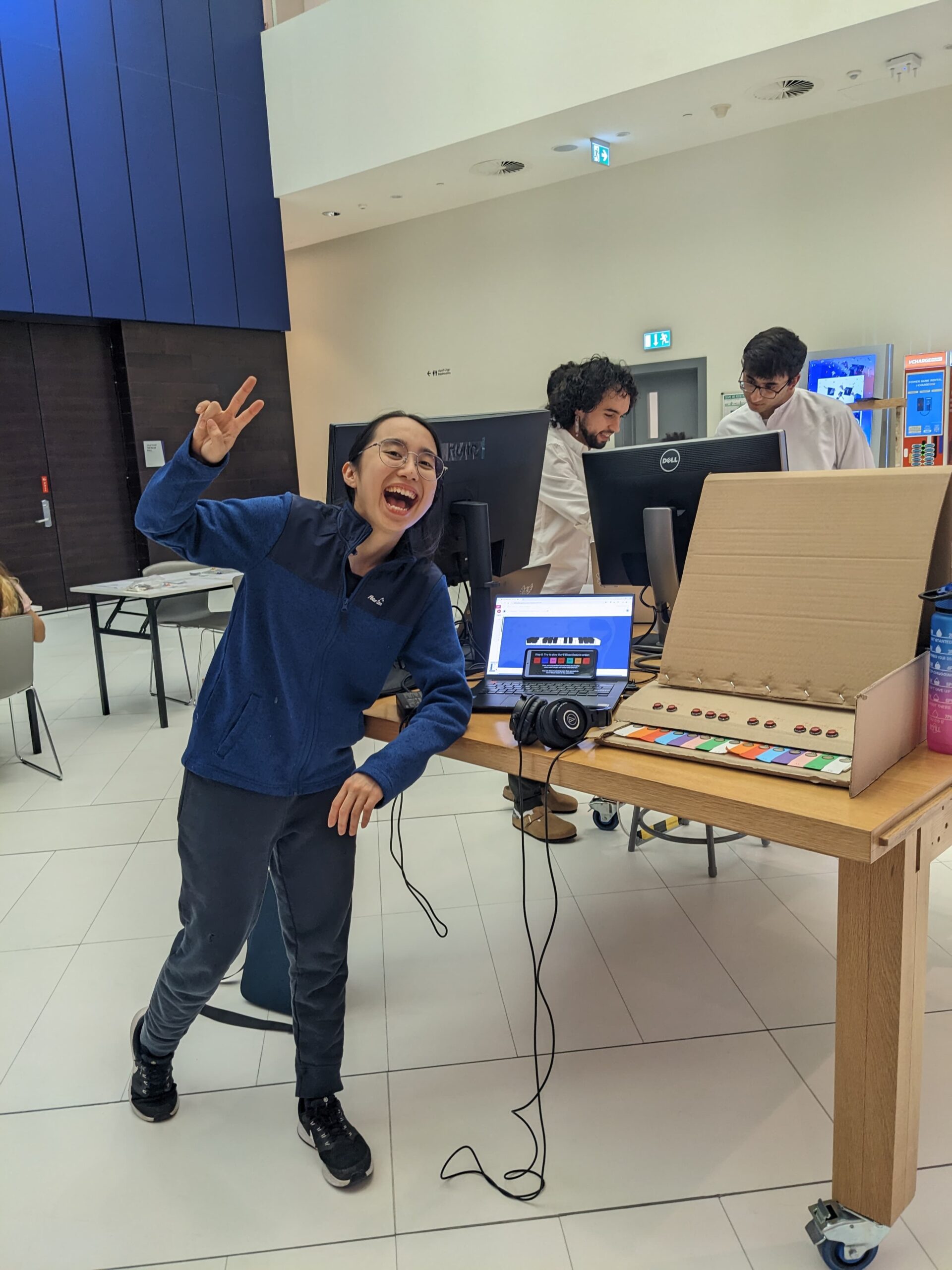
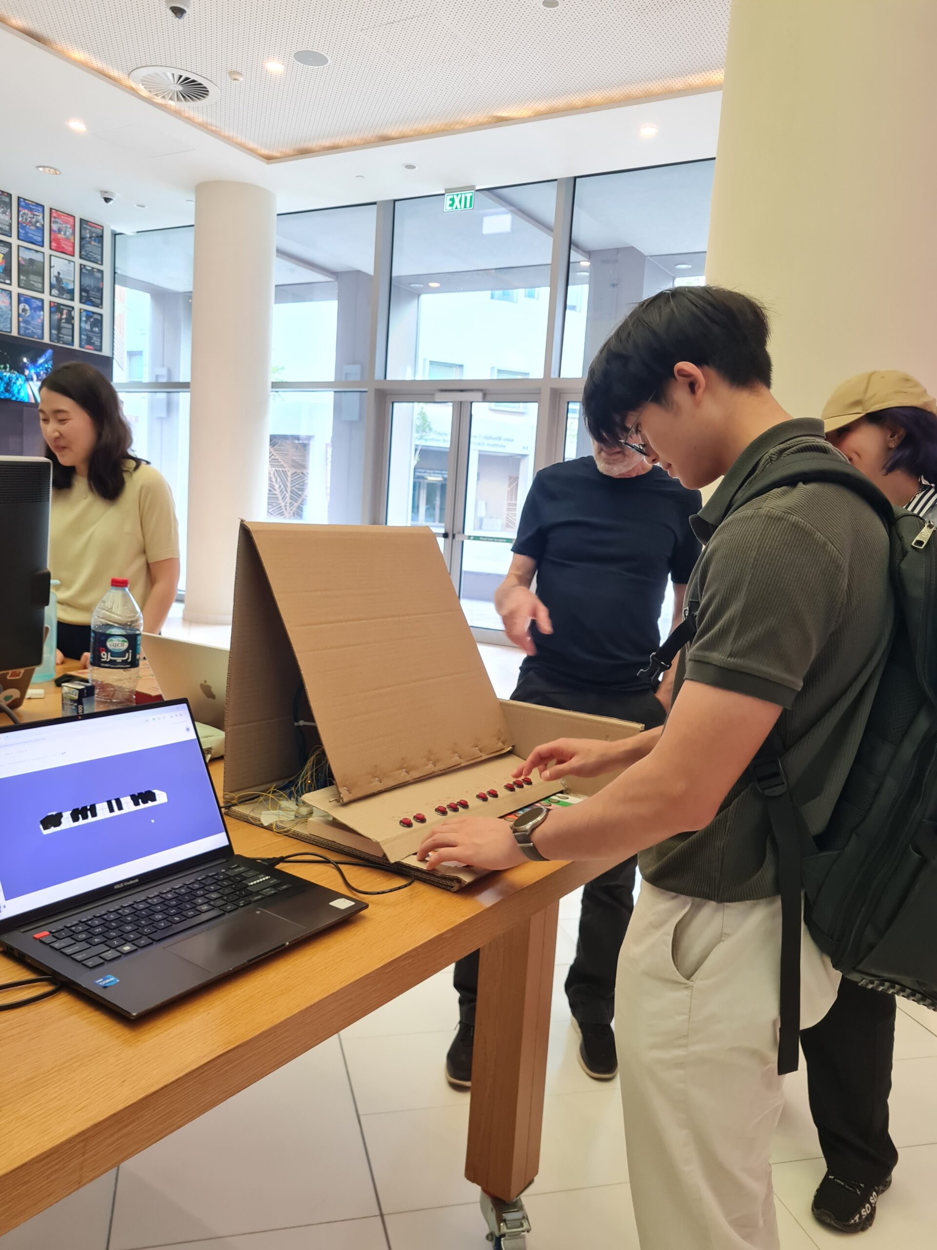
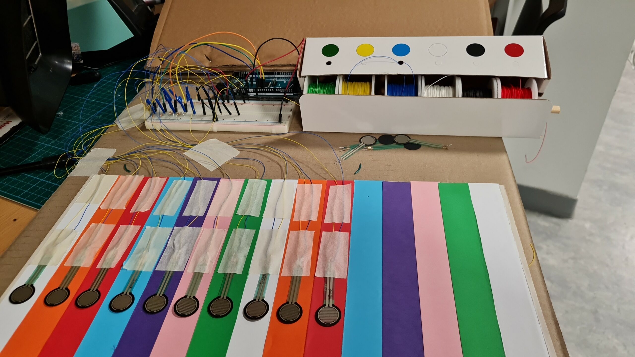
My final project helps users, especially beginners, to learn how to play the piano and learn how to jam to the blues music style. I created a mini-piano consisting of 2 octaves plus one key (spanning notes C4 to C6), which is a welcoming size for beginners. A visualization of a piano is displayed on the p5js sketch, which can be helpful for the piano player to see an animated pressed key and listen to the relevant audio for that pressed key.
Product with Animation Display and Headphones
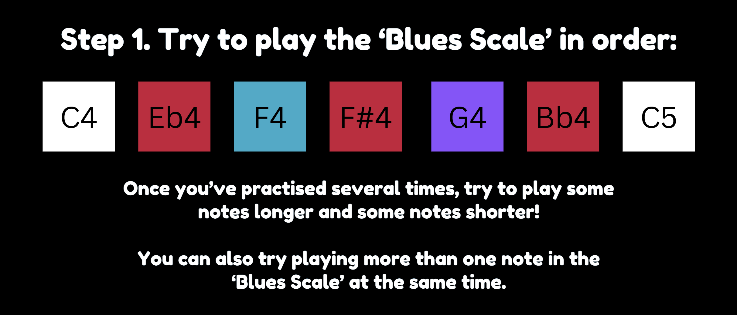
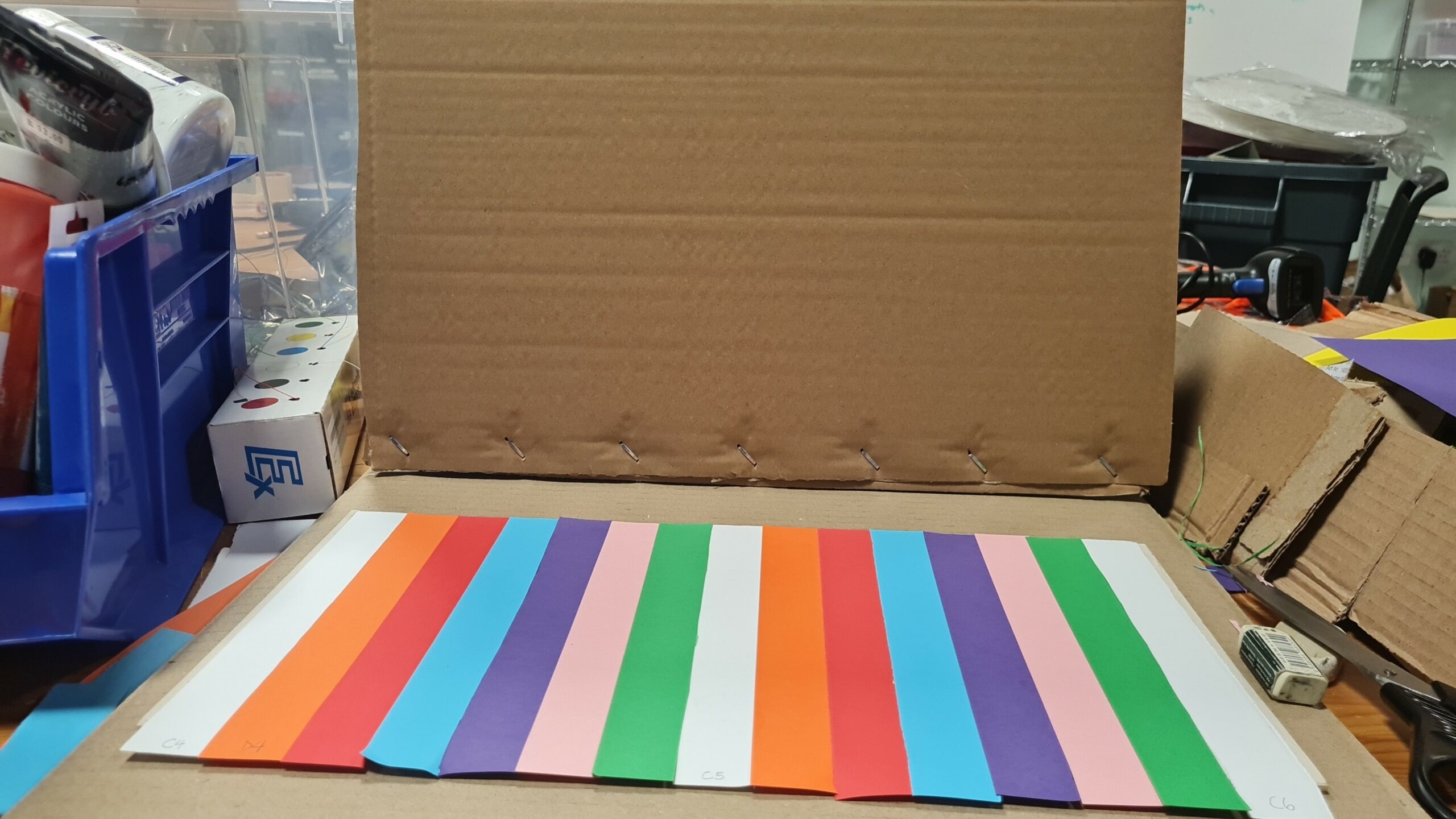
The piano is color-coded by note, so that note “C” is white, “D” is orange, “E” is red, “F” is blue and so on. This was a deliberate choice because seeing different colours on the piano can help users familiarize themselves with the positions of the keys over time. Additionally, I used this presentation slide deck with instructions to play the notes, color-coded, in order (example in Fig. 1). Thus, as users see the color-coded notes on the presentation and try to follow it, they could more quickly and easily match it to the note on the physical piano that they should play.
Fig. 1. Instructions to Play, In Left-Right Order, the Color-Coded Notes
2. Pictures / Videos of Project Interaction
3. Implementation
The interaction design can be described as follows: users can listen to an E-minor backing track, and respond by pressing on the labelled force sensitive resistors and labelled push buttons, resulting in an animation of pressed white keys vs pressed black keys respectively. They also hear the note being played using p5js.
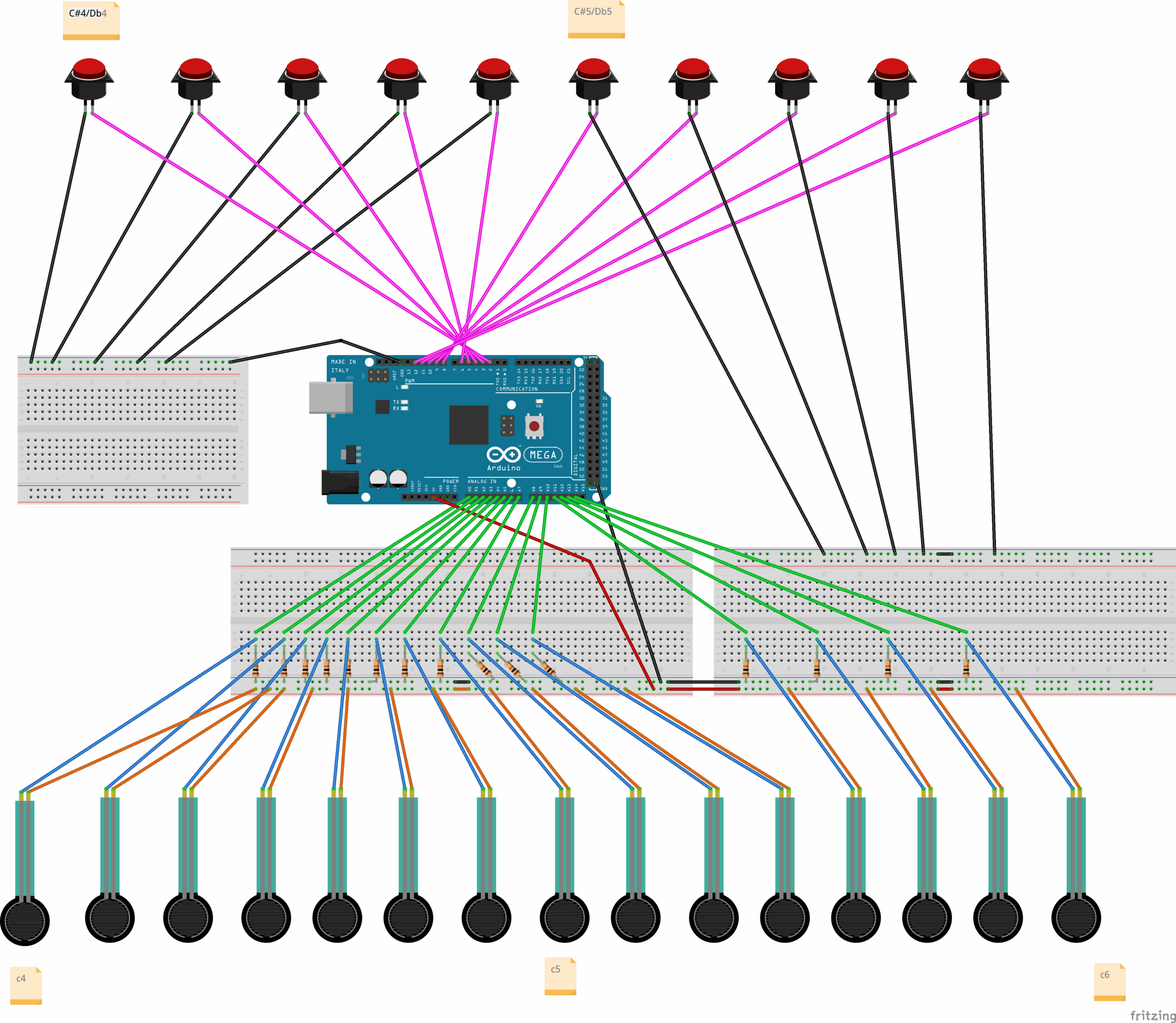
For hardware, I deliberately used an Arduino MEGA for its sufficient provision of analog pins. I used pins A0 to A14 for the force sensitive resistors and pins 2-6 as well as 8-12 for the push buttons. The schematic is attached.
Schematic
For software, both Arduino software and p5js are used, with a one-way communication from Arduino to p5js. My Arduino sketch is linked here and my p5js sketch is linked here.
Notably, in addition to defining fsrPins and buttonPins arrays, theArduino code has string arrays “whiteKeyNames,” “blackKeyNames” as well as boolean arrays “whiteKeyPressedState” and “blackKeyPressedState” which stores the last sent state (true if pressed, false if released). The setup() function initializes the arrays. In the loop() function, white keys are processed with hysteresis, checking:
IF FSR reading is above the press threshold but its pressed state was off before, currentActualStateIsPressed is TRUE
IF FSR reading is above the release threshold and its pressed state was on before, currentActualStateIsPressed is TRUE
ELSE IF FSR reading is not beyond the release threshold, currentActualStateIsPressed is FALSE
For stability, the black keys are processed with debouncing, which is about removing bouncing in contacts and delay is a timing feature.
Initially, I was inspired by this p5js template which uses WEBGL to create a 3D animation. In my case, orbitControl is enabled, allowing rotation and zooming in and zooming out. Notably, arrays of audio files (whiteKeyAudioFiles and blackKeyAudioFiles) as well as arrays of piano key objects (whiteKeyObjects and blackKeyObjects) help my code be concise and easier to manage. For organization purposes, “WhiteKey” class is stored in WhiteKey.js and “BlackKey” class is stored in BlackKey.js.
Using the template, I learned how to generate the animation: use an initial white key x-position (initial_wk_x = -375), set a white key spacing (white_key_spacing = 50) since they are spaced evenly on a real piano, and set dedicated black key x-positions [-350, -300, -200, -150, -100, 0, 50, 150, 200, 250]. Since I had more keys than the initial template, I had to edit the black key x-positions and the initial white key position.
In the communication from Arduino to p5, a string is sent line-by-line containing note name, followed by “=”, followed by note state (either 0 or 1 depending on if it’s considered pressed or not). activeSerialNoteStates is an important variable that stores the latest state (0 or 1) received from Arduino for each note name. Based on the current state of a particular key in activeSerialNoteStates, the handlePressEvent() and display() for that key is called.
function readSerial(data) {
  if (data != null) {
    let parts = data.split("=");
    if (parts.length === 2) {
      let noteName = parts[0].trim();
      let noteState = parseInt(parts[1].trim()); // Will be 0 or 1

      // Store the latest state sent by Arduino for this note
      activeSerialNoteStates[noteName] = noteState;
      // console.log("Received: " + noteName + ", State: " + noteState); // For debugging
    }
  }
}
4. Great Aspects of the Project
In terms of design, I think the color-coded strips are important and helpful indicators that guide the user on where to press given an instruction:
Design Framework – Color-Coded Strips Pasted on Cardboard
Crucially, an important challenge I faced in the project was using attaching wire to the FSRs in a way that would not damage them. Initially, I damaged two FSRs in my attempt to wire them. However, over time, I became more familiar on how to use the wire wrapping tool. Combined with soldering, taping, and attaching the FSRs to the circuit, this entire process was time-consuming, perhaps taking about 8 hours. Taping is so important, to prevent metal conductors from different wires touching each other and making connections that should not be made.
Adding FSRs to Circuit using and Attaching Them to Breadboard using Wire Wrapping Tool
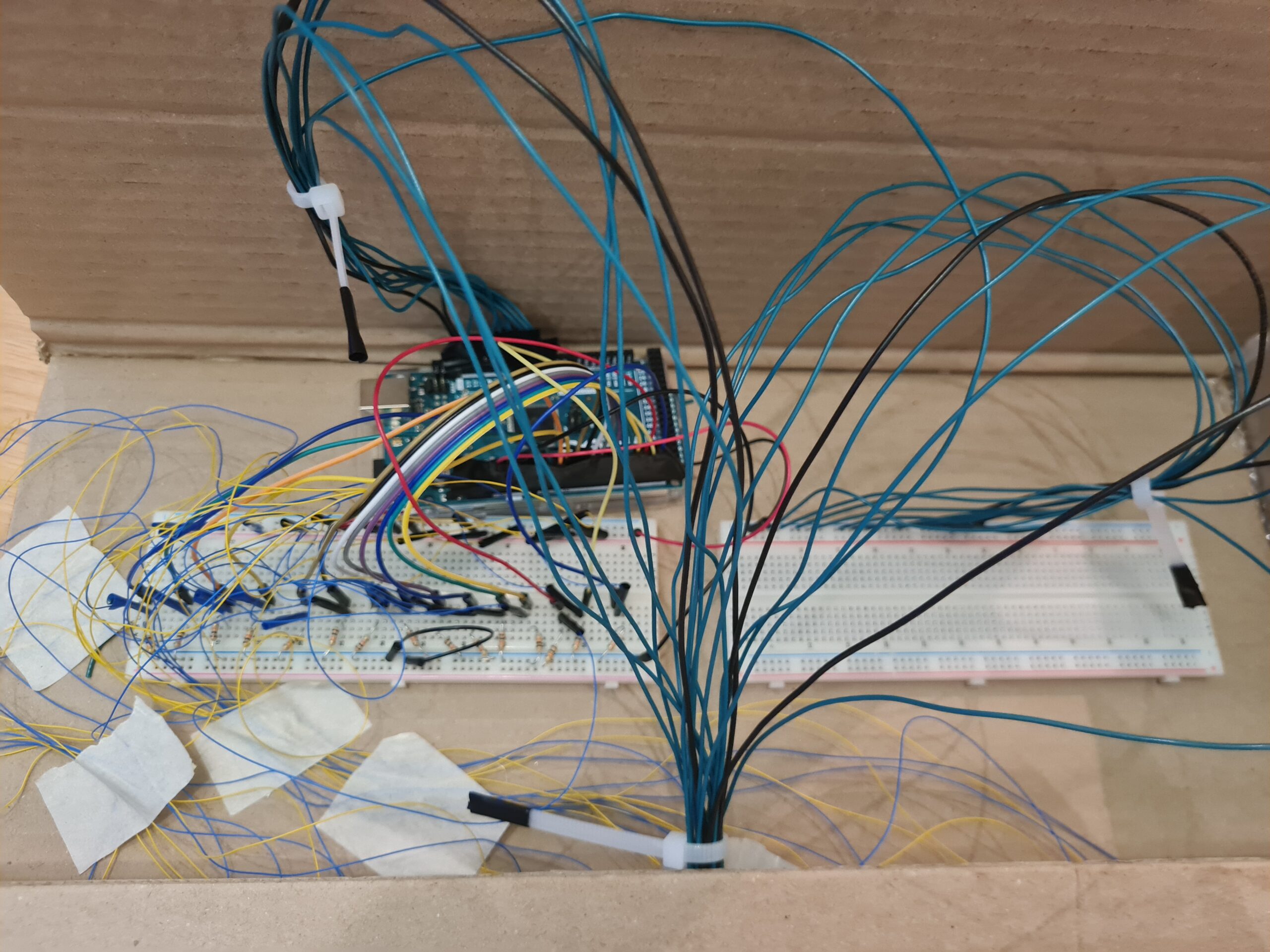
In terms of organization, the wires have been arranged neatly using a cable organizer:
Wires Arranged Neatly Using Cable Organizer
As for code, the preload() function helped important audio, including the backing track and the piano key sounds to be prepared before the animation so they could be played on time. Moreover, a very critical challenge I faced was slow sound feedback after a key press. In my attempt to resolve this, I thought of factors that could be the issue, such as animation having a huge load. Using AI recommendation, I tried to reduce the load by increasing lerp(…, …, 0.2) to lerp(…, …, 1) – even if animation would be less smooth. However, this only reduced the feedback delay very slightly – it was still noticeable. I thought more, and realized I could try having Arduino do the checks of the FSR readings over the press threshold and then send the note state to p5(0 or 1) – instead of having p5 do the checks. I tried to revise the code manually at first, but faced disfunctionality, and used AI to help me. After having Arduino do the checks, the feedback delay issue was resolved! Through this experience, I learned how Arduino truly specializes in input/output (at least compared to p5js) really emphasizing the Professor’s words in class.
In terms of audio choice, I chose recorded sounds of pressed keys of an old piano which has volume that decreases over time, instead of digital MIDI sounds, to mimic a real piano experience more closely.
5. Future Improvement
In the future, the project could be expanded by weaving both visual arts and music into an interactive art gallery with rooms containing a visual scene with background music. Unlike a traditional art gallery, this art gallery comes with an “escape room” challenge: each art room is a phase of an “escape room” challenge for which users must interact with through musical jamming to reach the next phase (or proceed to the next art room). Once all phases are passed, the user successfully completes the escape room challenge! In this way, users should interact with every artwork in the art gallery if they are to pass this “escape room” challenge.
User decisions can be enabled by analog/digital sensors. For example, users can control an avatar using joysticks to move up, right, left, or down within the escape room setting (eg. a big treehouse). The user should use clues involving the visual artwork and the musical sounds heard from p5js to figure out a solution that involves jamming in a corrected/accepted way to pass the phase and reach the next phase. The jamming could be through a “piano” made with force sensitive resistors (FSR), each connected to a buzzer. The connection of each FSR to a buzzer is crucial as it enables multiple musical notes to be heard at the same time.
One of my hopes I had for this project is to help music be more beginner friendly – to simplify musical complexity through visual pairing. Novice players often struggle with abstract musical concepts like chords and rhythm patterns. To address this, each puzzle should pair auditory elements with direct visual analogs that guide interactions without requiring prior musical knowledge.
Color-coded notes mapped to specific areas in the artwork 1
Animated rhythm indicators synced to musical phrases 2
Blending an interactive art gallery, an escape room, musical learning, and physical computing could have a lot of potential for an engaging and memorable experience – and perhaps even more research on it for musical learning!

 Aruidno code: