All Posts

Week 14 – Final Project

Flock Together: Gesture-Controlled Boids

Concept:

This interactive project brings the beautiful patterns of flocking behavior to life through a blend of digital and physical interactions. Drawing inspiration from Craig Reynolds’ classic Boids algorithm, the simulation creates an emergent collection of entities that move with collective “intelligence” (just like birds). What makes this implementation special is how it places control directly in your hands (literally).

Using hand tracking technology, you can shape the flock by pinching different fingers against your thumb: switch between triangles, circles, squares, and stars with your left hand, or adjust the flocking parameters with your right. The experience extends beyond the screen through an Arduino connection, where turning a physical knob changes the speed of the entire flock, and buttons let you add or remove boids in groups. The result is a meditative yet playful experience that bridges the digital and physical worlds, inviting you to explore how simple rules can create complex, beautiful patterns that respond intuitively to your gestures and touch.

Implementation Details:

I put together a fun web demo of Craig Reynolds’ Boids algorithm that you can actually mess with using your hands, your mouse, or even an Arduino knob. Behind the scenes there’s a Flock class full of little boids that follow separation, alignment, and cohesion rules you can tweak on the fly. You can choose triangles, circles, squares, or stars, and twist a physical potentiometer (via p5.webserial.js) to speed them up from half-speed to 5x, or hit “ADD” or “REMOVE” commands to add or remove 5 boids. In the browser, I use ML5.js’s HandPose model to spot pinch gestures, pinch with your left hand to swap shapes, pinch with your right to dial in the steering forces, and I run the video offscreen so everything stays buttery smooth. The canvas automatically resizes to fit your window, shows a chill gradient background that subtly reacts to your hardware tweaks, and even displays connection status and boid count. If hand tracking hiccups or the Arduino disconnects, it just auto-reconnects so the flock party never has to stop 🙂

Interaction Design:

The application uses ML5’s handpose detection to implement a natural gestural interface:

  1. Left Hand Controls Shape Selection:
    • Index finger + thumb pinch: Triangle shape (shape 0)
    • Middle finger + thumb pinch: Circle shape (shape 1)
    • Ring finger + thumb pinch: Square shape (shape 2)
    • Pinky finger + thumb pinch: Star shape (shape 3)
  2. Right Hand Controls Flocking Parameters:
    • Middle finger + thumb pinch: Increases separation force (from 1.5 to 8.0)
    • Ring finger + thumb pinch: Increases cohesion force (from 1.0 to 2.0)
    • Pinky finger + thumb pinch: Increases alignment force (from 1.0 to 2.0)

The gesture system uses a distance threshold of 20 pixels between finger and thumb to trigger actions, making the interaction intuitive and responsive.

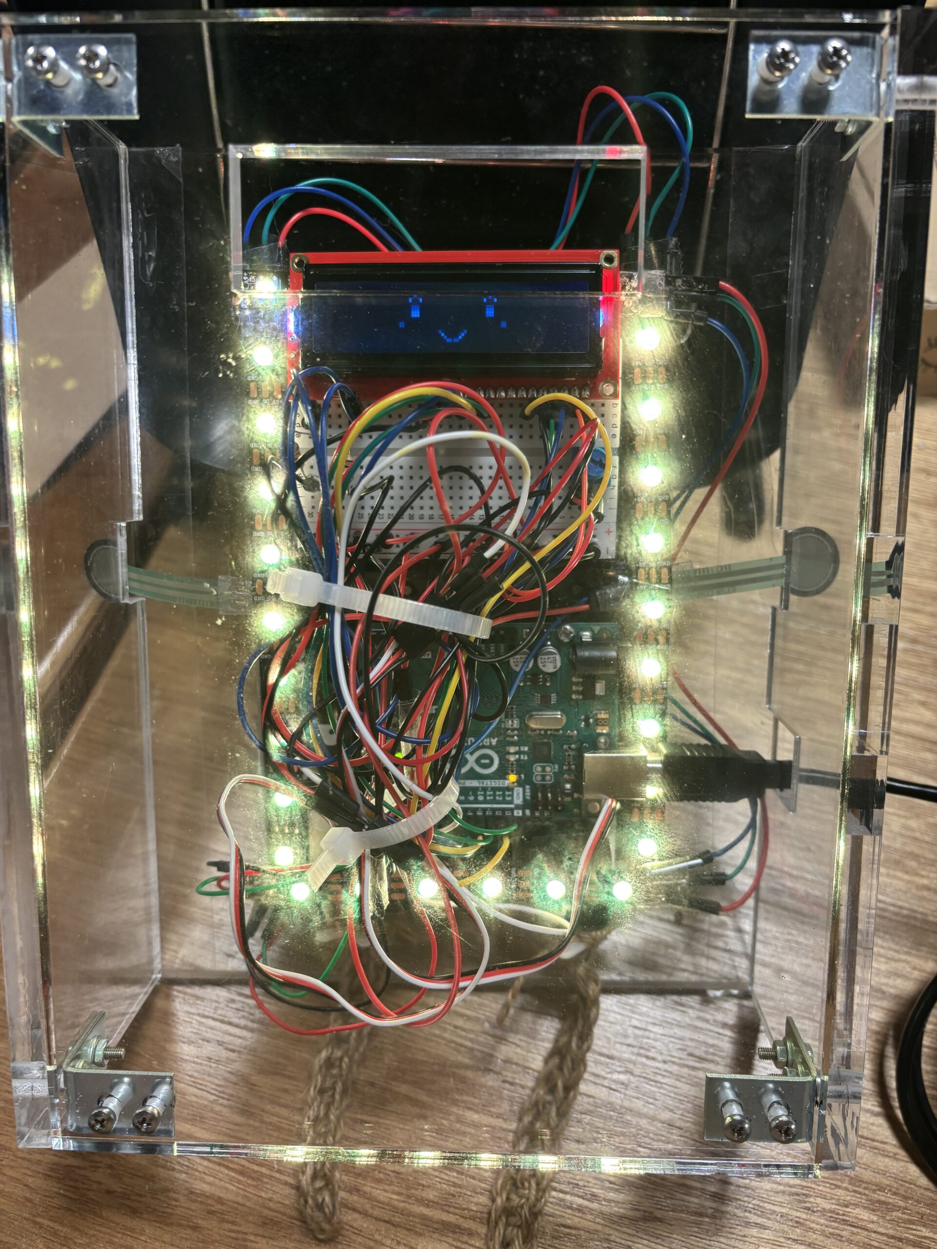
Physical Hardware Integration

The project incorporates an Arduino with physical controls:

  1. Potentiometer Input:
    • Controls the movement speed of the boids (mapped from 0.5 to 5.0)
    • Values from Arduino (0-1023) are normalized for smooth speed control
  2. Button Controls (inferred from serial messages):
    • “ADD” command: Adds 5 new boids to the simulation
    • “REMOVE” command: Removes 5 boids from the simulation

Serial Communcation:

The serial communication in this project connects the web application with an Arduino microcontroller using the p5.webserial.js library. In sketch.js, the app initializes a serial port (createSerial()) in the setupSerial() function and attempts to connect to previously used ports. When connected (indicated by the green indicator), the application receives two types of data: commands like “ADD” and “REMOVE” that control the boid population (adding or removing 5 boids at a time), and analog values from a potentiometer (0-1023) that control the speed of the boids. The potentiometer value is normalized (mapped to a range of 0.5-5) and applied to the flock’s movement speed via the flock.updateSpeed() method. Users can also manually connect to the Arduino by clicking on the screen if the connection indicator shows red. This bidirectional communication allows physical hardware to influence the digital flocking simulation in real-time.
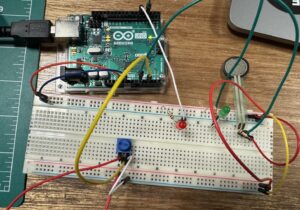
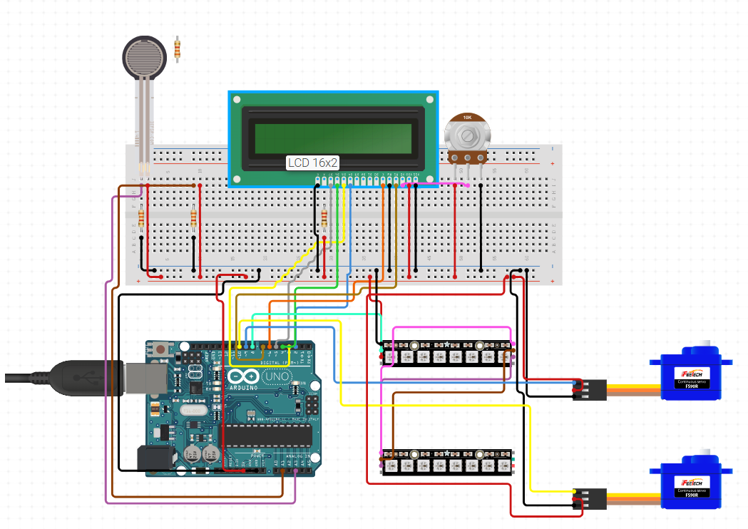
Schematic:

Arduino Code:

// Pin definitions
const int BUTTON_ADD_PIN = 2;     // Button to add boids
const int BUTTON_REMOVE_PIN = 3;  // Button to remove boids
const int POT_PIN = A0;           // Potentiometer for background color

// Variables to keep track of button states
int buttonAddState = HIGH;         // Current state of add button (assume pulled high)
int lastButtonAddState = HIGH;     // Previous state of add button
int buttonRemoveState = HIGH;      // Current state of remove button
int lastButtonRemoveState = HIGH;  // Previous state of remove button

// Variables for debouncing
unsigned long lastDebounceTime = 0;  
const unsigned long debounceDelay = 50;  // Debounce time in milliseconds

// Variable to store pot value
int potValue = 0;
int lastPotValue = -1;  // Store last pot value to detect significant changes

void setup() {
  // Initialize serial communication at 9600 bps
  Serial.begin(9600);
  
  // Set button pins as inputs with pullup resistors
  pinMode(BUTTON_ADD_PIN, INPUT_PULLUP);
  pinMode(BUTTON_REMOVE_PIN, INPUT_PULLUP);
  
  // No need to set analog pin mode for potentiometer
}

void loop() {
  // Read button states (LOW when pressed, HIGH when released due to pullup)
  int readingAdd = digitalRead(BUTTON_ADD_PIN);
  int readingRemove = digitalRead(BUTTON_REMOVE_PIN);
  
  // Check if add button state changed
  if (readingAdd != lastButtonAddState) {
    lastDebounceTime = millis();
  }
  
  // Check if remove button state changed
  if (readingRemove != lastButtonRemoveState) {
    lastDebounceTime = millis();
  }
  
  // Wait for debounce time to pass
  if ((millis() - lastDebounceTime) > debounceDelay) {
    // Update button states if they've changed
    if (readingAdd != buttonAddState) {
      buttonAddState = readingAdd;
      
      // If button is pressed (LOW), send command to add boids
      if (buttonAddState == LOW) {
        Serial.println("ADD");
      }
    }
    
    if (readingRemove != buttonRemoveState) {
      buttonRemoveState = readingRemove;
      
      // If button is pressed (LOW), send command to remove boids
      if (buttonRemoveState == LOW) {
        Serial.println("REMOVE");
      }
    }
  }
  
  // Read potentiometer value (0-1023)
  potValue = analogRead(POT_PIN);
  
  // Only send pot value if it changed significantly (to reduce serial traffic)
  if (abs(potValue - lastPotValue) > 10) {
    Serial.println(potValue);
    lastPotValue = potValue;
  }
  
  // Update last button states
  lastButtonAddState = readingAdd;
  lastButtonRemoveState = readingRemove;
  
  // Small delay to stabilize readings
  delay(10);
}

p5 code:

sketch.js:

let handPose;                            // ml5 HandPose model
const baseWidth = 1440;                  // reference canvas width
const baseHeight = 900;                  // reference canvas height
const shape = 0;                         // initial shape type (0–triangle)
                                           // 0 - triangle, 1 - circle, 2 - square, 3 - stars

let flock;                               // Flock instance
let video;                               // video capture
let port;                                // serial port
let serialConnected = false;             // serial connection flag
let potentiometerValue = 0;              // analog input from Arduino

// draw a star shape at (x,y)
function star(x, y, radius1, radius2, npoints) {
    let angle = TWO_PI / npoints;
    let halfAngle = angle / 2.0;
    beginShape();
    for (let a = 0; a < TWO_PI; a += angle) {
        // outer vertex
        vertex(x + cos(a) * radius2, y + sin(a) * radius2);
        // inner vertex
        vertex(x + cos(a + halfAngle) * radius1, y + sin(a + halfAngle) * radius1);
    }
    endShape(CLOSE);
}

class Flock {
    constructor() {
        this.boids = [];
        this.numBoids = 100;
        this.shape = shape;
        this.speedMultiplier = 1;
        this.separationWeight = 1.5;
        this.cohesionWeight = 1.0;
        this.alignmentWeight = 1.0;

        // initialize boids at random positions
        for (let i = 0; i < this.numBoids; i++) {
            this.boids.push(new Boid(random(width), random(height), this.shape));
        }
    }

    run() {
        // update each boid's behavior and render
        for (let boid of this.boids) {
            boid.run(this.boids, this.separationWeight, this.cohesionWeight, this.alignmentWeight);
        }
    }

    updateShape(shape) {
        this.shape = shape;
        // apply new shape to all boids
        this.boids.forEach(boid => boid.shape = shape);
    }

    updateSpeed(multiplier) {
        // constrain speed multiplier and update maxSpeed
        this.speedMultiplier = constrain(multiplier, 0.5, 5);
        this.boids.forEach(boid => boid.maxSpeed = 3 * this.speedMultiplier);
    }

    updateSeparation(weight) {
        // adjust separation weight
        this.separationWeight = constrain(weight, 0.5, 8);
    }

    updateCohesion(weight) {
        // adjust cohesion weight
        this.cohesionWeight = constrain(weight, 0.5, 3);
    }

    updateAlignment(weight) {
        // adjust alignment weight
        this.alignmentWeight = constrain(weight, 0.5, 3);
    }

    addBoid(boid) {
        // add a new boid
        this.boids.push(boid);
    }

    removeRandomBoid() {
        // remove one random boid if any exist
        if (this.boids.length > 0) {
            this.boids.splice(floor(random(this.boids.length)), 1);
        }
    }
}

class Boid {
    constructor(x, y, shape) {
        this.position = createVector(x, y);       // current location
        this.velocity = createVector(random(-1, 1), random(-1, 1));
        this.acceleration = createVector(0, 0);
        this.shape = shape;                       // shape type
        this.maxSpeed = 3;                        // top speed
        this.maxForce = 0.05;                     // steering limit
        this.r = 5;                               // radius for drawing
    }

    run(boids, separationWeight, cohesionWeight, alignmentWeight) {
        // flocking behavior, movement, boundary wrap, and draw
        this.flock(boids, separationWeight, cohesionWeight, alignmentWeight);
        this.update();
        this.borders();
        this.render();
    }

    applyForce(force) {
        // accumulate steering force
        this.acceleration.add(force);
    }

    flock(boids, separationWeight, cohesionWeight, alignmentWeight) {
        // calculate each flocking component
        let alignment = this.align(boids).mult(alignmentWeight);
        let cohesion  = this.cohere(boids).mult(cohesionWeight);
        let separation = this.separate(boids).mult(separationWeight);

        this.applyForce(alignment);
        this.applyForce(cohesion);
        this.applyForce(separation);
    }

    update() {
        // apply acceleration, limit speed, move, reset accel
        this.velocity.add(this.acceleration);
        this.velocity.limit(this.maxSpeed);
        this.position.add(this.velocity);
        this.acceleration.mult(0);
    }

    render() {
        // draw boid with correct shape and rotation
        let theta = this.velocity.heading() + radians(90);
        push();
        translate(this.position.x, this.position.y);
        rotate(theta);
        noStroke();
        fill(127);

        if (this.shape === 1) {
            circle(0, 0, this.r * 2);
        } else if (this.shape === 2) {
            square(-this.r, -this.r, this.r * 2);
        } else if (this.shape === 3) {
            star(0, 0, this.r, this.r * 2.5, 5);
        } else {
            // default triangle
            beginShape();
            vertex(0, -this.r * 2);
            vertex(-this.r, this.r * 2);
            vertex(this.r, this.r * 2);
            endShape(CLOSE);
        }

        pop();
    }

    borders() {
        // wrap around edges
        if (this.position.x < -this.r) this.position.x = width + this.r;
        if (this.position.y < -this.r) this.position.y = height + this.r;
        if (this.position.x > width + this.r) this.position.x = -this.r;
        if (this.position.y > height + this.r) this.position.y = -this.r;
    }

    separate(boids) {
        // steer away from close neighbors
        let perception = 25;
        let steer = createVector();
        let total = 0;

        boids.forEach(other => {
            let d = p5.Vector.dist(this.position, other.position);
            if (other !== this && d < perception) {
                let diff = p5.Vector.sub(this.position, other.position).normalize().div(d);
                steer.add(diff);
                total++;
            }
        });

        if (total > 0) steer.div(total);
        if (steer.mag() > 0) {
            steer.setMag(this.maxSpeed).sub(this.velocity).limit(this.maxForce);
        }
        return steer;
    }

    align(boids) {
        // steer to match average heading
        let perception = 50;
        let sum = createVector();
        let total = 0;

        boids.forEach(other => {
            let d = p5.Vector.dist(this.position, other.position);
            if (other !== this && d < perception) {
                sum.add(other.velocity);
                total++;
            }
        });

        if (total > 0) {
            sum.div(total).setMag(this.maxSpeed).sub(this.velocity).limit(this.maxForce);
        }
        return sum;
    }

    cohere(boids) {
        // steer toward average position
        let perception = 50;
        let sum = createVector();
        let total = 0;

        boids.forEach(other => {
            let d = p5.Vector.dist(this.position, other.position);
            if (other !== this && d < perception) {
                sum.add(other.position);
                total++;
            }
        });

        if (total > 0) {
            sum.div(total).sub(this.position).setMag(this.maxSpeed).sub(this.velocity).limit(this.maxForce);
        }
        return sum;
    }
}

function preload() {
    handPose = ml5.handPose();             // load handpose model
}

function setup() {
    createCanvas(windowWidth, windowHeight);     // full-window canvas
    video = createCapture(VIDEO);                // start video
    video.size(640, 480);
    video.style('transform', 'scale(-1, 1)');    // mirror view
    video.hide();
    handPose.detectStart(video, handleHandDetection); // begin hand detection
    flock = new Flock();                         // init flock

    setupSerial();                               // init Arduino comms
}

function draw() {
    drawGradientBackground();                    // dynamic background
    flock.run();                                 // update and render boids

    // read and handle serial input
    if (port && port.available() > 0) {
        let data = port.readUntil("\n")?.trim();
        if (data === "REMOVE") {
            for (let i = 0; i < 5; i++) flock.removeRandomBoid();
        } else if (data === "ADD") {
            for (let i = 0; i < 5; i++) flock.addBoid(new Boid(random(width), random(height), flock.shape));
        } else {
            potentiometerValue = parseInt(data);
            let norm = map(potentiometerValue, 0, 1023, 0, 1);
            flock.updateSpeed(map(norm, 0, 1, 0.5, 5));
        }
    }

    // display connection status and stats
    fill(serialConnected ? color(0,255,0,100) : color(255,0,0,100));
    noStroke();
    ellipse(25, 25, 15);
    fill(255);
    textSize(12);
    text(serialConnected ? "Arduino connected" : "Arduino disconnected", 40, 30);
    text("Boids: " + flock.boids.length, 40, 50);
    text("Potentiometer: " + potentiometerValue, 40, 70);
}

function windowResized() {
    resizeCanvas(windowWidth, windowHeight);   // adapt canvas size
}

function mouseDragged() {
    // add boid at drag position
    flock.addBoid(new Boid(mouseX, mouseY, flock.shape));
}

function mousePressed() {
    // connect to Arduino on click
    if (!serialConnected) {
        port.open('Arduino', 9600);
        serialConnected = true;
    }
}

function setupSerial() {
    port = createSerial();                     // create serial instance
    let usedPorts = usedSerialPorts();         // recall last port
    if (usedPorts.length > 0) {
        port.open(usedPorts[0], 9600);
        serialConnected = true;
    }
}

function drawGradientBackground() {
    // vertical gradient based on potentiometer
    let norm = map(potentiometerValue, 0, 1023, 0, 1);
    let c1 = color(0, 0, 0);
    let c2 = color(50, 50, 100);
    for (let y = 0; y < height; y++) {
        stroke(lerpColor(c1, c2, map(y, 0, height, 0, 1)));
        line(0, y, width, y);
    }
}

handGestures.js:

function handleHandDetection(results) {
    detectedHands = results;
    if (detectedHands.length === 0) return;

    let leftHandData = null;
    let rightHandData = null;

    // Identify left/right hands (using handedness or X position fallback)
    detectedHands.forEach(hand => {
        if (hand.handedness === 'Left') {
            leftHandData = hand;
        } else if (hand.handedness === 'Right') {
            rightHandData = hand;
        } else if (hand.keypoints[0].x > video.width / 2) {
            leftHandData = hand;
        } else {
            rightHandData = hand;
        }
    });

    if (leftHandData) handleShapeSelection(leftHandData);
    if (rightHandData) handleFlockingParameters(rightHandData);
}

function handleShapeSelection(hand) {
    const kp = hand.keypoints;
    const d = (i) => dist(kp[i].x, kp[i].y, kp[4].x, kp[4].y);

    // Pinch gestures select shape
    if (d(8) < 20) {
        flock.updateShape(0); // index-thumb
    } else if (d(12) < 20) {
        flock.updateShape(1); // middle-thumb
    } else if (d(16) < 20) {
        flock.updateShape(2); // ring-thumb
    } else if (d(20) < 20) {
        flock.updateShape(3); // pinkie-thumb
    }
}

function handleFlockingParameters(hand) {
    const kp = hand.keypoints;
    const pinch = (i) => dist(kp[i].x, kp[i].y, kp[4].x, kp[4].y) < 20;

    // Gesture-controlled forces; reset when not pinched
    flock.updateSeparation(pinch(12) ? 8   : 1.5); // middle-thumb
    flock.updateCohesion  (pinch(16) ? 2.0 : 1.0); // ring-thumb
    flock.updateAlignment (pinch(20) ? 2.0 : 1.0); // pinkie-thumb
}

What I am proud of:

I’m particularly proud of creating a multi-modal interactive system that merges computer vision, physical computing, and algorithmic art into a cohesive experience. The hand gesture interface allows intuitive control over both the visual appearance (shapes) and behavioral parameters (separation, cohesion, alignment) of the flocking simulation, bringing the mathematical beauty of emergent systems to life through natural interactions. The integration of Arduino hardware extends the experience beyond the screen, creating a tangible connection with the digital entities. I’m especially pleased with how the interaction design supports both casual exploration and more intentional control, users can quickly grasp the basic functionality through simple pinch gestures while having access to nuanced parameter adjustments that reveal the underlying complexity of the flocking algorithm.

Future improvements:

Looking ahead, I see several exciting opportunities to enhance this project. Implementing machine learning to adapt flocking parameters based on user behavior could create a more personalized experience. Adding audio feedback that responds to the flock’s collective movement patterns would create a richer multi-sensory experience. The visual aesthetics could be expanded with procedurally generated textures and particle effects that respond to Arduino sensor data. From a technical perspective, optimizing the flocking algorithm with spatial partitioning would allow for significantly more boids without performance issues. Finally, developing a collaborative mode where multiple users could interact with the same flock through different input devices would transform this into a shared creative experience, opening up possibilities for installation art contexts where audience members collectively influence the behavior of the digital ecosystem.


Concept

ExpressNotes is an interactive audiovisual art experience that blends music and generative visuals to foster expressive play. The project allows users to press buttons on a physical interface (Arduino with pushbuttons) to play piano notes, while dynamic visuals are generated on-screen in real-time. Each note corresponds to a unique visual form and color, turning a simple musical interaction into a creative multimedia composition. The project invites users to explore the relationship between sound and visuals, while also giving them the ability to control the visual environment through canvas color selection and a volume knob for audio modulation.

Implementation Overview

The system is composed of three core components: the Arduino microcontroller, which handles hardware input; the P5.js interface, which handles real-time visuals and audio playback; and a communication bridge between the two using the Web Serial API. The user first lands on a welcome screen featuring a soft background image and the title ExpressNotes, along with instructions and canvas customization. Upon connecting to the Arduino, users select either a black or white canvas before launching into the live performance mode. From there, pressing a button triggers both a piano note and a visual form, while a potentiometer allows for fine volume control of all audio feedback.

Interaction Design

The project emphasizes minimalism and clarity in its interaction model. The welcome screen gently guides users to make creative choices from the start by allowing them to select a canvas color, helping them set the tone for their audiovisual artwork. Once the canvas is active, each button press corresponds to a distinct musical note and is visually reflected through shape, color, and animation. Users can reset the artwork with a “Clear Canvas” button or return to the welcome screen with an “Exit to Intro” button. Additionally, users can press the ‘C’ key on their keyboard to instantly clear the screen. These layered controls enhance the sense of flow and control throughout the interaction.

Arduino Code Description

The Arduino handles seven pushbuttons and a potentiometer. Each button is mapped to a musical note—A through G—and each time a button is pressed, the Arduino sends a serial message like note:C to the connected computer. The potentiometer is used to adjust volume dynamically. Its analog value is read on every loop and sent as a message like volume:873. To avoid repeated messages while a button is held down, the code tracks the previous state of each button to only send data when a new press is detected. The complete Arduino sketch is included below:

const int potPin = A0;
const int buttonPins[] = {2, 3, 4, 5, 6, 7, 8}; // Buttons for A, B, C, D, E, F, G
const char* notes[] = {"A", "B", "C", "D", "E", "F", "G"};
bool buttonStates[7] = {false, false, false, false, false, false, false};

void setup() {
  Serial.begin(57600);
  for (int i = 0; i < 7; i++) {
    pinMode(buttonPins[i], INPUT_PULLUP);
  }
}

void loop() {
  int volume = analogRead(potPin);
  Serial.print("volume:");
  Serial.println(volume);

  for (int i = 0; i < 7; i++) {
    bool isPressed = digitalRead(buttonPins[i]) == LOW;
    if (isPressed && !buttonStates[i]) {
      Serial.print("note:");
      Serial.println(notes[i]);
    }
    buttonStates[i] = isPressed;
  }

  delay(100);
}

P5.JS Code :

let port;
let connectBtn;
let soundA, soundB, soundC, soundD, soundE, soundF, soundG;
let volume = 0.5;
let bgImage;
let isConnected = false;
let showIntro = false;
let canvasColor = 0; // 0 for black, 255 for white
let colorChoiceMade = false;
let blackBtn, whiteBtn, clearBtn, exitBtn;
let firstDraw = true;

function preload() {
  soundFormats('wav');
  soundA = loadSound('A.wav');
  soundB = loadSound('B.wav');
  soundC = loadSound('C.wav');
  soundD = loadSound('D.wav');
  soundE = loadSound('E.wav');
  soundF = loadSound('F.wav');
  soundG = loadSound('A.wav'); // Adjust if different from A
  bgImage = loadImage('background.jpg');
}

function setup() {
  createCanvas(windowWidth, windowHeight);
  background(0);
  textAlign(CENTER, CENTER);
  port = createSerial();

  connectBtn = createButton("Connect to Arduino");
  connectBtn.position(width / 2 - 100, height / 2);
  connectBtn.style('font-size', '20px');
  connectBtn.style('padding', '15px 30px');
  connectBtn.mousePressed(connectToArduino);
}

function draw() {
  if (firstDraw) {
    background(0);
    firstDraw = false;
  }

  if (!isConnected) {
    fill(255);
    textSize(32);
    text("ExpressNotes", width / 2, height / 2 - 100);
    return;
  }

  if (isConnected && !showIntro) {
    showIntro = true;
  }

  if (showIntro && !colorChoiceMade) {
    displayIntro();
    return;
  }

  // Only handle serial data, don't clear the canvas
  let str = port.readUntil("\n");
  if (str.length > 0) {
    handleSerial(str.trim());
  }
}

function connectToArduino() {
  if (!port.opened()) {
    let used = usedSerialPorts();
    if (used.length > 0) {
      port.open(used[0], 57600);
    } else {
      port.open('Arduino', 57600);
    }
    isConnected = true;
    connectBtn.hide();
  }
}

function displayIntro() {
  tint(255, 100);
  image(bgImage, 0, 0, width, height);
  noTint();

  fill(0, 0, 0, 200);
  rect(width / 4, height / 4, width / 2, height / 2, 20);

  fill(255);
  textSize(32);
  text("ExpressNotes", width / 2, height / 4 + 50);
  textSize(16);
  text(
    "Welcome to ExpressNotes!\n\nThis interactive application lets you create\nvisual art while playing musical notes.\n\nChoose your canvas\nand start creating!",
    width / 2,
    height / 2 - 40
  );

  // Create canvas color selection buttons
  if (!blackBtn && !whiteBtn) {
    blackBtn = createButton("Black Canvas");
    blackBtn.position(width / 2 - 150, height / 2 + 80);
    blackBtn.mousePressed(() => chooseCanvasColor(0));

    whiteBtn = createButton("White Canvas");
    whiteBtn.position(width / 2 + 50, height / 2 + 80);
    whiteBtn.mousePressed(() => chooseCanvasColor(255));
  }
}

function chooseCanvasColor(colorValue) {
  canvasColor = colorValue;
  colorChoiceMade = true;
  if (blackBtn) blackBtn.remove();
  if (whiteBtn) whiteBtn.remove();
  background(canvasColor); // Only clear when changing colors

  // Show the Clear and Exit buttons after canvas selection
  showCanvasControls();
}

function showCanvasControls() {
  clearBtn = createButton("Clear Canvas");
  clearBtn.position(10, 10);
  clearBtn.mousePressed(clearCanvas);

  exitBtn = createButton("Exit to Intro");
  exitBtn.position(10, 50);
  exitBtn.mousePressed(exitToIntro);
}

function clearCanvas() {
  background(canvasColor); // Clear canvas with current background color
}

function exitToIntro() {
  background(0);
  showIntro = false;
  colorChoiceMade = false;
  clearBtn.remove();
  exitBtn.remove();
  blackBtn = null;
  whiteBtn = null;
  // Reset the intro page
  showIntro = true;
  displayIntro();
}

function handleSerial(data) {
  if (data.startsWith("note:")) {
    let note = data.substring(5);
    playNote(note);
    showVisual(note);
  } else if (data.startsWith("volume:")) {
    let val = parseInt(data.substring(7));
    volume = map(val, 0, 1023, 0, 1);
    setVolume(volume);
  }
}

function playNote(note) {
  if (note === "A") soundA.play();
  else if (note === "B") soundB.play();
  else if (note === "C") soundC.play();
  else if (note === "D") soundD.play();
  else if (note === "E") soundE.play();
  else if (note === "F") soundF.play();
  else if (note === "G") soundG.play();
}

function setVolume(vol) {
  [soundA, soundB, soundC, soundD, soundE, soundF, soundG].forEach(s => s.setVolume(vol));
}

function showVisual(note) {
  push(); // Save current drawing state
  if (note === "A") {
    fill(0, 0, 255, 150);
    noStroke();
    ellipse(random(width), random(height), 50);
  } else if (note === "B") {
    fill(255, 215, 0, 150);
    noStroke();
    triangle(random(width), random(height), random(width), random(height), random(width), random(height));
  } else if (note === "C") {
    fill(255, 0, 0, 150);
    noStroke();
    rect(random(width), random(height), 60, 60);
  } else if (note === "D") {
    stroke(0, 255, 255);
    noFill();
    line(random(width), 0, random(width), height);
  } else if (note === "E") {
    fill(0, 255, 0, 150);
    noStroke();
    ellipse(random(width), random(height), 80);
  } else if (note === "F") {
    fill(255, 105, 180, 150);
    noStroke();
    rect(random(width), random(height), 30, 90);
  } else if (note === "G") {
    stroke(255, 255, 0);
    noFill();
    line(0, random(height), width, random(height));
  }
  pop(); // Restore original drawing state
}

function windowResized() {
  resizeCanvas(windowWidth, windowHeight);
  if (!isConnected) {
    connectBtn.position(width / 2 - 100, height / 2);
  }
}


function keyPressed() {
  if (key === 'c' || key === 'C') {
    background(canvasColor); // Clear canvas with current background color
  }
}


Circuit Schematic

The circuit includes seven pushbuttons connected to Arduino digital pins 2 through 8, with internal pull-up resistors enabled. Each button connects one leg to ground and the other to a digital pin. A potentiometer is connected with its middle pin going to A0 on the Arduino, while the outer pins go to 5V and GND. A small speaker or piezo buzzer is powered separately and connected to the P5.js interface for audio playback.

P5.js Code Description

The P5.js sketch handles all audio-visual feedback and interaction. Upon launching, the user is greeted with a title screen and two buttons to choose between a black or white canvas. Once the selection is made, the sketch draws continuously without clearing the background, allowing visuals from each button press to layer and evolve over time. Each button triggers a different note (using .wav files preloaded into the project) and spawns a unique visual form—such as colored circles, triangles, rectangles, and lines—with transparency effects for layering. Volume is dynamically updated from the serial input and mapped to the 0–1 range for sound control. The code uses the p5.webserial library to read serial messages from the Arduino, interpret them, and respond accordingly.

Communication Between Arduino and P5.js

Communication is established using the Web Serial API integrated into P5.js via the p5.webserial library. The Arduino sends simple serial strings indicating either the current volume or the note pressed. The P5.js sketch listens for these messages using port.readUntil("\n"), parses them, and then calls appropriate functions to play sounds or update the interface. For example, a message like note:E will trigger the playNote("E") function and then create the matching shape with showVisual("E"). This streamlined, human-readable message protocol keeps the interaction fluid and easy to debug.

Project Highlights

One of the most rewarding aspects of ExpressNotes is the tight integration between sound, visuals, and user interaction. The use of simple hardware elements to trigger complex audiovisual responses creates an accessible yet expressive digital instrument. The welcome screen and canvas selection elevate the experience beyond just utility and into a more artistic, curated space. The project has also succeeded in demonstrating how hardware and software can communicate fluidly in the browser using modern tools like Web Serial, eliminating the need for extra software installations or complex drivers.

Future Improvements

For future iterations, several enhancements could expand the expressive range of the project. First, including different instrument samples or letting users upload their own would personalize the sound experience. Second, adding real-time animation or particle effects tied to note velocity or duration could create richer visual compositions. Additionally, saving and exporting the canvas as an image or even a short video clip would let users archive and share their creations. Improving responsiveness by removing the delay in the Arduino loop and supporting multiple simultaneous button presses are also key technical upgrades to consider.

Link to video demo : https://drive.google.com/drive/folders/1so48ZlyaFx0JvT3NU65Ju6wzncWNYsBa

Final Project

Concept

This is a self-love journey starring a little duckling who dreams of escaping its own pixel-art world for the “real world.” To unlock the portal, the duck must collect 10 berries scattered across the landscape avoiidng cats that steal berries. Once the portal opens and the duckling arrives in our world… it discovers that transformation comes at a cost. Its body literally changes and it loses control- brought to life by an Arduino-powered robot. Was the price worth it?

( one thing i was proud of is how self sufficient my set up was, i made sure to make an immersive self directed experience by having notes guiding the user/ help buttons that help you out)

The Storyline was massively tweaked last minute since the servos burnt and due to the lack of same servos available in IM lab, the robot became unstable. “Every bug is an opportunity to learn something new” – yep, I turned it into a real life learning objective. the tagline went- Dont try to blend in to a world you dont belong in, Stay true to yourself.

honestly, this storyline made a lot of people smile big and I consider a design success.

IM SHOWCASE

P5.Js Form:


Real Life form:

this is when I tried the robot after changing into new servos that arent as powerful ( It got a muffler as a makeover later on, dont worry)

Schematic

Image 1

Image 2

Implementation Overview

This project brings together a browser-based p5.js game and a physical Arduino robot in four main stages:

  1. Player Input

    • Mouse clicks for UI controls (Start, Help, Retry).

    • Joystick module for duck movement.

    • Arcade button for jump/interact actions.

  2. p5.js Game Loop

    • The draw() function renders the environment (drawEnvironment()), duck (drawDuck()), berries (drawBerries()), and portal (drawPortalAndSign()).

    • Berry collisions are detected via simple bounding-box checks; when berriesCollected reaches 10, the Portal animation kicks in and p5.js sends the signal PORTAL\n over serial.

  3. Serial Communication

    • Uses the Web Serial API at 9600 baud.

    • p5.js → Arduino: Sends the line PORTAL (terminated with \n).

    • Arduino → p5.js (optional): Could send back status messages like READY or DONE to sync up visuals.

  4. Arduino Reaction

    • Listens on Serial1 at 9600 baud in loop().

    • On receiving "PORTAL", it:

      1. Reads a HC-SR04 distance sensor to confirm the duckling’s “arrival” position.

      2. Commands four TowerPro SG90 servos (hipL, hipR, footL, footR) through a custom transformDuck() routine to animate the body-change sequence.

Interaction Design

You guide the duckling with the joystick, steering it through the world until it picks up the tenth berry. The moment that last berry is collected, the portal opens and the duckling automatically steps through. The game then shifts into a brief slideshow that reveals how the duckling’s body changes and what it pays for its journey. When the slideshow ends, the view fades out and your Arduino-powered biped robot springs into motion, reenacting that very transformation in the real world.

Arduino 2 Code

#include <Servo.h>

// Servo setup
Servo hipL, hipR, footL, footR;

// offsets
int hipLOffset  = -3;
int hipROffset  = 6;
int footLOffset = 0;
int footROffset = 4;

// Helper to apply offset
void writeCorrected(Servo s, int angle, int offset) {
  s.write(angle + offset);
}

// Neutral standing pose
void standStill() {
  writeCorrected(hipL, 90, hipLOffset);
  writeCorrected(hipR, 90, hipROffset);
  writeCorrected(footL, 90, footLOffset);
  writeCorrected(footR, 90, footROffset);
}

void setup() {
  hipL.attach(3);
  hipR.attach(5);
  footL.attach(6);
  footR.attach(9);
  
  standStill();
  delay(500);
}

void loop() {
  // Left leg forward
  writeCorrected(hipL, 55, hipLOffset);     // swing left
  writeCorrected(hipR, 90, hipROffset);     // right still
  writeCorrected(footL, 90, footLOffset);
  writeCorrected(footR, 92, footROffset);   // small push
  delay(150);

  standStill();
  delay(80);

  // Right leg forward
  writeCorrected(hipL, 90, hipLOffset);     // reset left
  writeCorrected(hipR, 55, hipROffset);     // swing right
  writeCorrected(footL, 96, footLOffset);   // stronger push
  writeCorrected(footR, 90, footROffset);
  delay(150);

  standStill();
  delay(80);
}

Honestly, this project went through a bit of an identity crisis — just like the duck. What started as a simple p5.js game about collecting berries turned into a weirdly emotional tech-story about self-love, malfunctioning servos, and a robot duck with a muffler.

When the servos burnt out last minute and I had to rewrite the whole ending, I was this close to panicking. But instead, I leaned into the chaos and built a new storyline around it. And somehow… it worked better than the original. People loved it and I made so many new contacts through the IM showcase becausue we got to talk about the project. Some even laughed at the transformation twist. That was enough for me.

The duckling wanted to escape its pixel world, but maybe it didn’t need to.
And maybe I didn’t need everything to go perfectly for the idea to land either.

So yeah — the duck glitched, the servos wobbled, but the message came through.
Stay weird. Stay you.

Enjoy some of the artworks used-
Duckling Game 4
Duckling Game 1
Duckling Game 2
Duckling Game 3
Duckling Game 5

Week 12 – Finalized Concept

Finalized Concept

This project is a recreation of a 1950s drawing device,  “Etch A Sketch,” where people used to turn knobs to maneuver a stylus that created lines on a screen.  With two potentiometers and a button connected to an Arduino board, the on-screen cursor is user-controlled along the X and Y axes through the knobs, and every press of the button toggling a change in the color of the cursor instead of making lines. The p5.js interface has a start screen, reset button, and connect/disconnect buttons with a playful and unstructured experience that mixes body interaction with digital creativity.

Inspiration:

Play Etch-A-Sektch Online Free: Etch and Sketch is a Drawing Game for Kids  Inspired by Etch-A-Sketch

Arduino Program Design

Inputs:

  • Potentiometer X (on the left side of the arduino board): Controls horizontal cursor movement
  • Potentiometer Y (on the right side of the arduino board): Controls vertical cursor movement
  • Button (at the center of the board): Detects user clicks to trigger a new random color

Output to P5:

  • I handled the X and Y location of a cursor by two potentiometers and utilized a button for color change turning on/off within the Arduino code. The digital button state and analog values of the potentiometers are read, and then they are sent as a comma-separated line of values like xValue, yValue, buttonState over the Serial connection. Serial.begin(9600)is used to transfer data to the p5.js program in real time.

p5.js Program Design

Receives from Arduino:

  • xVal and yVal: Mapped to canvas width and height.

  • btnState: Toggles whether the user wants to change color.

Behavior in p5.js:

  • Displays a “Press Start” screen before initiating the drawing area.

  • After starting:

    • A cursor (default system cursor) moves across the screen based on potentiometer input.

    • On button press, it generates a new random color and enables drawing with that color.

    • Unlike traditional Etch A Sketches, it doesn’t draw black lines, each button press sets a new RGB color for the drawing point.

  • Includes buttons:

    • Connect/Disconnect: Manage serial connection with Arduino.

    • Finish Drawing: Clears the canvas, allowing users to start fresh.

Document Progress

  • I connected two potentiometers to A0 and A1 for X and Y movement, and a push button to pin 2 for toggling color changes. Everything is grounded and powered correctly with 5V and GND from the Arduino Uno.
  • In p5.js, I used the p5.webserial.js library to handle serial communication. After correcting some syntax (like avoiding port.on()), the connection was established and serial data flowed smoothly using readUntil(‘\n’).
  • I added buttons in p5 for Start, Connect, Disconnect, and Finish Drawing. The canvas stays clean until the user hits start. Drawing only happens after the button is pressed, and each press generates a new random RGB color.

Challenges

  • At one point, the drawing lagged or stopped updating. I realized it was due to buffering delays in reading data. I fixed it by reading continuously inside draw() and mapping incoming values correctly to the canvas range.

Next Steps

  • Fix the lagging 
  • Document the visuals: screenshots, GIFs, and videos of the tool in action.
  • Maybe add a “Save Drawing” button to export the canvas as an image.


Final Project – Go Ichi-Go!

3,2,1…Goooo Ichi-Go!!!

I can’t believe this is finally my final project. That was such an insane ride.

For my final project, I want to create a game called “Go Ichi-Go!”. The game features a character called Ichigo (Japanese for strawberry), who runs and has to jump over obstacles like jumping puddles of whipped cream, and towers of chocolate, and slide under floating slices of cake, to avoid being part of the sweet treat!. After each jump/dive, randomised text gives out cute strawberry themed puns. Once the player successfully finishes 10 obstacles, getting faster with each obstacle, and they win a sweet surprise- a strawberry candy, which is dispensed from a servo-motor operated candy dispenser. 

VIDEO DOCUMENTATION :

USERS DOCUMENTATION FROM IM SHOWCASE :

INTERACTION DESIGN:

The user is first greeted by a cute, pink kawaii style arcade set-up. A small console board shows three buttons – Start, Jump and Dive. The screen shows a short instruction guide and the title of the game. To start, we click the Start button, which takes us to the main game page. Here, Ichigo has to jump over a puddle of whipped cream or chocolate towers, and dive over floating cake slices. These obstacles are randomised, and after each succesfull pass, a strawberry/sweet themed pun is displayed. With each obstacle, the speed of the game increases, and the obstacles attack Ichigo faster. After the user finishes 10 obstacles, the screen shows a win page with the text to “Enjoy your candy”. Simultaneously, our servo motor candy dispenser turns its knob to shoot out a rain of sweet candy, rewarding the player for winning the game. If the player doesn’t win the game, the game over screen allows them to restart it by pressing the start button again.

ARDUINO CODE:

#include <Servo.h>

const int startBtn = 2;
const int jumpBtn = 3;
const int diveBtn = 4;

Servo candyServo;

void setup() {
  pinMode(startBtn, INPUT_PULLUP);
  pinMode(jumpBtn, INPUT_PULLUP);
  pinMode(diveBtn, INPUT_PULLUP);

  candyServo.attach(9); 
  candyServo.write(0);   

  Serial.begin(9600);
}

void loop() {
  if (digitalRead(startBtn) == LOW) {
    Serial.println("S ");
    delay(200);
  }
  if (digitalRead(jumpBtn) == LOW) {
    Serial.println("J ");
    delay(200);
  }
  if (digitalRead(diveBtn) == LOW) {
    Serial.println("D ");
    delay(200);
  }

  if (Serial.available()) {
  char cmd = Serial.read();
  Serial.println(cmd);  // Debug line
  if (cmd == 'C') {
    candyServo.write(180); //rotate servo cover 
    delay(3000); //3 second delay 
    candyServo.write(0); //reset
    delay(1000);
  }
  }
  
}


P5.JS CODE:

let serial;
let start;
let youWin;
let gameOver; //bg images
let font;
let bgImages = []; //game time bg images
let bgm; 
let ichigoNormal, ichigoJump, ichigoDive; //ichigo images
let obstacleImages = []; 
let obstacles = []; 
let ichigoY; 
let ichigoState = "normal"; 
let jumpTimer = 0; 
let diveTimer = 0;
let obstacleCount = 0; 
let currentState = "start"; 
let currentPun = "";
let bgIndex = 0;
let bgTimer = 0;
let obstacleSpeed = 5;   
const maxObstacleSpeed = 12; 

let puns = [ 
  "Berry sweet move!",
  "Shortcake success!",
  "Jam-tastic",
  "Berry nice move!",
  "Sweet! Just like Ichigo!",
  "Go Ichi-Gooooooal",
  "ICHI-WOWWWWW",
  "Sweet Strawberry WOW"
]; //puns array for each win


function preload() {
  font = loadFont('Minecraft.ttf');
  start=loadImage('start.png');
  youWin=loadImage('win.png');
  gameOver=loadImage('gameover.png');
  bgImages[0] = loadImage('1.png');
  bgImages[1] = loadImage('2.png');
  bgImages[2] = loadImage('3.png');
  bgImages[3] = loadImage('4.png');
  ichigoNormal = loadImage('ichigo.png'); 
  ichigoJump = loadImage('jump.png'); 
  ichigoDive = loadImage('dive.png');
  bgm = loadSound('bgm.mp3');
  obstacleImages[0] = loadImage('cream.png'); 
  obstacleImages[1] = loadImage('choc.png');
  obstacleImages[2] = loadImage('cake.png');
}

function setup() {
  createCanvas(800, 400); 
  
  bgm.loop(); 
  
  //create serial connection
  serial = createSerial(); 
  serial.open(9600);
createButton("Connect")
  .position(10, 10)
  .mousePressed(() => serial.open(9600));

  ichigoY = height - 100; 
  imageMode(CENTER);
  textFont(font);
  textAlign(CENTER, CENTER); 
  textSize(24); 
}

//serial events
function serialEvent() {
  if (serial.available()) {
    let input = serial.readUntil('\n').trim();
    handleInput(input);
  }
}

function handleInput(input) {
  if (input === 'S') { 
    startGame(); //starting the game after creating Start button
  } else if (input === 'J' && currentState === 'game') { 
    ichigoState = "jump"; 
    jumpTimer = 20; 
    checkObstacle("jump"); //making ichigo jump after pressing Jump button
  } else if (input === 'D' && currentState === 'game') { 
    ichigoState = "dive";
    diveTimer = 20; 
    checkObstacle("dive");
  } //make ichigo dive after clicking Dive button
}

function startGame() {
  currentState = "game"; 
  obstacleCount = 0; 
  obstacles = []; 
  obstacleSpeed = 5; //set initial speed slow 
  nextObstacle(); 
  currentPun = ""; 
}

function nextObstacle() {
  let type = random(["jump", "dive"]); //randomise type of obstacle
  let y;
  if (type === "jump") {
    y = height - 80; 
  } else {
    y = height - 140; 
  } //set position of obstacle on canvas based on type

  obstacles.push({
    img: type === "jump" ? random([obstacleImages[0], obstacleImages[1]]) : obstacleImages[2],
    type: type,
    x: width + 100,
    y: y,
    cleared: false
  });
}

//check if player matches obstacle to jump/dive correctly 
function checkObstacle(action) {
  if (obstacles.length > 0) {
    let obs = obstacles[0];
    if (obs.x < 150 && obs.x > 50) {
      if (obs.type === action) {
        if (!obs.cleared) {
          obstacleCount++; 
          obstacleSpeed = min(obstacleSpeed + 0.5, maxObstacleSpeed); 
          currentPun = random(puns);
          obs.cleared = true;

          if (obstacleCount >= 10) {
            winGame(); //show win screen if 10 obstacles over
          }
        }
      } else {
        currentState = "gameover"; //game over screen 
      }
    }
  }
}

//win state
function winGame() {
  currentState = "win"; 
  serial.write('C\n'); 
  console.log('Sent C to Arduino'); 
  
}

function draw() {
  background(255); 

  serialEvent();
  
  if (currentState === "start") {
    image(start, width/2, height/2, width, height);
  } 
  else if (currentState === "game") {
    updateGame(); 
  } 
  else if (currentState === "win") {
    image(youWin, width/2, height/2, width, height);
  } 
  else if (currentState === "gameover") {
    image(gameOver, width/2, height/2, width, height);
  }
}


function updateGame() {
  
  //to change the background sky occasionally
  bgTimer++;
  if (bgTimer > 200) {
    bgIndex = (bgIndex + 1) % bgImages.length;
    bgTimer = 0;
  }

  if (bgImages[bgIndex]) {
    image(bgImages[bgIndex], width / 2, height / 2, width, height);
  }
  
  moveObstacles(); 

  let ichigoTop = ichigoY - 40;
  let ichigoBottom = ichigoY + 40;
  let ichigoLeft = 100 - 40;
  let ichigoRight = 100 + 40;

  if (ichigoState === "jump") {
    ichigoTop -= 120;
    ichigoBottom -= 120;
  } else if (ichigoState === "dive") {
    ichigoTop += 50;
    ichigoBottom += 50;
  }

  if (obstacles.length > 0) {
    let obs = obstacles[0];
    let obsLeft = obs.x - 30;
    let obsRight = obs.x + 30;
    let obsTop = (obs.type === "dive") ? height - 200 : height - 110;
    let obsBottom = (obs.type === "dive") ? height - 100 : height - 50;

    //check if ichigo and obstacle collide or not
    if (ichigoRight > obsLeft && ichigoLeft < obsRight &&
        ichigoBottom > obsTop && ichigoTop < obsBottom) {
      currentState = "gameover";
    }
  }

  if (ichigoState === "jump") {
    image(ichigoJump, 100, ichigoY - 50, 80, 80);
    jumpTimer--;
    if (jumpTimer <= 0) ichigoState = "normal";
  } else if (ichigoState === "dive") {
    image(ichigoDive, 100, ichigoY + 40, 80, 80);
    diveTimer--;
    if (diveTimer <= 0) ichigoState = "normal";
  } else {
    image(ichigoNormal, 100, ichigoY, 80, 80);
  }

  fill(0);
  text(`Obstacle ${obstacleCount + 1} / 10`, width / 2, 30); //display obstacle count
  fill(255,0,0);
  text(currentPun, width / 2, 100);
}

//move obstacles across screen
function moveObstacles() {
  for (let i = obstacles.length - 1; i >= 0; i--) {
    let obs = obstacles[i];
    obs.x -= obstacleSpeed;
    image(obs.img, obs.x, obs.y, 60, 60);

    if (obs.x < -50) {
      obstacles.splice(i, 1);
      if (currentState === "game") nextObstacle();
    }
  }
}

SERIAL COMMUNICATION:

From Arduino to p5: 

Pressing the “Start” button sends an “S” to p5, to start/restart the game.

Pressing the “Jump” button sends a “J” to p5, triggering the character to jump.

Pressing the “Dive” button sends a “D” to p5, triggering the character to jump.

From p5 to Arduino:

At the end, when they win, P5 sends a “C” to Arduino, triggering the movement of the servo motor.

SCHEMATIC:

SOME ASPECTS OF THE PROJECT I’M PARTICULARLY PROUD OF

CANDY RAAAAAIN!

(i was so ready to say that during presentation time!)

I am very proud of the candy dispenser. It was very hard to create but it gave a sweet treat at the end (pun intended). I enjoyed implementing it, and definitely think that it gives the game a more interactive and fun vibe. I also love the overall aesthetic of the game and setup, and am very pleased with how it turned out. I also love how the game gets faster with each obstacle, which is something I added in after the user testing feedback. I really do think that added to the whole game experience.

I also am very proud of the project in itself with these aspects, especially seeing the user feedback after the showcase. Everyone loved playing the game, loved the graphics and was very shocked and happy to get candy at the end! Seeing the players interact with my game allowed me to see how fun and engaging the game was, especially towards at the end with “CANDY RAAAAAAAIN”!!!!

CHALLENGES:

This project was a ride of nervous excitement. I was all set and prepared with an arcade like setup, a whole board with arcade buttons and a connected box for the candy. However things quickly took a sharp turn when my arcade buttons mysteriously decided to malfunction (at midnight wow). A few hundred debugging attempts later, I realised that it was too late to try and fix it and had to start from scratch all over again.

However, in this whirlwind of chaos on the final day I learnt how to stay calm under pressure and focus on solving the problem. I quickly resolved the situation by fabricating a board by recycling my Arduino box and decorating it. While it wasn’t as big or cool as my initial arcade button setup, I managed to focus on the outcome of the project, and have fun making it. It also turned out super cute at the end (bonus)!

IMPROVEMENTS:

If I could make improvements to my project, I’d definitely try and get the candy dispenser to store more candy and shoot it out into a certain place, rather than the “candy rain” situation (although its super fun to see). I also think I should have made the “PRESS AND HOLD”instruction in the screen and not the box, because there were a few people who didn’t see it at first, and then noticed iut above the buttons. I would also try and use sound effects in the game itself, when Ichigo jumps or dives, like a boing! sound. I would also like to explore adding themes to the game, like Space Ichigo in a different planet, or chef Ichigo with other fruits.

All in all, I’m super happy with how this project turned out, and Introduction to Interactive Media was super super fun!! Sending lots of love and Ichigos to this amazing class <3

Week 14 – Final Project

      • Describe your concept
        • My concept is a musical controller. With the inputted song, users can use potentiometers and proximity sensors to control different aspects of the sound such as reverb and delay. On the p5 end, there is a spectral music visualizer where you can see the volume of each band (section of frequencies) across the sketch. There is also a sound visualizer cat, modelled after my arduino cat, that moves with the music.
      • Include some pictures / video of your project interaction
      • How does the implementation work?
          • Description of interaction design
          • The user moves their hand over the sensors to control reverb and delay, and distortion in the sound . The knobs can be used to manipulate pitch and filter of the sound
          • Description of Arduino code and include or link to full Arduino sketch
            /*
             * created by Rui Santos, https://randomnerdtutorials.com
             * 
             * Complete Guide for Ultrasonic Sensor HC-SR04
             *
                Ultrasonic sensor Pins:
                    VCC: +5VDC
                    Trig : Trigger (INPUT) - Pin11
                    Echo: Echo (OUTPUT) - Pin 12
                    GND: GND
             */
            int potPinA = A1;
            int potPinB = A2;
            int trigPinA = 8;    // Trigger
            int echoPinA = 9;    // Echo
            int trigPinB = 10;    // Trigger
            int echoPinB = 11;    // Echo
            int potValA;
            int potValB;
            int prevSenValA;
            int prevSenValB;
            long durationA;
            long durationB;
            long cma, cmb, inches;
             
            void setup() {
              //Serial Port begin
              Serial.begin (9600);
              //Define inputs and outputs
              pinMode(potPinA,INPUT);
              pinMode(potPinB,INPUT);
              pinMode(trigPinA, OUTPUT);
              pinMode(echoPinA, INPUT);
              pinMode(trigPinB, OUTPUT);
              pinMode(echoPinB, INPUT);
            }
             
            void loop() {
              // The sensor is triggered by a HIGH pulse of 10 or more microseconds.
              // Give a short LOW pulse beforehand to ensure a clean HIGH pulse:
              digitalWrite(trigPinA, LOW);
              delayMicroseconds(5);
              digitalWrite(trigPinA, HIGH);
              delayMicroseconds(10);
              digitalWrite(trigPinA, LOW);
              potValA = analogRead(potPinA);
              potValB = analogRead(potPinB);


              // Read the signal from the sensor: a HIGH pulse whose
              // duration is the time (in microseconds) from the sending
              // of the ping to the reception of its echo off of an object.
              pinMode(echoPinA, INPUT);
              durationA = pulseInLong(echoPinA, HIGH);


              digitalWrite(trigPinB, LOW);
              delayMicroseconds(5);
              digitalWrite(trigPinB, HIGH);
              delayMicroseconds(10);
              digitalWrite(trigPinB, LOW);
            
              pinMode(echoPinB, INPUT);
              durationB = pulseInLong(echoPinB, HIGH);


              // Convert the time into a distance
              cma = (durationA/2) / 29.1;  
              cmb = (durationB/2) / 29.1;     // Divide by 29.1 or multiply by 0.0343
            
                if(cma < 500) {
                prevSenValA = cma;
                } else {
                cma = prevSenValA;
                }
              if(cmb < 500) {
                prevSenValB = cmb;
                } else {
                cmb = prevSenValB;
                }
            
              Serial.print(cmb);
              Serial.print(", ");
              Serial.print(cma);
              Serial.print(", ");
              Serial.print(potValB);
              Serial.print(", ");
              Serial.print(potValA);
             
              Serial.println();
            
            
              delay(50);
            }
            
            
          • Schematic of your circuit (hand drawn or using tool)
          • also here:
          • Description of p5.js code and embed p5.js sketch in post

        • Description of communication between Arduino and p5.js
            • Will use serial communication, with arduino outputting a list at interval. it will be in the form of [sensor 1 distance],[sensor 2 distance],[pot 1 value],[pot 2 val]. This list will be picked up by p5.
      • What are some aspects of the project that you’re particularly proud of?
        • the shell design and Arduino code. It took me a long time to learn how to use two sensors in succession on the same Arduino.  Other than that, I think using the fft to do the spectrum visualizer was something I am proud of.
      • What are some areas for future improvement?
        • I could definitely have more moving components, and more ways to modulate the audio signal. Also, one of the sensors kept malfunctioning, so making the overall structure and making it more stable (acrylic box or something) to make it a proper music device. Next time too, make my music thing be able to pick diffferent songs

Week 11 – Production assignment + Preliminary concept

Production Assignment

Introduction:

This assignment had us learn and implement serial communication between Arduino and P5.js. The conversation could be one direction or bi-directional. The script and additional web-based API, provided by NYU’s I.M faculty was used to implement concept, which utilized Arduino and P5.js.

Schematic and Wiring:

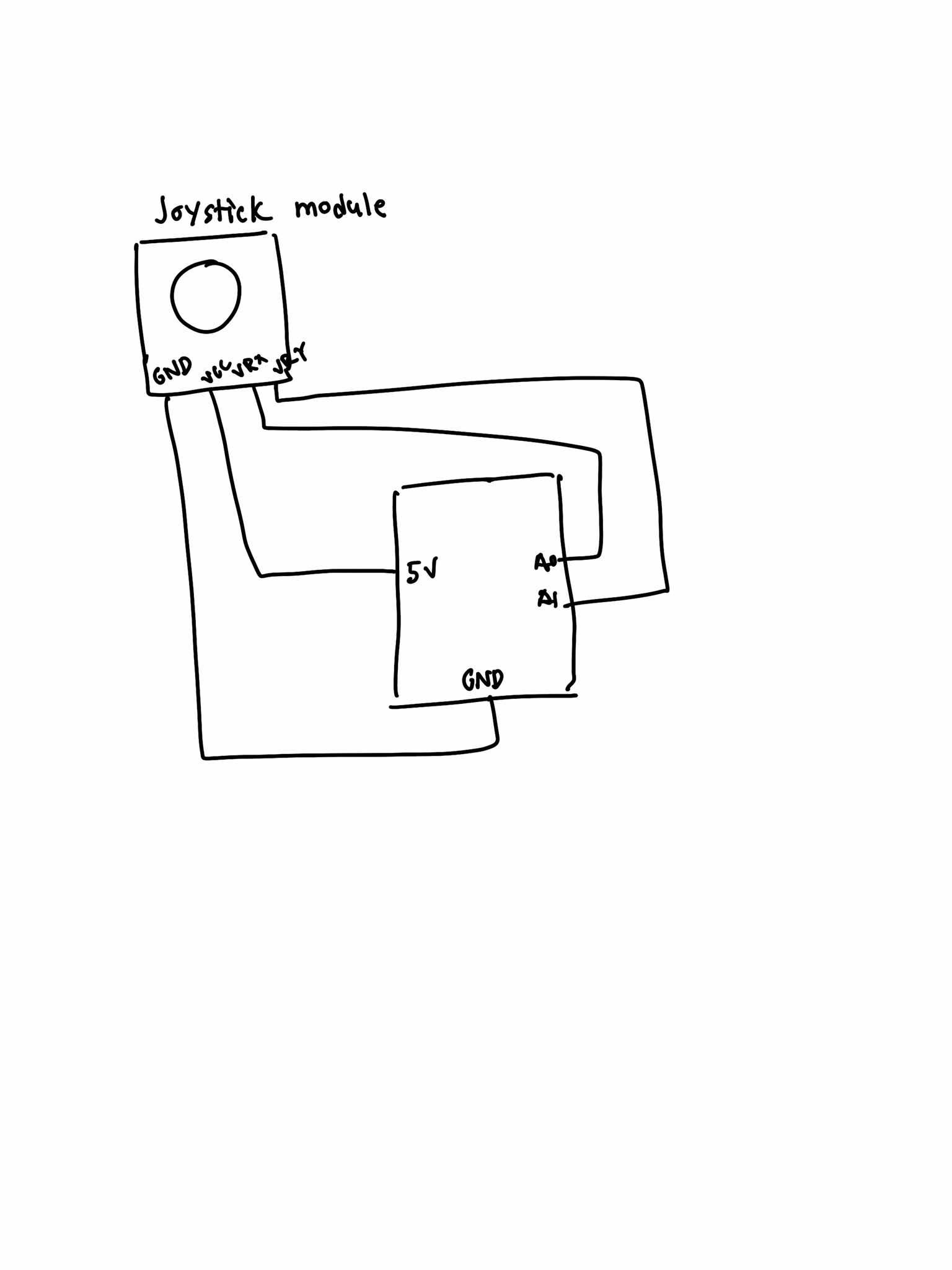
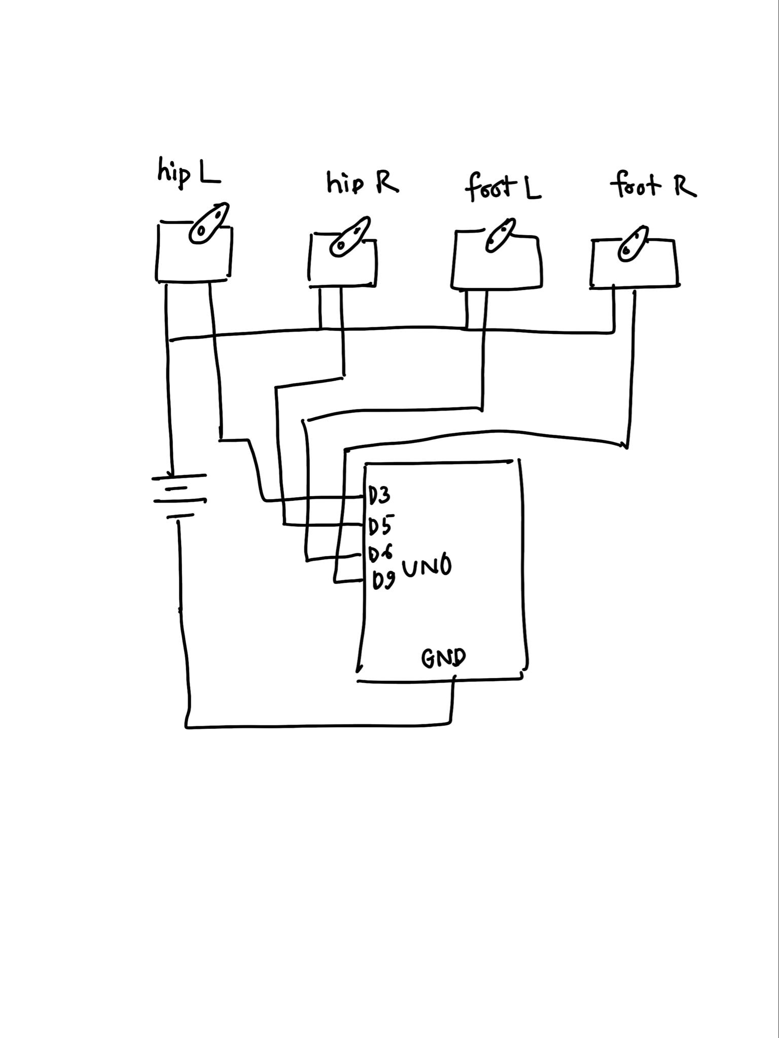
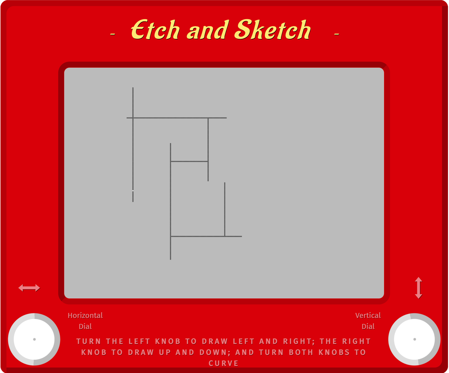
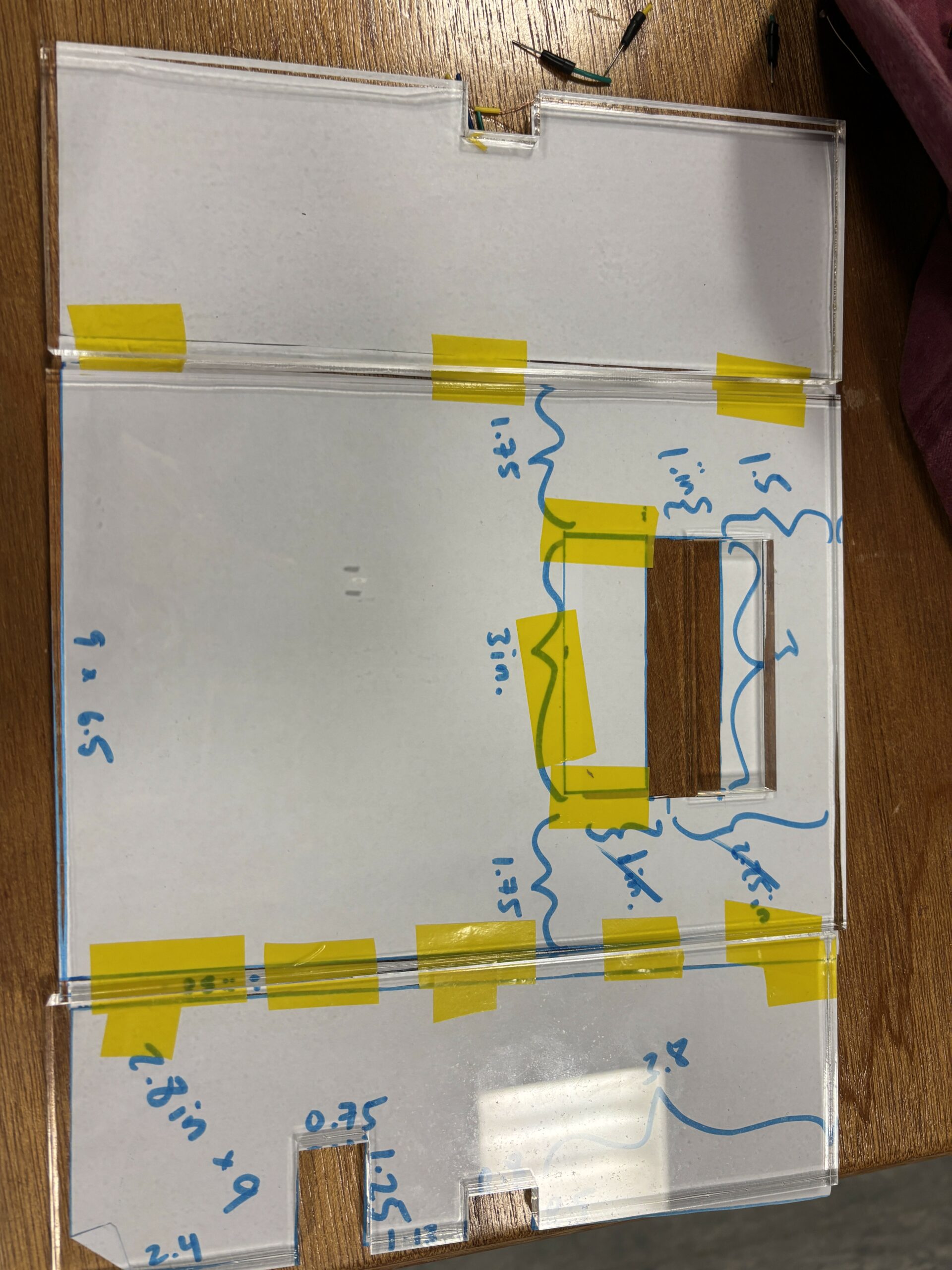
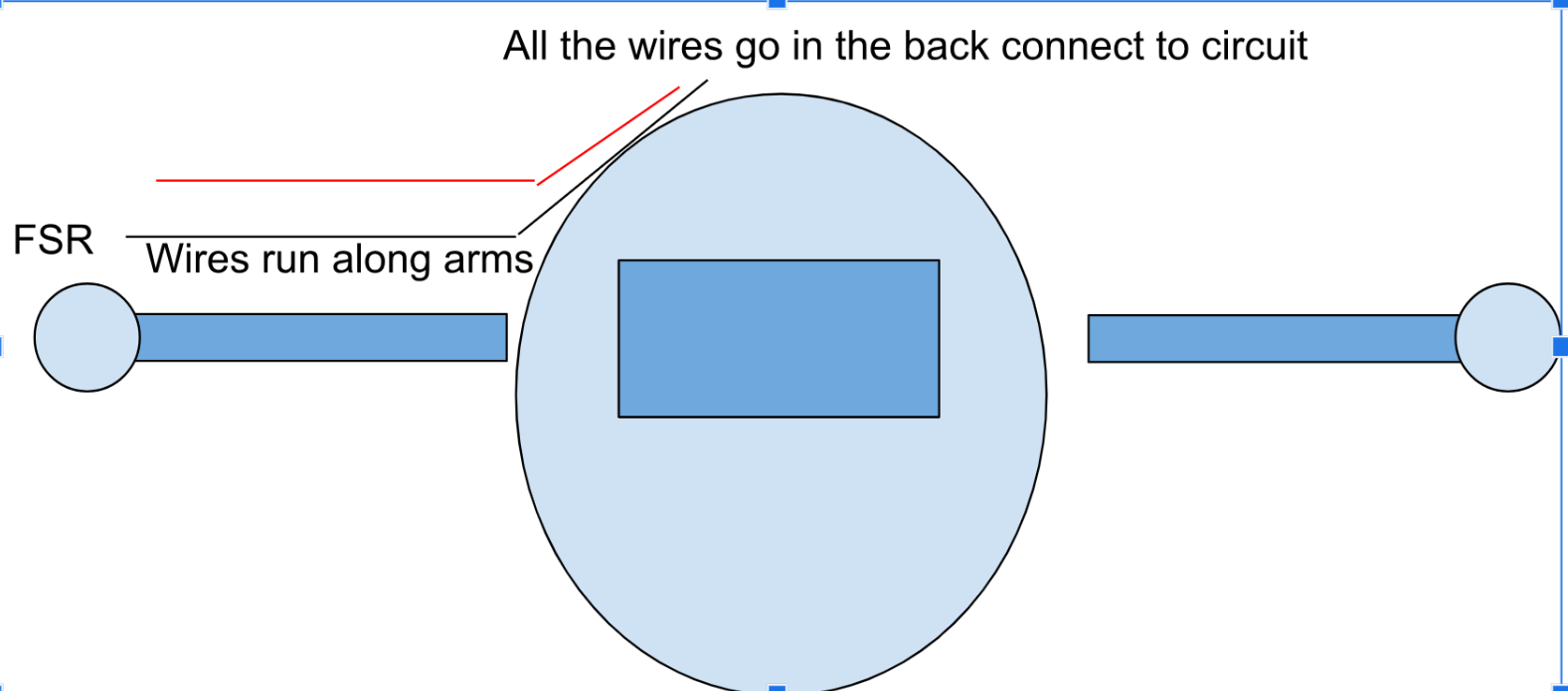
The sketch for the wiring and connections.

Schematic for the Arduino connection and port mapping

For this assignment, potentiometer was used for adjusting the vertical affects of the wind. The FSR – Force Sensitive Resistor was used to move the ball horizontally. Depending on the pressure, you would have rightward movement. For the LED in the middle, that was used to indicate impact with the surface. Hence would light up whenever the ball would bounce. As for the right most LED, it would light up, when the button on P5.JS was triggered, i.e increase the brightness. The port-mapping and pin assignment are visible on both the sketch, as well as the schematic.

P5 project and code:

let fsrVal = 0;
let potVal = 0;

let led1Brightness = 0; 
let bounceFlag = 0;

let position, velocity, acceleration, gravity, wind;
let drag = 0.99;
let mass = 50;
let prevBounce = false;

let button;

function setup() {
  createCanvas(640, 360);
  position = createVector(width / 2, 0);
  velocity = createVector(0, 0);
  acceleration = createVector(0, 0);
  gravity = createVector(0, 0.5 * mass);
  wind = createVector(0, 0);

  button = createButton('Increase Brightness');
  button.position(10, height + 10);
  button.mousePressed(() => {
    led1Brightness = (led1Brightness + 200) % 256;
  });
}

function draw() {
  background(255);

  // ========== Task 1: move ellipse horizontally using FSR only ==========
  let xMapped = map(fsrVal, 0, 1023, 50, width - 50);
  position.x = xMapped;

  // ========== Task 3: adjust gravity based on potentiometer ==========
  let gravityScale = map(potVal, 0, 1023, 0.1, 0.5);
  gravity.y = gravityScale * mass;

  applyForce(wind);
  applyForce(gravity);
  velocity.add(acceleration);
  velocity.mult(drag);
  position.add(velocity);
  acceleration.mult(0);

  ellipse(position.x, position.y, mass, mass);

  // ========== Bounce Logic ==========
  let isBouncing = false;
  if (position.y > height - mass / 2) {
    velocity.y *= -0.9;
    position.y = height - mass / 2;
    isBouncing = true;
  }

  // Detect rising edge (bounce just occurred)
  bounceFlag = isBouncing && !prevBounce ? 1 : 0;
  prevBounce = isBouncing;

  // ========== Serial send ==========
  if (serialActive) {
    let sendToArduino = led1Brightness + "," + bounceFlag + "\n";
    writeSerial(sendToArduino);
  }

  // Debugging values
  fill(0);
  text(`FSR: ${fsrVal}`, 10, 20);
  text(`Pot: ${potVal}`, 10, 40);
  text(`LED Brightness: ${led1Brightness}`, 10, 60);
}

function applyForce(force) {
  let f = p5.Vector.div(force, mass);
  acceleration.add(f);
}

function keyPressed() {
  if (key == " ") {
    setUpSerial();
  }
  
   if (key === 'l' || key === 'L') {
    velocity.y = -10; // Negative Y velocity = upward bounce
  }
}

// Serial reading
function readSerial(data) {
  if (data != null) {
    let fromArduino = split(trim(data), ",");
    if (fromArduino.length === 2) {
      fsrVal = int(fromArduino[0]);
      potVal = int(fromArduino[1]);
    }
  }
}


/*
int fsrPin = A0;        // Task 1 - Move ellipse
int led1Pin = 3;        // Task 2 - LED controlled by p5.js button (PWM)
int potPin = A2;        // Task 3 - Gravity control
int led2Pin = 5;        // Task 3 - Blink on bounce (PWM)

int led1Brightness = 0;
bool bounceFlag = false;

void setup() {
  Serial.begin(9600);
  pinMode(LED_BUILTIN, OUTPUT);
  pinMode(led1Pin, OUTPUT);
  pinMode(led2Pin, OUTPUT);

  // Initial blink
  digitalWrite(led1Pin, HIGH);
  digitalWrite(led2Pin, HIGH);
  delay(200);
  digitalWrite(led1Pin, LOW);
  digitalWrite(led2Pin, LOW);

  while (Serial.available() <= 0) {
    digitalWrite(LED_BUILTIN, HIGH);
    Serial.println("0,0");
    delay(300);
    digitalWrite(LED_BUILTIN, LOW);
    delay(50);
  }
}

void loop() {
  while (Serial.available()) {
    digitalWrite(LED_BUILTIN, HIGH);
    int led1Val = Serial.parseInt();       // brightness from p5.js (0–255)
    int bounce = Serial.parseInt();        // whether ball bounced (1 or 0)
    if (Serial.read() == '\n') {
      analogWrite(led1Pin, led1Val);
      if (bounce == 1) {
        digitalWrite(led2Pin, HIGH);
        delay(50);
        digitalWrite(led2Pin, LOW);
      }

      int fsrVal = analogRead(fsrPin);
      int potVal = analogRead(potPin);
      Serial.print(fsrVal);
      Serial.print(",");
      Serial.println(potVal);
    }
  }
  digitalWrite(LED_BUILTIN, LOW);
}


*/

In addition to code provided by Professor Mang and Sherwood, some implementations were done such as ‘key-press’ function utilizing letter ‘l’ or ‘L’ to make the ball bounce again for the demonstration and as for the port mappings, they have been commented out and labelled inside the code.

Arduino code:

int fsrPin = A0;        // Task 1 - Move ellipse
int led1Pin = 3;        // Task 2 - LED controlled by p5.js button (PWM)
int potPin = A2;        // Task 3 - Gravity control
int led2Pin = 5;        // Task 3 - Blink on bounce (PWM)

int led1Brightness = 0;
bool bounceFlag = false;

void setup() {
  Serial.begin(9600);
  pinMode(LED_BUILTIN, OUTPUT);
  pinMode(led1Pin, OUTPUT);
  pinMode(led2Pin, OUTPUT);

  // Initial blink
  digitalWrite(led1Pin, HIGH);
  digitalWrite(led2Pin, HIGH);
  delay(200);
  digitalWrite(led1Pin, LOW);
  digitalWrite(led2Pin, LOW);

  while (Serial.available() <= 0) {
    digitalWrite(LED_BUILTIN, HIGH);
    Serial.println("0,0");
    delay(300);
    digitalWrite(LED_BUILTIN, LOW);
    delay(50);
  }
}

void loop() {
  while (Serial.available()) {
    digitalWrite(LED_BUILTIN, HIGH);
    int led1Val = Serial.parseInt();       // brightness from p5.js (0–255)
    int bounce = Serial.parseInt();        // whether ball bounced (1 or 0)
    if (Serial.read() == '\n') {
      analogWrite(led1Pin, led1Val);
      if (bounce == 1) {
        digitalWrite(led2Pin, HIGH);
        delay(50);
        digitalWrite(led2Pin, LOW);
      }

      int fsrVal = analogRead(fsrPin);
      int potVal = analogRead(potPin);
      Serial.print(fsrVal);
      Serial.print(",");
      Serial.println(potVal);
    }
  }
  digitalWrite(LED_BUILTIN, LOW);
}

Demo Video:

Video Demo

In the video, the FSR is used to move the ball on the X-axis i.e task 1. The potentiometer value, which is set to zero, is tuned up. When it increases, the vertical wind pressure makes the bounce and rebound lower. Nonetheless, whenever it bounces, the red LED in the middle lights up i.e task 3. Using P5.js, the brightness can be adjusted, which is demonstrated and visualized through the LED on the right-most side.

Challenges:

Since I was in the hospital, couldn’t get to team up with anyone, missed out on the lecture, it was extremely hard to configure and understand the serial communication between P5.js and Arduino. Nonetheless, after going on and on, again and again over Professor Shiloh’s notes, I finally got it to work.

The tutorials online had a software that used node.js for the communication. A misdirection which costed me my time and energy. Took forever to debug. Since my classmates were busy and I had everything piled up, getting it done on time was hard. Nonetheless, managed to do so. As for the other challenges, the LED light for increase in Brightness was initially green. It wouldn’t increase in brightness significantly, which led me to suspect issue with the code. After much time spent, it was realized that that LED despite working, for some-reason didn’t respond to the PWM signals as accurately as the RED one. So, it was swapped with the RED LED.

Preliminary Concept for the final Project

The concept for the final project kept on varying from a robotic soccer leg ( discussed with Professor Aya) to a prosthetic hand, which was discussed in detail with Professor Shiloh. The final project as of now remains unclear. I do want to make something crazy and go all out. Currently I think of something that involves me reusing and crafting from scratch by reusing already available materials (hacking). Hence, something which fits a perfect balance between hardware, and soft-logic. Something that makes use of all of the concepts (or most of them), which were learnt inside the class.


Final Project Documentation

Concept / Description

My project was inspired by simple robots / AI from the 90s and early 2000s (like the Tamagotchi pets) made to just be fun toys for kids. In our current age, we’re so used to advanced AIs that can complete complex thoughts, but I wanted to inspire a sense of nostalgia and comfort from this robot. It also serves as an anchor point to see how far we’ve come in the past 2 decades as more “intelligent” AI develop. The main interaction and premise of this robot are centered around its hunger and feeding it. It starts off neutral, but as you feed the robot, it gets happier. However, if you overfeed it, it’ll get nauseous. If you don’t feed it at all, overtime, it’ll get incredibly sad. You need to watch out for its needs and make sure it’s in this Goldilocks state of happiness and being well-fed. The robot loves attention, so if you hold its hand, it’ll also get happy regardless of its hunger levels. However, if you hold its hand with too much force, it’ll feel pain and get sad.

The music and sounds from the p5 sketch use 8bit audio to tie in the retro feel of the robot. The limited pixels and display from the LCD screen also give a sense of limited technology to take you back a few decades.

Video Demonstration:

Cleaner version: https://drive.google.com/file/d/15zkLTwSH97eqe1FHWSYq188_5F6aHUkX/view?usp=sharing

Messier version:

https://drive.google.com/file/d/1rzX4EbBVYXzRDgda-7Dk08BkqQ0m9Qx8/view?usp=sharing

Media (photos)

Implementation

Link to sketch: https://editor.p5js.org/bobbybobbb/full/yeMCC3H4B

p5 and Arduino are communicating with each other by sending each other values like the emotional state of the robot and FSR values. p5 controls the emotional value (each number represents a different emotion) and sends it to Arduino so that the LCD screen will display the correct facial expression and the LED lights will display the corresponding colors. The emotional state also controls the servo motors that act as the legs. The force sensitive resistor values get sent to p5 to control sadness and happiness since they act as hands being held. Interactions also correspond with specific sounds, which I’m particularly proud of as it adds a lot more atmosphere to the experience. For example, holding hands triggers a specific sound, holding the hands too hard also triggers another sound, feeding the robot triggers another sound, the hunger bar going down triggers a sound, and feeding on a full stomach also triggers a different sound.

Once I had all my functionality implemented like the code and the circuit, I moved on to beautifying the robot by building a casing for it. The wires and circuit make it hard to make a simple box for the robot, so I had to do a lot of paper-prototyping at first to get the shape and dimensions of casing. By using paper, I could easily cut and paste pieces together to fit across the robot. Even if I made mistakes, the adaptability of paper made it simple to fix. Once I found the right dimensions, I created Illustrator files to laser cut pieces of acrylic out. From there, I needed to drill sides together to create a 3-dimensional box shape.

Early prototype:

Video of early prototype (Had to make sure all the functionality worked before the visuals came in):

https://drive.google.com/file/d/1RJzqBWGN9Tan1qQ-CqXS2n1jlQ580AKP/view?usp=sharing

User  Testing

When user testing, peers commented on the user interface of the p5 sketch and mentioned how it’d be nice if the sketch matched the physical body of the robot better.  They also mentioned the awkward holding of the robot (before it was encased). I was at a loss for how to build the casing of the body, and so I asked some of my peers who are more experienced with these kind of things for suggestions. I ended up using the L shaped brackets to help make the box and laser cutting my box out of acrylic under the advice of Sumeed and David, and with the help of IM lab assistants.

Difficulties

Communication between p5 and Arduino was difficult to implement because my computer crashed at some point from the code. I wasn’t sure what I did wrong, so I referred to the example from class, replicated it and changed some values to test out simple functionality at first. Once I made sure Arduino and p5 were communicating in real time, I started building my project from there.

Most of my difficulties came from hardware and building the physical robot since I’m most unfamiliar with hardware compared to software. For example, I wanted the FSR to resemble hands poking out the robot, but upon taping down the FSR, I realized that depending on where you tape the FSR, this’ll affect the sensor readings. There’s also very limited room on the base plate I’m using to hold the Arduino and breadboard for all the wiring involved. For example, I wanted everything to be contained in a neat box, but the Neopixel wires stick out quite a bit. I ended up just making a bigger box to counteract this.

Using Neopixels was a huge part of my project and a must. To use them, I needed to solder wires to the Neopixels, which took a really long time because instead of soldering into a hole, I’m soldering to a flat surface and have to make sure the wires stick on to that flat copper surface. Sometimes, the wires would fall off or it’d just be really difficult to get the wire to stick to the solder on the copper surface. After soldering came the software; I tested using the example strandtest by Adafruit, but it didn’t have the correct outcome even though the lights turned on perfectly. They weren’t displaying the right colors. Mind you, I randomly took these from the IM lab, so I had no idea what type of Neopixels they were. It simply came down to testing out different settings for the different types of Neopixels that exist until I hit the right one.

The LCD screen is also technically upside-down on the robot body because it’s the only way for maximum room on the breadboard to put wires in. Since I had no other option but to put the screen upside down, I had to draw and display all the pixels and bytes upside down. This required a lot of coordination and rewiring my brain’s perspective.

Future Improvements

In the future, I want to use an alternate source of power for the servo motors and Neopixels because every time the servo motors run, the LCD screen blinks and is less bright because the motors take up a lot of power. Every time the Neopixels switch from one color to another, the LCD screen is also affected. I think hooking up a battery to the circuit would solve this problem. In the future, I think more sensors and ways to interact with the robot would also be nice.

Progress Report

Current Progress

The p5.js environment has been successfully designed, I went from a 2D version to a 3D avatar rendered in WEBGL. The system also includes a custom font and a wooden background platform for visual warmth. A floating instruction frame appears at the beginning of the interaction, prompting users to “press to start.”

The Arduino hardware components (photoresistor, DIY capacitive touch sensor, LEDs, and buzzer) are currently in the process of being tested. I am actively working on matching sensor input with the avatar’s behavior (e.g., face expression, sound).

Video 

What’s Being Tested

    • Touch Sensor + LEDs → Plant’s mood environment (happy, sad)

    • Touch Input → Start and Display instructions

    • Avatar Design → Body, leaf animation, emotional face drawn in p5.js

    • Instructions Interface → Initial user onboarding screen

 Pending Tasks

    • Finalizing the integration of the Arduino circuit into the physical plant (soldering and arranging).

    • Smoothing the interaction between sensor readings and p5.js visual/audio feedback.

    • Conducting user tests to assess how people engage with the plant-avatar system.

      Avatar Demo

Week 13 – User Testing

Generally, my testing went okay, though because I had not given instructions I think, though, my design was pretty intuitive in such. way I think they got what they were supposed to do. Because my project had to do with modulating sound, the feedback is pretty instantaneous, and because there was not objective, really, users could just mess around with what you can do and really quickly get the hang of it. I am still working on adding an instructions screen on p5, though. I think an easy instructions page would provide all the information people will need to do with my project, just explaining what the different controllers on my cat thing do to the sound.

IMG_8595