For my final project, I created a hybrid digital-physical escape room-style game inspired by timed bomb defusal sequences in video games. The entire experience blends physical interactivity through Arduino with dynamic visuals and logic in p5.js. The result is a tense, fast-paced game where players must race against the clock to complete four distinct challenges and successfully input a final disarm code before the device “explodes.”
The core idea was to simulate a bomb defusal setup using varied mini-games—each one testing a different skill: speed, logic, memory, and pattern recognition.

How the Game Works
The digital game runs in p5.js and connects to a single Arduino board that handles inputs from physical buttons, rotary encoders, and switches. Players are given 80 seconds to complete four escalating stages:
-
Button Mash Challenge – Tap a physical button repeatedly until a counter hits the target.
-
Math Riddle Quiz – Use a button to select answers and confirm; one wrong answer ends the game.
-
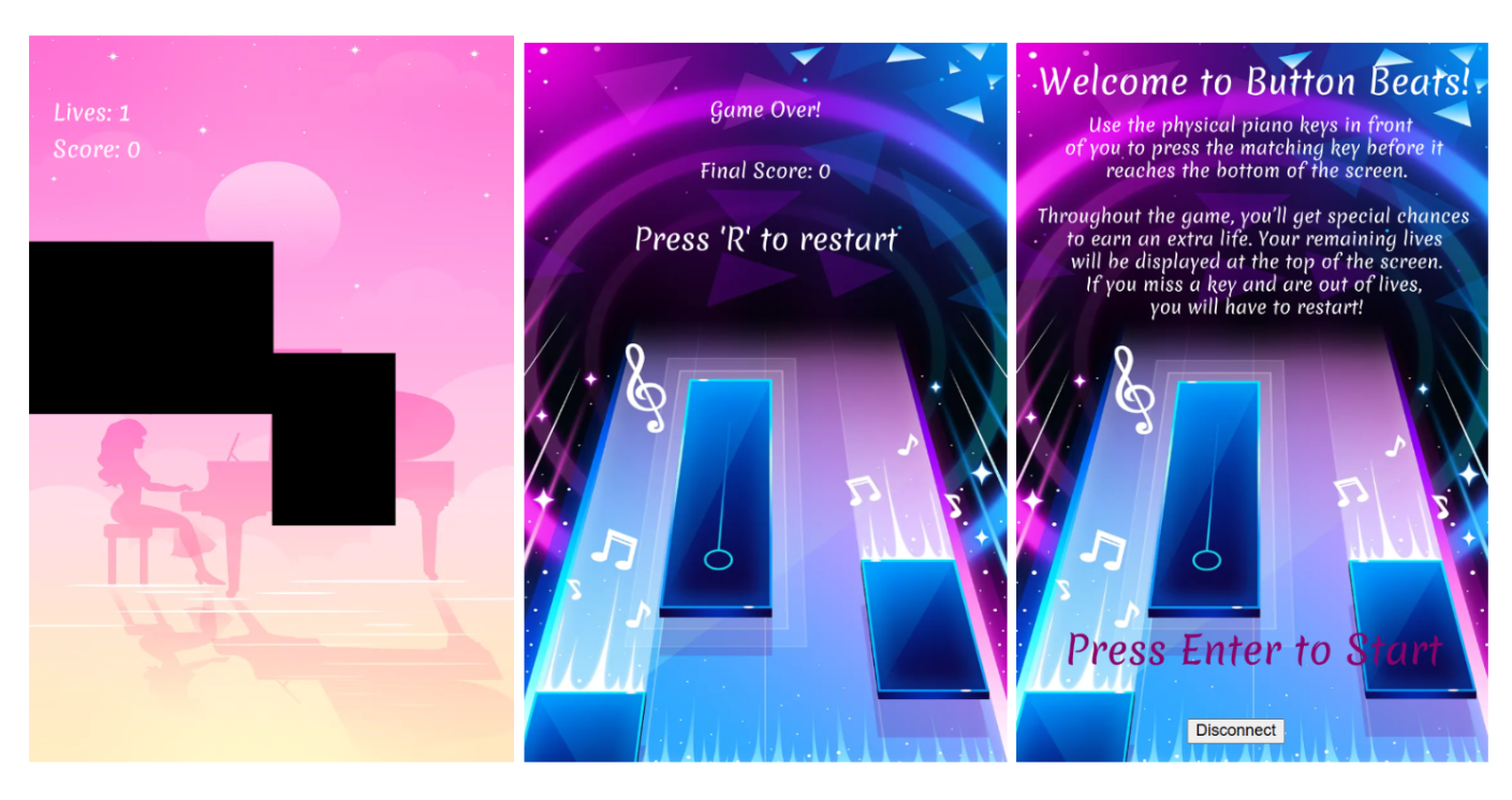
Note Match – Listen to a played note and match it using one of four physical options.
-
Morse Code Challenge – Decode a flashing Morse signal and reproduce it using a button.
After all four stages, the player must recall and enter a 4-digit code, derived from the hidden logic behind each stage. If they enter it correctly, the bomb is defused and a green screen confirms success. Otherwise—boom. Game over.
A countdown timer runs persistently, and sound effects, animations, and images change based on player progress, creating an immersive narrative.
Video Demo: https://drive.google.com/drive/folders/1xghtShbdS5ApygD3-LrT41DRQsbnQ98U?usp=share_link
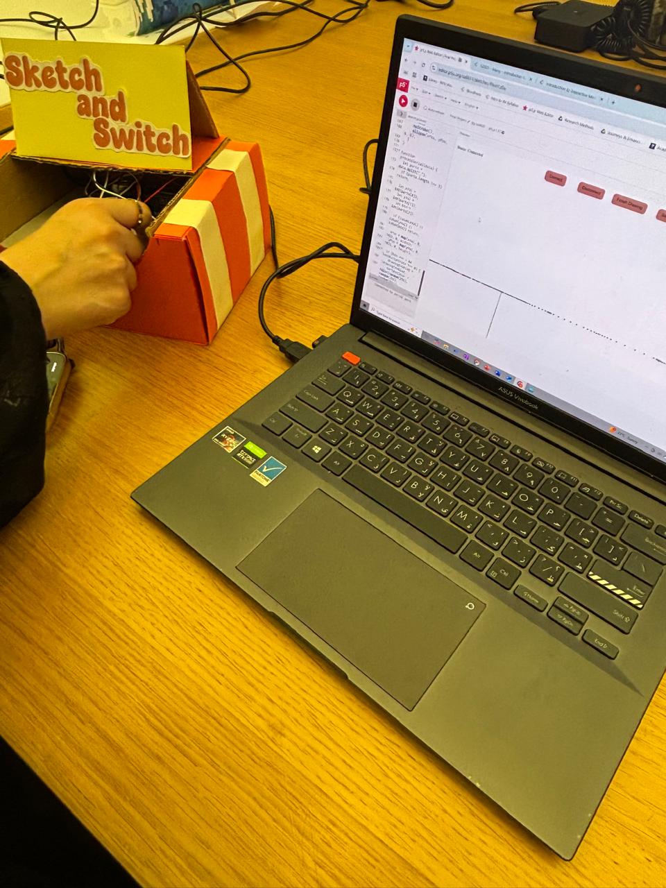
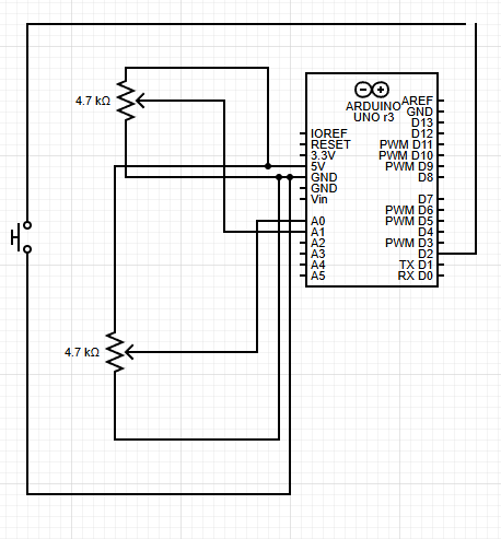
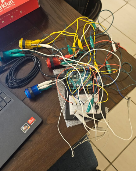
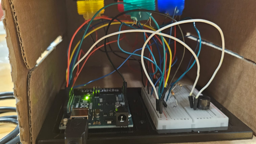
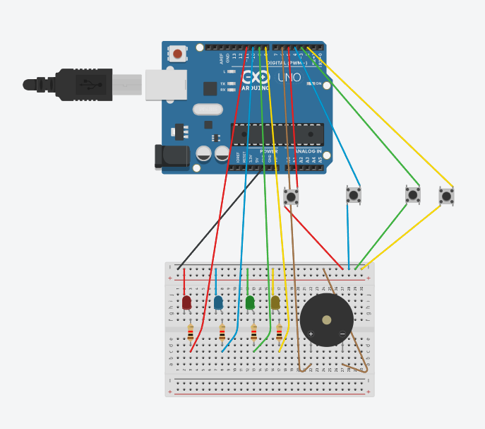
Hardware & Physical Build
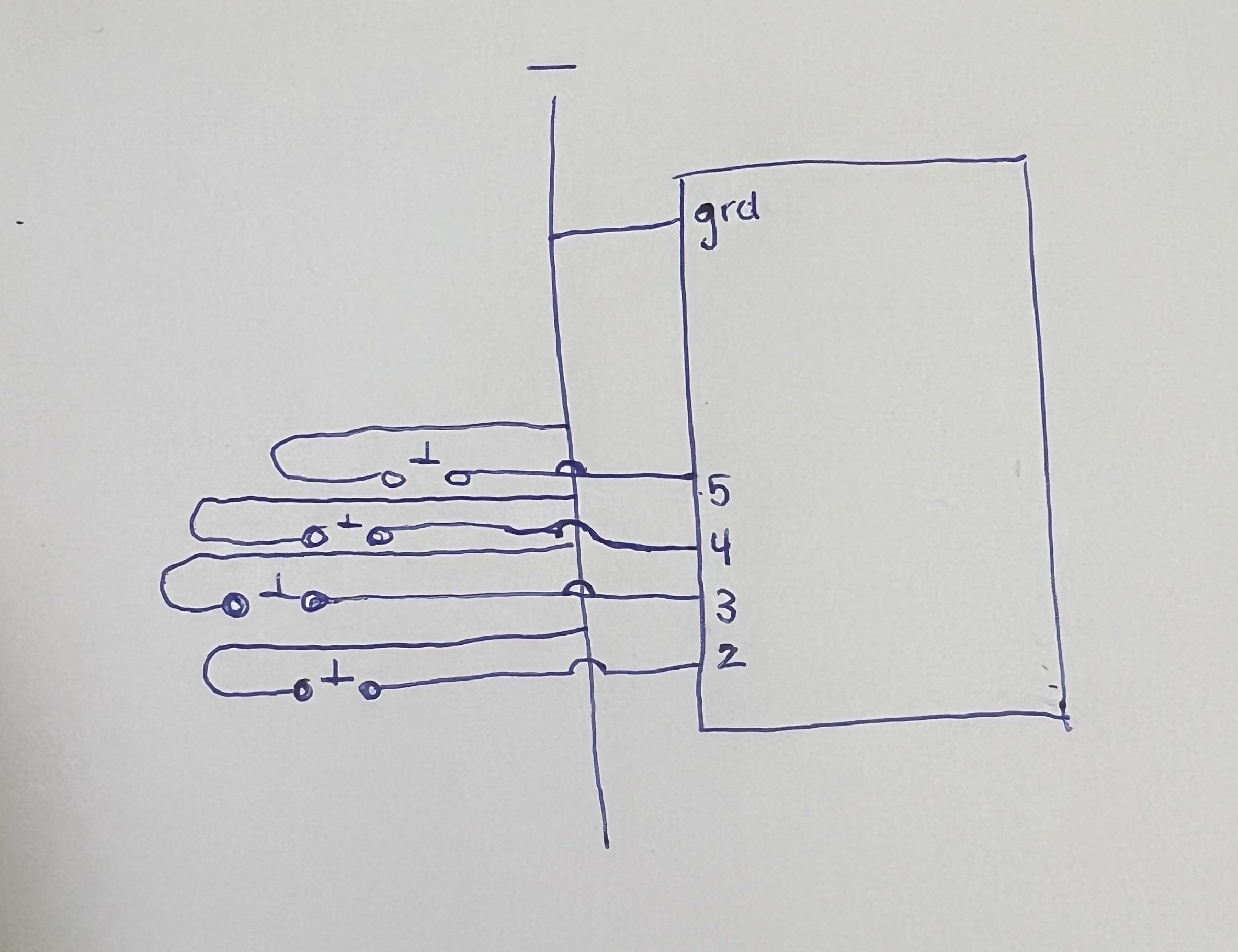
This game relies heavily on Arduino to provide tactile interaction. Here’s how each component contributes:
-
Button Mash: A simple digital input wired to a button switch.
-
Math Quiz: A designated button allows users to scroll through numeric answers, with a button to lock in their choice.
-
Note Match: A speaker plays a pitch generated from Arduino, and players must select the correct note using four distinct buttons.
-
Morse Code: The p5 screen shows a pattern, which the player must replicate with button presses (dots and dashes).
To enhance the look, I created screen graphics for each stage and embedded them as assets into the p5.js sketch. I also used audio cues (success/failure sounds) to give it more feedback.
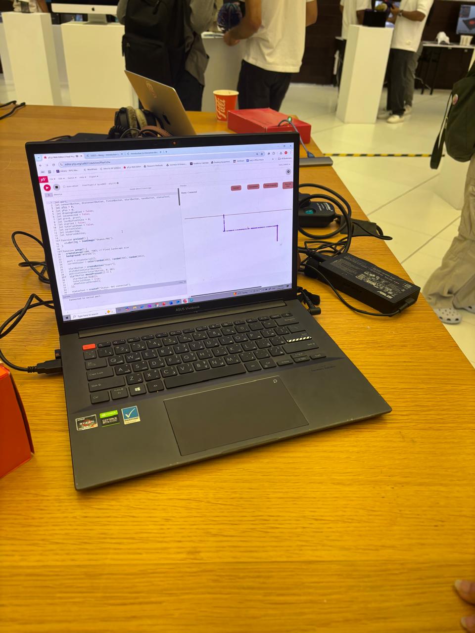
Code + Serial Integration
The p5.js sketch acts as the game engine and controller, managing state transitions, timing, visuals, and logic. Arduino handles all the physical input and sends data to p5.js over serial using a consistent message format.
Initially, I experimented with sending raw characters for stage signals and player responses, but ran into reliability issues. Eventually, I switched to using numeric values and simple prefixes which made parsing much more predictable.
There’s a small but critical serial timing issue to manage — making sure Arduino doesn’t flood the buffer, and that p5 reads and trims data consistently. I handled this using readUntil("\n").trim() on the p5 side and line breaks on the Arduino side.
I also implemented a game reset trigger — pressing “R” after the game ends resets both the p5 and Arduino states and lets the player start over without refreshing the browser.
Arduino Code:
// initialize connections
const int BUTTON_PINS[] = {2, 3, 4, 5};
const int BUZZER_PIN = 8;
const int CONFIRM_PIN = 7;
const int POT_PIN = A0;
const int RED_LED_PIN_1 = 9;
const int YELLOW_LED_PIN_1 = 10;
const int GREEN_LED_PIN_1 = 12;
const int RED_LED_PIN_2 = 13;
const int YELLOW_LED_PIN_2 = 11;
const int GREEN_LED_PIN_2 = 6;

// initialize all game variables
int currentPressed = -1;
int targetNote = -1;
bool newRound = true;
bool morsePressed = false;
unsigned long morseStart = 0;
int buttonMashCount = 0;
int currentGame = 0;

bool bombDefused = false;
bool bombExploded = false;
bool gameEnded = false;

unsigned long gameStartTime;
const unsigned long GAME_DURATION = 80000;

bool inCountdown = false;
unsigned long lastBeepTime = 0;
unsigned long beepInterval = 1000;

int blinkState = 0;
unsigned long lastBlinkTime = 0;
unsigned long blinkInterval = 400;
bool ledOn = false;

void setup() {
  Serial.begin(9600);
  while (!Serial);
  // setup and initialize all physical connections
  for (int i = 0; i < 4; i++) pinMode(BUTTON_PINS[i], INPUT_PULLUP);
  pinMode(BUZZER_PIN, OUTPUT);
  pinMode(CONFIRM_PIN, INPUT_PULLUP);
  pinMode(POT_PIN, INPUT);
  pinMode(RED_LED_PIN_1, OUTPUT);
  pinMode(YELLOW_LED_PIN_1, OUTPUT);
  pinMode(GREEN_LED_PIN_1, OUTPUT);
  pinMode(RED_LED_PIN_2, OUTPUT);
  pinMode(YELLOW_LED_PIN_2, OUTPUT);
  pinMode(GREEN_LED_PIN_2, OUTPUT);

  randomSeed(analogRead(A1));
  gameStartTime = millis();
}

void loop() {
  if (Serial.available()) {
    String input = Serial.readStringUntil('\n');
    input.trim();

    if (input == "RESET") {
      resetGame(); // reset game variables when reset command is received
      return;
    }
    // to identify target note sent by arduino
    if (input.startsWith("NOTE:")) {
      targetNote = input.substring(5).toInt();  // parses 6th character which holds numeric value
      newRound = true;
      return;
    }
    // if bomb is defused on p5, it sends input to arduino and bomb is defused here as well
    if (input == "DEFUSED"){
      bombDefused= true;
      gameEnded = true;
      return;
    }
    // in case user makes a mistake in games, p5 sends exploded to arduino
    if (input == "EXPLODED") {
      bombExploded = true;
      gameEnded = true;
      Serial.println("EXPLOSION_ACK");
      return;
    }
    // to parse game sent to arduino each time a challenge is completed and we move to next one
    currentGame = input.toInt();

    if (currentGame == 0) buttonMashCount = 0;
    if (currentGame == 2) newRound = true;
  }
  // when bomb is defused or explodes
  if (gameEnded) {
    noTone(BUZZER_PIN);
    return;
  }
  // turn of all leds
  if (bombExploded || bombDefused) {
    digitalWrite(RED_LED_PIN_1, LOW);
    digitalWrite(YELLOW_LED_PIN_1, LOW);
    digitalWrite(GREEN_LED_PIN_1, LOW);
    digitalWrite(RED_LED_PIN_2, LOW);
    digitalWrite(YELLOW_LED_PIN_2, LOW);
    digitalWrite(GREEN_LED_PIN_2, LOW);

    noTone(BUZZER_PIN);
  }

  unsigned long elapsed = millis() - gameStartTime;
  // handles blinking of leds alternatively until 30 seconds are left
  unsigned long remaining = GAME_DURATION - elapsed;
  if (!gameEnded && !bombDefused) {
  if (remaining > 30000) {
    if (millis() - lastBlinkTime >= 400) {
      lastBlinkTime = millis();
      ledOn = !ledOn;

      digitalWrite(RED_LED_PIN_1, LOW);
      digitalWrite(YELLOW_LED_PIN_1, LOW);
      digitalWrite(GREEN_LED_PIN_1, LOW);
      digitalWrite(RED_LED_PIN_2, LOW);
      digitalWrite(YELLOW_LED_PIN_2, LOW);
      digitalWrite(GREEN_LED_PIN_2, LOW);


      if (ledOn) {
        if (blinkState == 0) {
          digitalWrite(GREEN_LED_PIN_1, HIGH);
          digitalWrite(GREEN_LED_PIN_2, HIGH);}
        else if (blinkState == 1) {
          digitalWrite(YELLOW_LED_PIN_1, HIGH);
          digitalWrite(YELLOW_LED_PIN_2, HIGH);}
        else if (blinkState == 2) {
          digitalWrite(RED_LED_PIN_1, HIGH);
          digitalWrite(RED_LED_PIN_2, HIGH);}

        blinkState = (blinkState + 1) % 3;
      }
    }
  }
  // last 30 seconds yellow starts blibking with beeps
  else if (remaining > 13000) {
    if (millis() - lastBlinkTime >= 500) {
      lastBlinkTime = millis();
      ledOn = !ledOn;

      //ensure other LEDs are off
      digitalWrite(RED_LED_PIN_1, LOW);
      digitalWrite(RED_LED_PIN_2, LOW);
      digitalWrite(GREEN_LED_PIN_1, LOW);
      digitalWrite(GREEN_LED_PIN_2, LOW);

      // Yellow blinking
      digitalWrite(YELLOW_LED_PIN_1, ledOn ? HIGH : LOW);
      digitalWrite(YELLOW_LED_PIN_2, ledOn ? HIGH : LOW);
    }
    // beeps
    if (millis() - lastBeepTime >= 1000) {
      lastBeepTime = millis();
      tone(BUZZER_PIN, 1000, 100);
    }
  }
  // last 10 seconds red is blinking with faster beeps
  else if (remaining > 3000) {
    if (millis() - lastBlinkTime >= 300) {
      lastBlinkTime = millis();
      ledOn = !ledOn;
      digitalWrite(RED_LED_PIN_1, ledOn ? HIGH : LOW);
      digitalWrite(RED_LED_PIN_2, ledOn ? HIGH : LOW);
    }

    if (millis() - lastBeepTime >= 500) {
      lastBeepTime = millis();
      tone(BUZZER_PIN, 1200, 100);
    }
  }
}
  // bomb exploded cause time is up
  if (elapsed >= GAME_DURATION && !bombDefused) {
    bombExploded = true;
    gameEnded = true;
    Serial.println("EXPLODED");
    return;
  }
  // Serial input


  switch (currentGame) {
    case 0: handleButtonMash(); break;
    case 1: handleMathQuiz(); break;
    case 2: handleNoteMatch(); break;
    case 3: handleMorseCode(); break;
  }
}
// to handle physicak input for each game
void handleButtonMash() {
  static unsigned long lastPressTime = 0;
  static bool lastButtonState = HIGH;
  bool currentState = digitalRead(CONFIRM_PIN);
  // each press sends 1 to p5, which increments counter for current presses
  if (lastButtonState == HIGH && currentState == LOW && millis() - lastPressTime > 200) {
    buttonMashCount++;
    lastPressTime = millis();
    Serial.println("1");
  }
  lastButtonState = currentState;
}
// resetGame function defined to reset all game variables and start game again
void resetGame() {
  bombDefused = false;
  bombExploded = false;
  gameEnded = false;
  buttonMashCount = 0;
  currentPressed = -1;
  currentGame = 0;
  newRound = true;
  morsePressed = false;
  targetNote = -1;
  morseStart = 0;
  gameStartTime = millis();
  ledOn = false;
  blinkState = 0;
  lastBlinkTime = 0;
  lastBeepTime = 0;

  // turn off all LEDs and buzzer
  digitalWrite(RED_LED_PIN_1, LOW);
  digitalWrite(YELLOW_LED_PIN_1, LOW);
  digitalWrite(GREEN_LED_PIN_1, LOW);
  digitalWrite(RED_LED_PIN_2, LOW);
  digitalWrite(YELLOW_LED_PIN_2, LOW);
  digitalWrite(GREEN_LED_PIN_2, LOW);
  noTone(BUZZER_PIN);
}

void handleMathQuiz() {
  static int selectedNum = 0;
  static int lastButtonState = HIGH;
  static unsigned long lastDebounceTime = 0;
  const unsigned long debounceDelay = 200;

  int currentState = digitalRead(BUTTON_PINS[0]); // increment button on pin 2

  // handle incrementing selected number
  if (lastButtonState == HIGH && currentState == LOW && (millis() - lastDebounceTime > debounceDelay)) {
    selectedNum = (selectedNum + 1) % 10;
    Serial.print("SELECT:");
    Serial.println(selectedNum);
    lastDebounceTime = millis();
  }
  lastButtonState = currentState;

  // handle confirmation
  if (digitalRead(CONFIRM_PIN) == LOW) {
    delay(50);
    // sends selected number to arduino when confirm button is pressed
    if (digitalRead(CONFIRM_PIN) == LOW) {
      Serial.print("PRESS:");
      Serial.println(selectedNum);
      delay(300);
    }
  }
}

void handleNoteMatch() {
  static unsigned long toneEndTime = 0;
  static bool isPlayingTarget = false;

  // handle new round target note
  if (newRound) {
    noTone(BUZZER_PIN);
    delay(5);
    digitalWrite(BUZZER_PIN, LOW);
    // plays target note sent by p5
    tone(BUZZER_PIN, getPitch(targetNote), 500);
    toneEndTime = millis() + 500;
    isPlayingTarget = true;
    newRound = false;
    return;
  }

  // handle tone playing completion
  if (isPlayingTarget && millis() > toneEndTime) {
    noTone(BUZZER_PIN);
    isPlayingTarget = false;
  }

  // playing note corresponding to button presses
  if (!isPlayingTarget) {
    bool anyPressed = false;
    for (int i = 0; i < 4; i++) {
      if (digitalRead(BUTTON_PINS[i]) == LOW) {
        anyPressed = true;
        if (currentPressed != i) {
          noTone(BUZZER_PIN);
          delay(5);
          currentPressed = i;
          tone(BUZZER_PIN, getPitch(i));
          Serial.println(i);
        }
        break;
      }
    }
    // no note should play when button is not pressed
    if (!anyPressed && currentPressed != -1) {
      noTone(BUZZER_PIN);
      currentPressed = -1;
    }
    // send final answer confirmation when button is pressed
    if (digitalRead(CONFIRM_PIN) == LOW) {
      noTone(BUZZER_PIN);
      Serial.println("CONFIRM");
      delay(300);
      newRound = true;
    }
  }
}

void handleMorseCode() {
  static unsigned long lastDebounceTime = 0;
  const unsigned long debounceDelay = 50; // ms

  int btn = digitalRead(BUTTON_PINS[0]);  // button on pin 2 is used for sending data

  // Button press detection with debouncing
  if (btn == LOW && !morsePressed && (millis() - lastDebounceTime) > debounceDelay) {
    morseStart = millis();
    morsePressed = true;
    lastDebounceTime = millis();
  }

  // Button release detection
  if (btn == HIGH && morsePressed) {
    unsigned long duration = millis() - morseStart;
    morsePressed = false;

    // short press sends . and long press sends -
    if (duration >= 20) {
      Serial.println(duration < 500 ? "." : "-");
    }
    lastDebounceTime = millis();
    delay(100);
  }

  // pressing confirm button sends confirm to p5 which then checks if string formed by user matches morse code proivded
  if (digitalRead(CONFIRM_PIN) == LOW) {
    delay(50); // Debounce
    if (digitalRead(CONFIRM_PIN) == LOW) {
      Serial.println("CONFIRM");
      while(digitalRead(CONFIRM_PIN) == LOW);
      delay(300);
    }
  }
}
// 4 notes chosen for note match
int getPitch(int index) {
  int pitches[] = {262, 294, 330, 349};
  return pitches[index];
}
p5js code:
let port;
let connectBtn;
let startBtn;
let baudrate = 9600;
// initiate all flags required
let showWelcome = true;
let showInstructions = false;
let gameStarted = false;
let currentGame = 0;
let gameCompleted = [false, false, false, false];
let codeDigits = [];
let userCodeInput = "";
let correctCode = "";
let bombDefused = false;
let bombExploded = false;
let stageCompleted = false;
let stageCompleteTime = 0;
let stageDigit = -1;
let imgWelcome, imgInstructions, imgButtonSmash, buttonMashSuccessImg, mathQuizSuccessImg, noteMatchSuccessImg, morseCodeSuccessImg, imgMathRiddle, imgNoteMatch, imgMorseCode1,imgMorseCode2, imgBombDefused, imgBombExploded,imgCodeEntry;
let bombSound;
let playedExplosionSound = false;
let successSound;
let playedSuccessSound = false;
// initiate all game variables
let totalTime = 80;
let startTime;
let pressCount = 0;
let targetPresses = 30;
let challengeActive = false;
let selectedNumber = 0;
let correctAnswer = 5;
let mathAnswered = false;
let feedback = "";
let currentSelection = -1;
let lockedIn = false;
let noteMessage = "";
let noteAnswerIndex = 0;
let morseCode = "";
let userInput = "";
let roundActive = false;
let showSuccess = false;
let showFailure = false;
function preload() {
imgWelcome = loadImage("start.png");
imgInstructions = loadImage("instructions.png");
imgButtonSmash = loadImage("button_smash.png");
buttonMashSuccessImg = loadImage("stage1_success.png");
mathQuizSuccessImg = loadImage("stage2_success.png");
noteMatchSuccessImg = loadImage("stage3_success.png");
morseCodeSuccessImg = loadImage("stage4_success.png");
imgMathRiddle = loadImage("math_riddle.png");
imgNoteMatch = loadImage("note_match.png");
imgMorseCode1 = loadImage("morse_code1.png");
imgMorseCode2 = loadImage("morse_code2.png");
imgBombDefused = loadImage("defused.png");
imgBombExploded = loadImage("exploded.png");
bombSound = loadSound('bomb.mp3');
successSound = loadSound('success.mp3');
imgCodeEntry = loadImage("code_entry.png")
}
function setup() {
createCanvas(600, 600);
textAlign(CENTER, CENTER);
port = createSerial();
}
function startGame() {
startTime = millis(); // Set the start time for the timer
gameStarted = true; // Set the flag to start the game
currentGame = 0; // Set the current game to 0
sendGameSwitch(0); // Send game switch signal to Arduino
startButtonMashChallenge(); // Start the Button Mash Challenge
}
function draw() {
background(220);
// displays screen for when bomb is defused along with sound effects
if (bombDefused) {
image(imgBombDefused, 0, 0, width, height);
if (!playedSuccessSound) {
successSound.play();
playedSuccessSound = true;
}
return;
}
// displays screen for when bomb is exploded along with sound effects
if (bombExploded) {
image(imgBombExploded, 0, 0, width, height);
if (!playedExplosionSound) {
bombSound.play();
playedExplosionSound = true;
}
return;
}
// Welcome Screen display
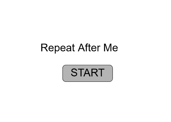
if (showWelcome) {
image(imgWelcome, 0, 0, width, height);
return;
}
//Instructions Screen display
if (showInstructions) {
image(imgInstructions, 0, 0, width, height);
return;
}
// calculates time to keep track of explosion and so on
let elapsed = int((millis() - startTime) / 1000);
let remaining = max(0, totalTime - elapsed);
// if time runs out bomb is exploded
if (remaining <= 0 && !bombDefused) {
bombExploded = true;
return;
}
// handle all incoming data by reading and sending to function after trimming
if (port.opened() && port.available() > 0) {
let data = port.readUntil("\n").trim();
if (data.length > 0) {
handleSerialData(data);
}
}
// toggles success screens for all games
if (stageCompleted) {
switch (currentGame) {
case 0:
// Show success screen for Button Mash
image(buttonMashSuccessImg, 0, 0, width, height);
break;
case 1:
// Show success screen for Math Quiz
image(mathQuizSuccessImg, 0, 0, width, height);
break;
case 2:
// Show success screen for Note Match
image(noteMatchSuccessImg, 0, 0, width, height);
break;
case 3:
// Show success screen for Morse Code
image(morseCodeSuccessImg, 0, 0, width, height);
break;
}
// removes success screen afte 3 seconds and moves onto next game
if (millis() - stageCompleteTime > 3000) {
codeDigits.push(stageDigit);
currentGame++;
sendGameSwitch(currentGame);
stageCompleted = false;
// start the next game
switch (currentGame) {
case 1: startMathQuiz(); break;
case 2: startNoteMatchChallenge(); break;
case 3: startMorseCodeChallenge(); break;
case 4: correctCode = "4297"; break;
}
}
return;
}
// display game screens using functions defined
switch (currentGame) {
case 0: drawButtonMashChallenge(); break;
case 1: drawMathQuiz(); break;
case 2: drawNoteMatchChallenge(); break;
case 3: drawMorseCodeChallenge(); break;
case 4:
correctCode = "4297";
if (userCodeInput === "") startCodeEntry();
drawCodeEntry();
break;
}
// timer display at top of screen
if (gameStarted && !bombDefused && !bombExploded) {
textSize(20);
fill(0);
textAlign(CENTER, TOP);
text("Time Remaining: " + remaining + "s", width / 2, 20);
}
}
function handleSerialData(data) {
if (bombDefused) {
return; // no data should be handled if bomb has been defused
}
// stop handing data once bomb explodes
if (data === "EXPLODED") {
bombExploded = true;
if (port.opened()) {
port.write("EXPLODED\n");
}
return;
}
switch (currentGame) {
case 0:
if (data === "1" && challengeActive) {
pressCount++;
// checks success condition, when user presses button 30 times
if (pressCount >= targetPresses) {
challengeActive = false;
// handle necessary flags for this stage and keep track of time for success screen display
stageDigit = 4;
gameCompleted[0] = true;
stageCompleted = true;
stageCompleteTime = millis();
}
}
break;
case 1:
if (data.startsWith("SELECT:")) {// parses data for this specific game
selectedAnswer = int(data.substring(7)); // 8th character gives actual numeric value
} else if (data.startsWith("PRESS:")) { // for confirm button press
let val = int(data.substring(6)); // 7th character gives digit confirmed by user
// success condition
if (val === correctAnswer) {
feedback = "CORRECT";
stageDigit = 2;
gameCompleted[1] = true;
stageCompleted = true;
stageCompleteTime = millis();
} else {
// in case of wrong answer
bombExploded = true;
if (port.opened()) {
port.write("EXPLODED\n");
}
}
}
break;
// handling data for note match game
case 2:
// if user presses confirm button, checks answer
if (!lockedIn) {
if (data === "CONFIRM") {
lockedIn = true;
// if correct answer is selected
if (currentSelection === noteAnswerIndex) {
noteMessage = "Correct!";
stageDigit = 9;
gameCompleted[2] = true;
stageCompleted = true;
stageCompleteTime = millis();
// if user makes a mistake, they lose
} else {
bombExploded = true;
if (port.opened()) {
port.write("EXPLODED\n");
}
}
} else if (!isNaN(int(data))) {
currentSelection = int(data); // reading data for option selected
}
}
break;
// parsing user input based on arduino feedback to concatenate morse code and compare with original string
case 3:
if (data === "." || data === "-") {
userInput += data;
// if user confirms answer
} else if (data === "CONFIRM") {
if (userInput === morseCode) {
showSuccess = true;
stageDigit = 7;
gameCompleted[3] = true;
stageCompleted = true;
stageCompleteTime = millis();
roundActive = false;
// in case of incorrect answer
} else {
bombExploded = true;
if (port.opened()) {
port.write("EXPLODED\n");
}
} // displays morse code for 5 seconds for user to memorize then disappears
setTimeout(() => {
showSuccess = false;
showFailure = false;
userInput = "";
}, 5000);
}
break;
case 4:
// handles code entry
if (data === "CONFIRM") {
if (userCodeInput.length !== 4) return; // Ignore if code is incomplete
if (userCodeInput === "4297") {
bombDefused = true;
} else {
bombExploded = true;
if (port.opened()) {
port.write("EXPLODED\n");
}
}
}
break;
}
}
// to tell arduino to switch to game being sent
function sendGameSwitch(gameNum) {
if (port.opened()) {
port.write(gameNum + "\n");
}
}
// all game display functions
function startButtonMashChallenge() {
pressCount = 0;
challengeActive = true;
}
function drawButtonMashChallenge() {
image(imgButtonSmash, 0, 0, width, height);
fill(255);
textSize(44);
textAlign(CENTER, CENTER);
text(pressCount, 300,325);
}
function startMathQuiz() {
feedback = "";
correctAnswer = 5;
selectedAnswer = 0;
}
function drawMathQuiz() {
image(imgMathRiddle, 0, 0, width, height);
fill(29,148,94);
rect(width / 2 - 40, 350, 80, 80);
fill(0);
textSize(48);
text(selectedAnswer, width / 2, 370);
}
function startNoteMatchChallenge() {
lockedIn = false;
noteMessage = "";
currentSelection = -1;
noteAnswerIndex = floor(random(0, 4));
sendNoteChallenge(noteAnswerIndex);
}
function drawNoteMatchChallenge() {
image(imgNoteMatch, 0, 0, width, height);
textSize(24);
textAlign(CENTER, CENTER);
fill(0);
let labels = ["C", "D", "E", "F"];
let size = 80;
let spacing = 20;
let totalWidth = labels.length * size + (labels.length - 1) * spacing;
let startX = (width - totalWidth) / 2;
let y = 300;
for (let i = 0; i < labels.length; i++) {
let x = startX + i * (size + spacing);
if (i === currentSelection) {
fill(0, 0, 255);
} else {
fill(255);
}
rect(x, y, size, size);
fill(0);
text(labels[i], x + size / 2, y + size / 2);
}
fill(0);
textSize(20);
text(noteMessage, width / 2, height - 50);
}
function startMorseCodeChallenge() {
morseCode = "..-.--.";
userInput = "";
roundActive = true;
showSuccess = false;
showFailure = false;
setTimeout(() => {
roundActive = false;
}, 5000);
}
// displays image with code for 5 seconds for user to memorize code
function drawMorseCodeChallenge() {
if (roundActive) {
image(imgMorseCode1, 0, 0, width, height);
} else {
image(imgMorseCode2, 0, 0, width, height);}
fill(50,50,50);
textSize(24);
text("User input: " + userInput, width / 2, 300);
}
function drawCodeEntry() {
image(imgCodeEntry, 0, 0, width, height);
textSize(24);
fill(0);
text(userCodeInput, width / 2, 170);
for (let i = 0; i <= 9; i++) {
let x = 140 + (i % 5) * 80;
let y = 220 + floor(i / 5) * 80;
fill(200);
rect(x, y, 60, 60);
fill(0);
text(i, x + 30, y + 30);
}
fill(255);
rect(width / 2 - 35, 410, 70, 40);
fill(0);
text("Clear", width / 2, 420);
}
function mousePressed() {
// handles navigation from welcome screen to instructions screen and instructions screen and back
if (showWelcome) {
if (mouseX > 112 && mouseX < 224 && mouseY > 508 && mouseY < 547) {
try {
// creating serial connection
if (!port.opened()) {
let usedPorts = usedSerialPorts();
if (usedPorts.length > 0) {
port.open(usedPorts[0], baudrate);
} else {
port.open(baudrate);
}
}
console.log("Connected to serial!");
startGame();
showWelcome = false;
} catch (err) {
console.error("Connection failed:", err);
}
}
if (mouseX > 275 && mouseX < 544 && mouseY > 506 && mouseY < 545) {
showInstructions = true;
showWelcome = false;
}
return;
}
if (showInstructions) {
// Click anywhere to go back
showInstructions = false;
showWelcome = true;
}
// checks code entry
if (currentGame === 4 && !bombDefused && !bombExploded) {
for (let i = 0; i <= 9; i++) {
let x = 140 + (i % 5) * 80;
let y = 220 + floor(i / 5) * 80;
if (mouseX > x && mouseX < x + 60 && mouseY > y && mouseY < y + 60) {
userCodeInput += i;
return;
}
}
// clear button
if (mouseX > width / 2 - 30 && mouseX < width / 2 + 30 &&
mouseY > 400 && mouseY < 440) {
userCodeInput = userCodeInput.slice(0, -1);
return;
}
// successful code entry defuses bomb successfully
if (userCodeInput.length === 4) {
if (userCodeInput === correctCode) {
bombDefused = true;
port.write("DEFUSED\n");
}
else bombExploded = true;
}
}
}
// for arduino to choose note sent as correct note and play it for users to guess
function sendNoteChallenge(noteIndex) {
if (port.opened()) {
port.write("NOTE:" + noteIndex + "\n");
}
}
function startCodeEntry() {
userCodeInput = "";
}
// resets all game variables for reset functionality once game ends
function resetGame() {
showWelcome = true;
showInstructions = false;
gameStarted = false;
currentGame = 0;
gameCompleted = [false, false, false, false];
codeDigits = [];
userCodeInput = "";
correctCode = "";
bombDefused = false;
bombExploded = false;
stageCompleted = false;
stageCompleteTime = 0;
stageDigit = -1;
pressCount = 0;
challengeActive = false;
selectedAnswer = 0;
correctAnswer = 5;
feedback = "";
currentSelection = -1;
lockedIn = false;
noteMessage = "";
noteAnswerIndex = 0;
morserrCode = "";
userInput = "";
roundActive = false;
showSuccess = false;
showFailure = false;
playedExplosionSound = false;
playedSuccessSound = false;
}
// if user presses key once game is over, it restarts everything
function keyPressed() {
if (key === 'R' || key === 'r') {
resetGame();
port.write("RESET\n");
}
}
Challenges & Lessons Learned
-
Serial Port Management: One recurring headache was managing serial port connections on browser refreshes and game resets. I had to add logic to prevent re-opening already open ports to avoid exceptions.
-
Real-Time Feedback: Timing and responsiveness were crucial. Since the game runs on a strict timer, any lag in serial communication or missed input could break the experience. Careful buffering and validation were necessary.
-
Game Flow Management: Keeping track of game state across 5 different modes, plus timers and sounds, took careful design. The stageCompleted flag and a timed transition window after each success proved essential.