Week 9 – Serial/Analog Input – Smile and Wink!

CONCEPT:

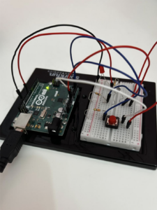
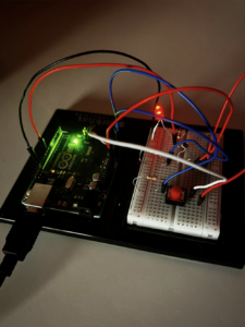
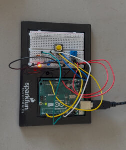
For this week’s assignment, I made a smiley face with two glowing eyes, where they “wink” in between. One of the LEDs brightness was controlled using a photoresistor, and the other turned on/off using a switch.

MATERIALS USED:

Arduino UNO

Breadboard

Photoresistor

10K Ohm resistor

330 Ohm resistor

Switch

LED

Jumper wires

WORKING:

So one of the LEDs are controlled using the photoresistor. It gets brighter when the photoresistor is covered(less light), and vice versa. The other LED is controlled using the switch. The code for it is as follows:

const int button = 2;
const int led1 = 13;
const int led2 = 9;
const int ldr = A0;

int state = LOW; //state of LED1
int brightness = 0; //brightness of LED2
int ldrValue = 0; //photoresistor value

void setup() {
  pinMode(button, INPUT_PULLUP); 
  pinMode(led1, OUTPUT);
  pinMode(led2, OUTPUT);
  
  //serial monitor for debugging
  Serial.begin(9600);
}

void loop() {
  if (digitalRead(button) == LOW) {
    state = HIGH;  //turn LED1 on
  } else {
    state = LOW;   //turn LED1 off
  }
  
  //read photoresistor value and map it to LED2 brightness (0 to 120)
  ldrValue = analogRead(ldr);
  brightness = map(ldrValue, 0, 1023, 0, 120);
  
  Serial.print("LDR Value: ");
  Serial.println(ldrValue);
  
  //control LED1 using switch (physical input)
  digitalWrite(led1, state);
  
  //control LED2 brightness using analog input
  analogWrite(led2, brightness);

  delay(100);  //small delay for stability
}

CHALLENGES :

The challenging part about this was my biggest careless mistake! I put the LED on oppositely (anode and cathode), so I spent a good 30 minutes trying to figure out what went wrong. I also used the serial monitor to help with debugging.

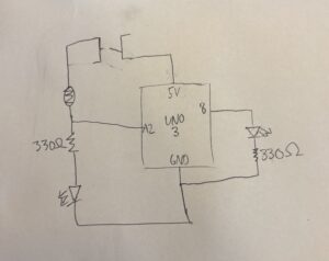
Hand drawn schematic:

LINK TO VIDEO :

https://youtube.com/shorts/UVZ-qTWX1aE?feature=share

IMPROVEMENTS :

I would like the photoresistor-controlled LED to be better, maybe some other form of coding that makes it more…interesting. I also realised that we wink using our eyelids and not the eyes themselves, but overall, as a form of cartoonish smiley-ness, I’m happy with this project. It was a fresh start after the spring break!

Week 9: Analog input & output

Concept:

This project is a reaction timer game built using an Arduino, a push button, a potentiometer, and two LEDs. The main idea is to test how fast a person can react after seeing a visual signal. One LED acts as the “start signal” light — when it turns on, the player must press the button as quickly as possible. The potentiometer controls how difficult the game is by adjusting the random delay time before the signal LED lights up. After the player presses the button, the Arduino measures their reaction time and shows it on the computer screen through the Serial Monitor.

The second LED is used to make the project more interactive by representing the player’s reaction speed through brightness. If the player reacts quickly, the second LED lights up brightly. If the reaction is slower, the second LED is dimmer. This gives instant visual feedback without needing to check the Serial Monitor every time. The whole project is a fun way to learn about digital inputs, analog inputs, and timing functions with Arduino, and it can easily be expanded with sounds, scores, or even multiple players later on.

int pushButton = 2;  // Button pin
int potPin = A0;     // Potentiometer pin
int ledPin = 8;      // LED pin

void setup() {
  Serial.begin(9600);
  pinMode(pushButton, INPUT_PULLUP);
  pinMode(ledPin, OUTPUT);
}

void loop() {
  int difficulty = analogRead(potPin);  // Read difficulty setting
  int waitTime = map(difficulty, 0, 1023, 1000, 5000); // Map to 1-5 seconds
  
  Serial.println("Get Ready...");
  delay(random(waitTime));  // Wait random time based on potentiometer
  
  digitalWrite(ledPin, HIGH);  // Turn LED ON (reaction signal)

  unsigned long startTime = millis();  // Start counting time
  while (digitalRead(pushButton) == HIGH) {
    // Wait for button press
  }
  unsigned long reactionTime = millis() - startTime;  // Reaction time calculation
  
  digitalWrite(ledPin, LOW);  // Turn LED OFF after button pressed
  
  Serial.print("Reaction Time (ms): ");
  Serial.println(reactionTime);
  
  delay(3000);  // Wait 3 seconds before starting again
}

Challenges:

My Arduino Board got stuck in an infinite loop through a test code I ran previously and stopped accepting any further code uploads. Due to this, I had to change my project idea and use a friend’s Arduino to run the code.

New Concept:

This is a simple circuit using 2 LEDs, a potentiometer, and a switch button. The potentiometer controls the brightness of the LED while the other LED is controlled by the button.

Week 9: analog input & output

For this project, we were asked to use both a digital and an analog sensor to control two separate light bulbs. I chose an LDR as the analog sensor and a push button switchas the digital one.

The circuit was designed with both connections set up in parallel, but each individual sensor and its LED were wired in series. That means the LDR is connected to a resistor and then to an LED in one path, while the button switch is connected to a resistor and another LED in a separate path. Both paths share power and ground—so they’re technically in parallel, but operate independently.

My favorite part of the project was seeing how the LDR affected the brightness of the LED in real-time. The more light it receives, the dimmer the LED gets, and vice versa. It was satisfying to see that dynamic shift as I covered and uncovered the sensor.


For the digital sensor, the behavior is much simpler: the LED turns on when the button is pressed and turns off when it’s released. There’s no change in brightness—just a clean on/off action.

One challenge I faced was protecting the LEDs from burning out. I ended up frying three of them before realizing that I needed to be more careful with resistor values and connections. In the end I started disconnecting my board from power before making any changes to the connections which I realize now I should’ve done from the start but I just forgot about it.

For future improvements, I’d love to swap the LDR for a microphone sensor and make the LED respondto sound intensity instead of light. I thinkit would be fun to experiment with how volume or rhythm could control brightness, especially for interactive or musical projects.

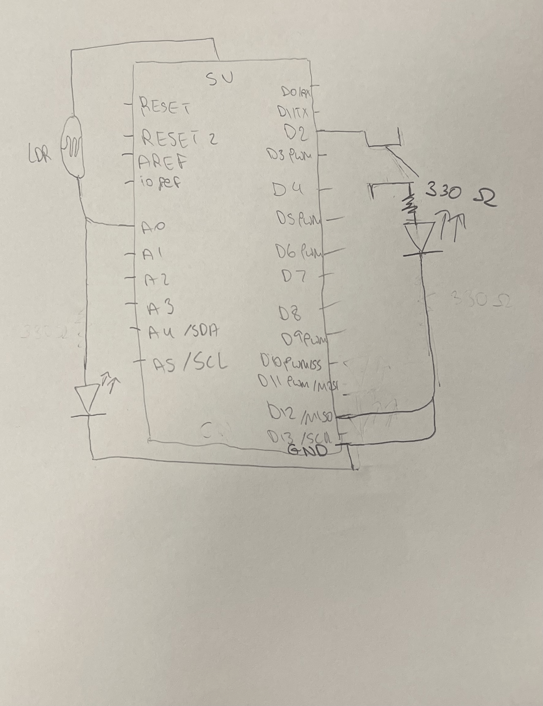
Hand-drawn schematic diagram:

Switch not pushed. LDR exposed to room light.

Switch not pushed. LDR covered.

Switch pushed. LDR exposed to room light.

Week 8: Creative switch

For this project, I got inspired by bowling, and so I wanted to use a  rolling ball to control the LED light. The idea was to turn it into a competition between two players, where the goal is to light up a bulb three times before the other player.

To build this, I created a mini bowling alley out of cardboard. At the center of the alley, there’s a handle wrapped in copper tape. The game starts with the handle tilted at an angle, and each player takes turns rolling a ball, trying to push the handle into the exact center position. When the handle aligns just right, it connects with another piece of copper tape, completing the circuit and lighting up an LED. The first player to do this successfully three times wins the game.

My favorite part of this project was designing the handle mechanism and experimenting with the balance between accuracy and force.

One challenge I faced was adjusting the friction of the handle. At first, it slid way too easily, which made the game too simple and boring. But when I added more resistance, it became too difficult, and no one could win. After asking multiple people to try the game and integrating their feedback I finally reached a state where the game worked as I pictured it at the start and became enjoyable to play.

Things I’d like to improve in the future include adding a digital scoreboard to track each player’s progress and wins. I’d also like to experiment with different materials as cardboard was really hard to work with due to differences in friction between different kinds and cuts of cardboard.

Starting/Losing:

Winning: 

Reading Response 9.b – Making Interactive Art: Set the Stage, Then Shut Up and Listen

This article covers topics like physical interaction and interaction design. The author argues that the artist should have a shift in perspective regarding the expression and interpretation of their own artwork. He argues that artists pre-describe and set their own interpretation, telling the participants how to think and act. 

However, the only primary task an artist has is the interactive framework. Once this is done, the artist should “shut up and listen”. The static artwork must shift into a dynamic performance, with the audience being the central character. The conversation doesn’t only rely on the artist letting the audience speak, but also in listening to the audience, their comments and analysis. 

This reading made me realise how much collaboration and listening is important in creating artworks. I realised that over-explaining artworks and projects really takes away from the whole experience of the audience. The true beauty in immersion and interaction lies in the audience being allowed to freely communicate with the artwork. This also allows both of us to interact and learn from each others’ interpretations, creating a wider space for creative freedom and expression. 


Reading Response – Physical Computing Greatest hits (and misses)

This article explores various themes in physical computing, their mechanisms and applications. Many different projects are shown here, including theremin-like instruments, gloves, video mirrors, dolls and pets and Scooby-Doo paintings. 

The ones that I found most interesting are definitely the mechanical pixels and the multi-touch interfaces. The mechanical pixels were very similar to many projects I saw in fashion, where there are moving parts in structured ball gowns; adding mechanical components to clothing was pretty interesting. These certainly aren’t very practical, but rather serve as a structured display of fashion and aesthetics. I wondered whether the same technique was being applied here. I have interacted with multi-touch interfaces before at art exhibitions and installations at Expo 2020 Dubai, where the movements of my hands would direct shooting stars and flying comets. This sort of physical computing has always fascinated me, it really feels fun and interactive. 

Overall, I found many of the projects very inspirational and interesting. Physical computing is a very new discipline for me, and these projects helped me see the trends and themes evolving within the broad field. These projects definitely serve as a foundation for many great projects, some hits and some misses.


Arduino: analog input & output

This week I used both an analog and a digital sensor to control two LEDs in different ways. I used the ultrasonic distance sensor to measure distance. For the digital sensor. My setup controls two LEDs: one blinks and the other changes brightness using PWM.

Here’s how it works:
LED1, connected to a regular digital pin, blinks faster when an object is closer and slower when it’s farther away. The delay between blinks is based on the distance in centimeters. So the closer the object, the faster the LED blinks. If the object is far, the LED blinks slowly.

LED2, connected to a PWM pin, changes brightness based on the same distance. But instead of getting dimmer when the object is far (which is more common), I made it do the opposite—it’s dim when the object is close and bright when it’s far away. I know it’s the reverse of what people usually do, but I wanted to try something different and see how it looked in action.

the code :

// Pin definitions
const int trigPin = 7;     // HC-SR04 trigger pin
const int echoPin = 6;     // HC-SR04 echo pin
const int led1Pin = 2;     // LED1 pin (digital)
const int led2Pin = 3;     // LED2 pin (PWM)

// Variables
const int maxDistance = 255;  // Maximum meaningful distance (cm)
int distance = 0;             // Measured distance in centimeters
int brightness = 0;           // Variable for brightness

void setup() {
  Serial.begin(9600);
  pinMode(led1Pin, OUTPUT);
  pinMode(led2Pin, OUTPUT);
  pinMode(trigPin, OUTPUT);
  pinMode(echoPin, INPUT);
}

long getUltrasonicDistance() {
  digitalWrite(trigPin, LOW);
  delayMicroseconds(2);
  digitalWrite(trigPin, HIGH);
  delayMicroseconds(10);
  digitalWrite(trigPin, LOW);
  return pulseIn(echoPin, HIGH);
}

void loop() {
  // Measure distance
  distance = 0.01723 * getUltrasonicDistance();
  
  // Cap the distance reading
  if(distance > maxDistance) distance = maxDistance;
  if(distance < 2) distance = 2;  // HC-SR04 minimum range
  
  // Serial output
  Serial.print(distance);
  Serial.println(" cm");
  
  // LED1: Blink with distance-dependent delay (capped)
  digitalWrite(led1Pin, HIGH);
  delay(distance);
  digitalWrite(led1Pin, LOW);
  delay(distance);
  
  // LED2: Brighter when closer, dimmer when farther
  //brightness = map(distance, 2, maxDistance, 255, 0); // Inverted mapping
  //brightness = constrain(brightness, 0, 255); // Ensure valid PWM
  //Serial.println(brightness);
  brightness = distance;
  analogWrite(led2Pin, brightness);

video:

https://drive.google.com/drive/u/0/folders/1Kk2lkQgoAyybXSYWVmY2Dog9uQVX_DMq

future improvement:

In the future, I’d like to add sound that reacts to distance, like pitch changes as you move closer or farther. I also want to make the project more interactive overall—maybe by adding more sensors or letting users trigger different responses through movement or touch. This would make the experience feel more playful and alive.

schematic:

Week- 9 reading

This week’s readings made me think about how important it is to be okay with things not always working out. In Physical Computing’s Greatest Hits and Misses, I liked how it showed both the successful projects and the ones that didn’t go as planned. That felt real. I often feel like everything I make has to be perfect, but this reminded me that trying new things and failing is part of the process. It also made me wonder—what really makes something a “failure”? If people still interact with it or feel something from it, maybe it still has value. I want to be more open to things going wrong, because those moments can lead to better ideas.

The second reading, Making Interactive Art: Set the Stage, Then Shut Up and Listen, really stayed with me. I’m used to explaining my work a lot or trying to get people to understand exactly what I meant. But this reading made me realize that sometimes the best thing I can do is let go and let the audience explore for themselves. I don’t fully agree with the idea that artists should just “shut up,” because I think some guidance can help people connect. Still, I like the idea of trusting people more. It made me think about how I can make work that gives people space to feel, move, and react in their own way, without me controlling every part of the experience.

Week 9 Reading

One of the most interseting concepts found in “Physical Computing’s Greatest Hits” I found was the tilty tables. While the concept of tilting and how it can alter the objects on a surface is so very intuitive to us, the tilting table adds a degree of complexity compared to something live a wave wall. The tilting allows for another, interesting way for audiences to interact with art in a non-conventional way that is still very rooted in modern day physics.

One of the most out there ideas was also the meditation helpers; devices designed to take away stimulus. This also struck me as very counter-intuitive yet fascinating. Normally, we think about taking away stimulus when it comes to being in a state to meditate, yet this machine attempts to connect the user to the compuation through the interpretation of a series of sensors in a way I think fuses technology and biopsyhcology in a fascinating way.


From the other article, I found the message to be very important and true. Similar to how Norman said doors that need signs are poorly designed, I think an artwork being able to stand alone with less surrounding context is in some shape or form a testament to its thoughtful design. Because the truth is, if one designs their artwork well enough, operation should be intuitive to the user.

The way the article says to indicate what the user should do with the art is so obvious, but when we ourselves are creating art, from an opposing perspective, it is definitely true that these things are just not as obvious as they would if we were not the artist.

Another important note from the article is to listen for feedback. Unlike other mediums, this one is more able to changed over time with feedback. So when for users there is a disconnect in what needs to be done and what they are trying to do, the artist should really take that into account to improve their work.

Week 9 – Production

Initial Idea

The goal of this project was to explore the interaction between analog and digital sensors and how they can be used to control outputs creatively. Specifically, the task was to use at least one analog sensor and one digital sensor to control two LEDs, one through digital means (on/off) and the other through analog means (brightness control). The initial idea was to keep the components simple but effective: a push-button as a digital switch and a potentiometer as an analog input, controlling a red and green LED, respectively.

Video demonstration

Execution

The red LED was connected in series with a 330-ohm resistor and controlled by a push-button, which toggled it on or off based on the button state. The green LED was also connected with a 330-ohm resistor and its brightness was adjusted using a 10k potentiometer wired to an analog input pin. The analog value was read from the potentiometer and mapped to a PWM value to vary the green LED’s brightness.

Here is a diagram:


const int potPin = A0;
const int buttonPin = 2;
const int ledDigital = 10;
const int ledAnalog = 9;

bool ledState = false;

void setup() {
  pinMode(buttonPin, INPUT_PULLUP); // button active LOW
  pinMode(ledDigital, OUTPUT);
  pinMode(ledAnalog, OUTPUT);
}

void loop() {
  // Read potentiometer value
  int potValue = analogRead(potPin); // 0 - 1023

  // Map it to PWM range
  int brightness = map(potValue, 0, 1023, 0, 255);
  analogWrite(ledAnalog, brightness);

  // Read button
  if (digitalRead(buttonPin) == LOW) {
    delay(200); // debounce
    ledState = !ledState;
    digitalWrite(ledDigital, ledState);
  }

  delay(50); // loop delay
}


Highlights 

  • The logic worked exactly as planned: the button cleanly toggled the red LED, and the potentiometer provided smooth brightness control for the green LED.

  • The circuit was clean, and the schematic clearly represents the wiring and design intent.

  • I’m proud of how the components were chosen and integrated in a way that’s both simple and pedagogically effective, perfect for demonstrating basic input/output handling on Arduino.

What Could Be Improved

  • Debouncing the push-button in code could be refined further to prevent unintended toggles.

  • A creative twist (e.g., combining analog and digital inputs for more complex LED behaviors or using a different type of analog sensor like an LDR) could elevate the interactivity.

  • Next time, I might also add a small OLED screen or serial output for live feedback on sensor values for better debugging and visualization.