
Considering the position of interactive artwork, this reading has prompted me to contemplate my perspective on interactivity. Tigoe’s perspective resonates with me, viewing interactive artworks as akin to performances. The artist constructs a stage for interactors, transforming them into the performers within this theatrical space. Andrew Schneider’s piece, while appearing as a fixed narrative from a distance, offers diverse interactions in group settings, providing a more rewarding experience than a singular interpretation of museum paintings. Exploring the greatest hits and misses further complicates this perspective. Even seemingly straightforward interactions, like an LED lighting up upon approach, possess untapped potential for development. The originality of an idea lies not in the interaction itself but in the contextualization and open interpretation it offers. This nuanced approach to context and interpretation is particularly appealing. It leads me to contemplate the possibility of creating a more contextualized theremin, building on the potential for exploration within a defined setting.
Category: Fall 2022 – Shiloh
Musical Instrument (Nourhane & AYA)
CONCEPT:
This assignment was complicated in terms of finding a concept for it. We had a couple of cool ideas to do at the beginning (ie. soda cans drums) but their implementation was a fail. We decided to use our favorite part of the kit: the ultrasonic sensor, and get a concept out of it.
Both our previous assignments used ultrasonic sensors as distance detectors. So we thought to base this assignment on the same concept.
This musical instrument is inspired by the Accordion instrument (with a twist):

Using a plastic spiral, we are mimicking the same movement of an accordion to produce different notes. The distance between the hand and the sensor is what is producing the different notes (each distance range was assigned a different note). The circuit has a switch to turn on/off the instrument.
Here is a video of what I’m talking about:
CODE:
Again assembling the circuit was a hard part but it worked! The code is pretty simple and consists of an ultrasonic sensor and a switch. The `loop` function repeatedly triggers the ultrasonic sensor, measures the distance to an object, converts it to centimeters based on the speed of sound. Depending on these values, it determines whether to play a musical note. If the distance is outside a defined range or the force is below a certain threshold, it stops playing the note. Otherwise, if sufficient force is applied, it maps the distance to an array of musical notes and plays the corresponding note using a piezo buzzer.
int trig = 10;
int echo = 11;
long duration;
long distance;
int force;

void setup() {
  pinMode(echo, INPUT);

  pinMode(trig, OUTPUT);

  Serial.begin(9600);
}

void loop() {
  digitalWrite(trig, LOW); //triggers on/off and then reads data
  delayMicroseconds(2);
  digitalWrite(trig, HIGH);
  delayMicroseconds(10);
  digitalWrite(trig, LOW);
  duration = pulseIn(echo, HIGH);
  distance = (duration / 2) * .0344;    //344 m/s = speed of sound. We're converting into cm


  int notes[7] = {261, 294, 329, 349, 392, 440, 494}; //Putting several notes in an array
  //          mid C  D   E   F   G   A   B

  force = analogRead(A0); //defining force as FSR data


  if (distance < 0 || distance > 50 || force < 100) { //if not presed and not in front

    noTone(12); //dont play music

  }

  else if ((force > 100)) {  //if pressed

    int sound = map(distance, 0, 50, 0, 6);  //map distance to the array of notes
    tone(12, notes[sound]);  //call a certain note depending on distance

  }


}
REFLECTION AND IMPROVEMENTS:
Though I found this assignment difficult, I enjoyed the process of implementation and finding a concept. If I could improve the instrument, I would work on the notes and their frequency to sound more natural. Now it sounds like an EKG machine with notes instead of an instrument, but I think it fulfills the requirement of fictional instrument.
Unusual Switch
Concept
I was looking around in my room to find something that uses simple motion to work, and I thought of my drawers. This is how I came up with my drawer switch. I set up the circuit, and taped two large foil pieces to the coils and onto the inside of the drawer as shown in the photo below:
Challenges:
Due to illness I had to miss the previous class, so I relied on Youtube and online tutorials to learn how to create circuits and how switches work. Because of that it took me quite a while to understand them, and hence why the end result looks a bit more crowded than my classmates’.
Demo:
Reflection:
Overall I am satisfied with my idea and execution, and I am very glad I managed to learn about circuits, how to manage a breadboard and how to use Arduino even though it took longer through the internet.

Midterm Project
Concept
I recently made a website whose theme is based on galaxies and its accompanying features. ie Gravity, rotation about a center etc. I draw inspiration from that idea to create a shooting game, one that obviously features a protagonist’s spaceship shooting enemies.
Resources: https://drive.google.com/drive/folders/1XpSZpyi1ZLYHNcuS6oSnQvXkh0091LMh?usp=sharing
I anticipate adding a feature that will animated ellipses that imitate the movement of stars in the galaxy; so far, I think that is the task that may prove difficult.
Final Project and Reflection
The Demogorgon by Abigail and Ahmed
Concept & Design
Initially, we wanted to create a simple art project using multiple servos to control panels. That was very short-lived. Our concept slowly went from a simple interactive art piece that looked pretty to an interactive monster called a Demogorgon from the Netflix series Stranger Things. We wanted to make something interesting that could catch users’ attention longer than an art piece. Since our Demogorgon was not going to necessarily be a game with a winning or losing outcome, we still had to figure out ways to make it more interactive. We took our assigned reading: Emotion & Design: Attractive Things Work Better by Don Norman into consideration and decided that in order to convey what we wanted we needed to make the Demogorgon come to life and make it something that is interesting to look at in addition to the code and interact itive component. To make both the interactive component and the Demogorgon fit nicely together, we decided to use certain scenes of the show to inspire the movements. In the show, the protagonist Eleven defeats a Demogorgon by putting her hand up since she has the ability to manipulate living beings however she wants through her hands. This inspired us to make it so the user is able to open the Demogorgon face flaps we build as their hand gets closer to them through a distance-measuring sensor. As we went along with our project, we realized how ambitious we were with our concept and simply tried our best to make it happen.
For our project, we used the ultrasonic distance measuring sensors, LED lights, flex sensors, 3-d printing, cardboard, wood, acrylic, and paint. Though we went through a lot of hiccups including but not limited to spending hours soldering cables we ended up not using, one of us going into isolation because of COVID-19, short circuits, and re-thinking our concept a few times… we kind of did it.
Interaction Design
Physical
This was a very time-consuming aspect of project, especially since we really wanted it to make look as much as a Demogorgon’s head as possible with what we had. The wood that was available to us was pretty thick and we knew we had to cut holes in it to make openings for the 3-d printed and handmade Demogorgon flaps so it was going to take a long time to cut the wood and put everything together. Luckily, the woodshop was nice enough to let us borrow a Jigsaw so even though it was still a tedious process of drilling two holes where we wanted one hole for the flap to be and then using the Jigsaw to go in and follow the outline, it made it go a lot faster. We did this process seven times. For the flaps of the Demogorgon, at first, we 3-d printed three of them but it was taking a long time so for the last four we decided to build them out of cardboard for time’s sake. The 3-d printed ones still looked pretty cool though and definitely added an appeal to it, in our opinion. Plus, the different materials fit the Demogorgon vibe. We painted and added red and white for the skin tone. We also had to make longer cables to reach the Demogorgon flaps when our Arduino port is hidden beneath the box/head.
Arduino Code
Our Arduino code controlled the flex sensors, server motors, and ultrasonic measuring sensor. The sens0rs were mapped to values from 0 to 180 and then output at different rates depending upon the configuration. The output rates helped stabilize the servo motors which were prone to jittering.
We used some sources for these pieces:
Code for the servo motors with Ultrasonic sensor:
// Clears the trigPin condition
digitalWrite(trigPin, LOW);
delayMicroseconds(100);
// Sets the trigPin HIGH (ACTIVE) for 10 microseconds
digitalWrite(trigPin, HIGH);
delayMicroseconds(100);
digitalWrite(trigPin, LOW);
// Reads the echoPin, returns the sound wave travel time in microseconds
duration = pulseIn(echoPin, HIGH);
// Calculating the distance
distance = duration * 0.034 / 2; // Speed of sound wave divided by 2 (go and back)
// Displays the distance on the Serial Monitor
distanceMapped = map(distance, 0, 70, 22, 180);
distanceMapped=constrain(distanceMapped, 30, 180); //this allows the output to stay between the constraints. without this it goes up to like a few thousand for some reason

int distanceMappedforOuter = distanceMapped + 10; // the outer petals will open wider, to give a flared look

myOuterServos.write(distanceMappedforOuter);
delay(75);
myInnerServos.write(distanceMapped);
delay (75);
Code to control servos with the Flex Sensors:
int OutsideFlexValue;
int InnerFlexValue;

int servoPositionInside;
int servoPositionOutside;

OutsideFlexValue = analogRead(OutsideFlexPin);
// delay(15); //adding slight delays to make it stable

InnerFlexValue = analogRead(InsideFlexPin);
// delay(15);

servoPositionOutside = map(OutsideFlexValue, 170, 500, 0, 180);  // need it to rest at a midwards position
servoPositionOutside = constrain(servoPositionOutside, 0, 180);
// int round10(int servoPositionOutside);

servoPositionInside = map(InnerFlexValue, 100, 360, 0, 180);
servoPositionInside = constrain(servoPositionInside, 0, 180);

// servoPosition = constrain(servoPosition, 45, 180); //for the servos that go beyond 180

myOuterServos.write(servoPositionOutside);
delay(75);
myInnerServos.write(servoPositionInside);
delay(75);
To reduce jittering the following line of code was added to constrain the servo motors from going beyond set parameters.
distanceMapped = map(distance, 0, 70, 22, 180);
distanceMapped=constrain(distanceMapped, 30, 180); //this allows the output to stay between the constraints. without this it goes up to like a few thousand for some reason
p5.js Code
Our p5.js code focused on the screen that the user would see and use to interact with our Demogorgon. We used the game state and included a starting screen followed by an introduction and instruction screen. We realize not everyone may know what a Demogorgon is or have watched Stranger Things, so we made it feel an arcade game you would go up to, get an introduction and instructions for, and start playing around with it whether or not you fully grasp the inspiration behind it.
There was an issue that we couldn’t quite figure out. After adding the second sound, the audio would start glitching after a while. At first, we thought it was just the sound so we tried it out with different sounds but no luck. When we decided to search if there was a solution or if the code was wrong, we found a thread from 2020 that discussed how the newest versions of p5.js have audible distorted effects on Chrome and there is no fix yet. The audio just keeps getting distorted and eventually the window shuts down and you have to refresh the page.
The p5js code can be accessed on Abigail and I’s p5js sketches directory on the p5js website.
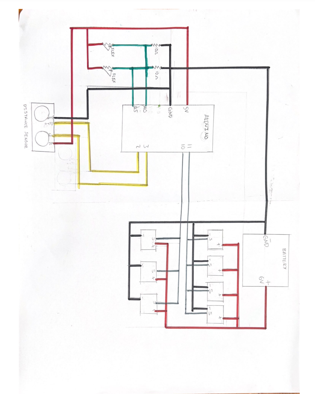
Circuit Diagram for the Project:
Since our project was rather complicated and needed a lot of cables, we decided to draw a schematic for it.
Problem(s) 🙁
Though we knew what needed to be communicated between the Arduino and p5.js, it worked only sometimes. The problems started when we started off by checking out the Arduino MEGA from the IM Lab and tailoring our code to it. However, since we got an extension past the last day to return items to the IM Lab due to reasons neither of us could control, we had to switch back to the Arduino we received in our kit. For some reason what we had did not work after that and we had to figure out why. We switched up the code again but only some parts of it would work and only sometimes as p5.js kept shutting down and the serial connection kept disconnecting. We tried to ask for help through friends and Facebook groups. No one was able to help us though and as we ran out of time we accepted our fate. The Demogorgon beat us (sorta).
Some testing and progress videos:
Testing the Flex sensors interfaced with the servo motors:
Testing the ultrasonic distance sensor interfaced with the servos:
Problems that we ran into and how we tried to solve them:
- The first problem we ran into pretty early on was a jittering in the servo motors that could not be controlled. The jittering would make the servos move even when the code was not running. After some debugging, we realized that the problem originated with the 5v supply on the main board, and switching the servos to an external power source would reduce it. It could be made smoother by adding another earth wire connected to one of the unused GND pins
- Another problem we ran into was the 3d printing of some of the parts. The models we had used were pulled off the internet and were supposed to be printed within a few hours but the first 3 iterations were all just a mess of melted filament since the model would move around. After consulting the lab assistants we realized scraping the surface of the building area of the printer solved the issue immediately.
- A bug that we ran into while working on the Arduino-p5js serial communication was that the communication would halt and spout an error ‘Failed to open serial port’. We realized that this could be fixed most of the time by closing the serial monitor on the IDE. However, at one point it persisted despite restarting, and according to some forums, it was a problem with incompatible drivers that plague computers with versions of Windows later than 10.
- Another bug that we ran across that caused us the most trouble was that the p5js terminal would not work or crash periodically after adding sound effects that were to be played on the terminal. We could not find a viable solution to this problem.
- We did not realize until the last moment that there were in fact some subtle differences between how Arduino mega and uno work. Other than the size and ram, there is also a difference in how we set up the ultrasonic distance sensor by following this tutorial. There were other differences too that for some reason broke the code when we tried running it on the Uno however we cannot seem to locate the exact piece of code that caused it.
Future Improvements:
- I think we focused on Professor’s warning that the physical component was going to take a really long time too much. Our concept depended a lot on being appealing to the audience so we wanted to make sure we made our Demogorgon look really good and spooky. However, we spent so much time on it considering the limited time we had that we did not think about how buggy the code would be considering everything we were trying to make it do at once.
- Figure out a more stable way for communication between p5js and Arduino.
- Use a stable operating system that causes the least amount of problems with regard to drivers
- Use a stable search engine to run p5js smoothly
- Employ a better and more rigorous documentation method along the progress of future projects to create a seamless reference system in case of mistakes. We spent way too much time trying to debug without knowing what resources I had accessed before or how we had implemented stuff.
Project Reflection:
This project was really challenging yet somewhat rewarding. I think personally, I would like to spend more time researching the project before actually starting with it. The technique of ‘forcing’ a project or completing it by brute force is not something that can be accomplished with such projects. This project also gave me experience with interfacing Arduino boards with p5js. And showed me how important it is to start early with developing a code that can work seamlessly, especially with tools that are relatively new to me, and are already known to have caused problems.
The project was also an opportunity for me to gain more knowledge and technical know-how from the Professor who has been teaching people about creative robotics for a long time. I was able to pick his brains but failed to capitalize on him as an incredible resource towards the final stretch which led to failure to achieve a favorable final project. It made me realise how important it was to reach out when there is a problem hampering progress.
Moreover, the project allowed me to push my boundaries to the extreme. Not only was it intellectually strenuous, requiring a great amount of technical know-how and problem-solving abilities but also physically straining and intensive. I am extremely disappointed in not being able to assemble the final project in a way that was, well, final. However, this project has only given me more drive to try and learn more about p5js, and Arduino and how these two tools can be merged to create working machines beyond their apparent limits.
Arduino code:
Aisha – Final Documentation
Initially, I wanted to create some sort of ball-scrolling game where a ball has to jump from platform to platform without falling down. However, I struggled with creating the 3D platforms for it and having it rotate so I then moved on to my next idea. As a kid, I used to love the game ‘Doodle Jump’, a mobile game where you have a doodle and have it jump from platform to platform, avoiding the enemy and falling down. Therefore, I decided to create my own variation of the game called ‘Hop’.
Creating the code on p5js was the biggest challenge for me. I had issues with having some platforms show, having the doodler not scroll past the screen as well as all through platforms. But with the help of https://codeheir.com/2021/03/13/how-to-code-doodle-jump/ and codeTonight I managed to fix these issues.
I printed an instructions page for users to look at before playing the game which looked like this: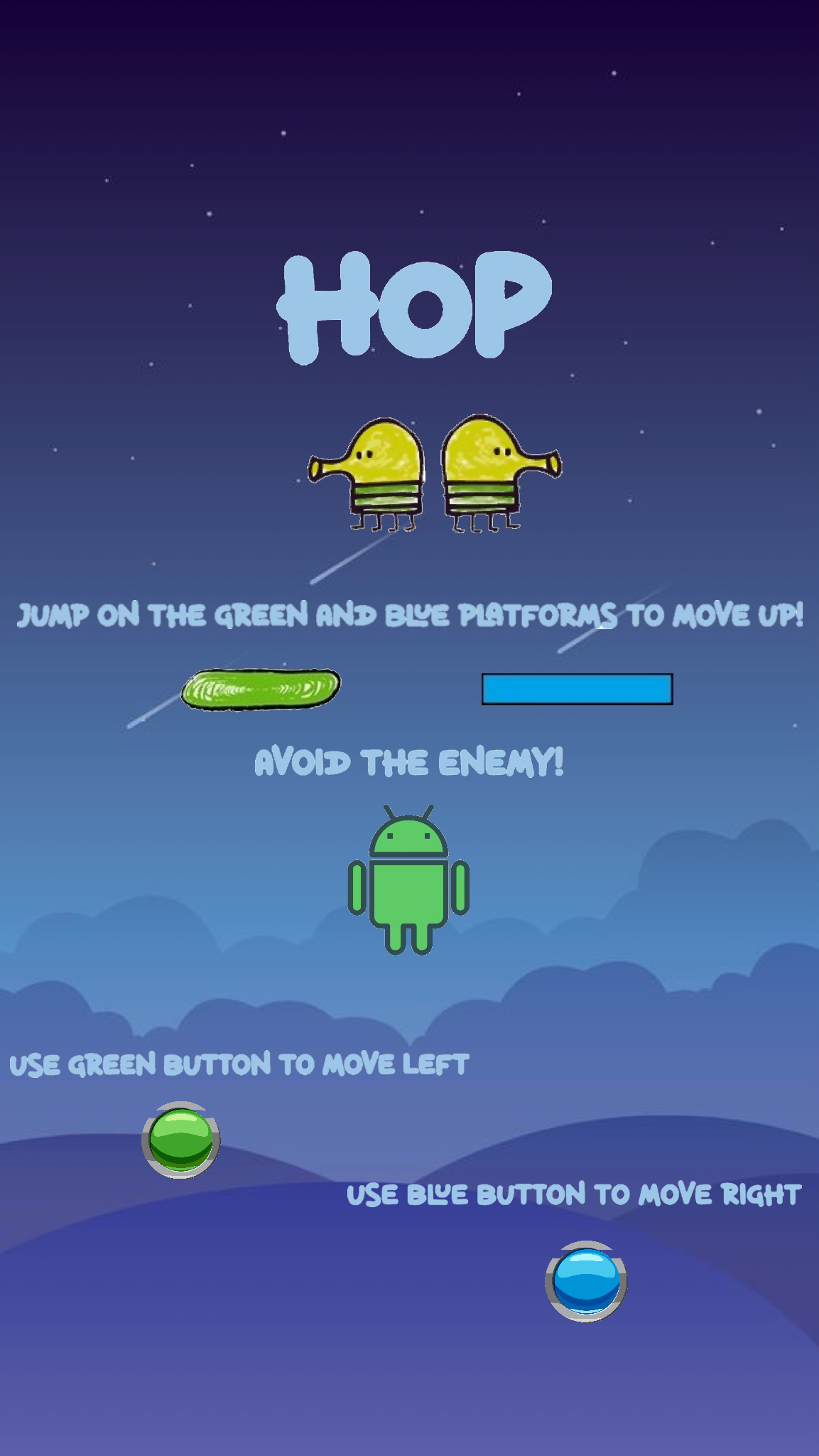
Here is a link to the p5 and Arduino code: https://editor.p5js.org/aishaalketbi_/sketches/KQIfnEUMj
This is the game:
I’m really proud of the game itself, I enjoyed coding it and whilst doing it I realized I loved coding games in general.
Future improvements:
- I would like to make my controls look prettier. This is what it looked like:
- I wanted to add white platforms and have them disappear when the player jumped on them however I couldn’t figure it out and decided to remove it.
Final Project Documentation
I can’t believe how fast this semester went, and especially with this class. I came in to enter to IM as a senior with legal studies as my major and no idea on coding. I ended this semester with presenting a project that involved code on both P5JS and Arduino that I was able to present too many people and have them ask me and me able to explain how code and circuits work. if you asked me prior to this if I would have been able to do something like this, I would have probably said there is no chance but now thanks to this class I was able to present something that I’m proud of and something that I was able to put my heart into.
Concept & Design
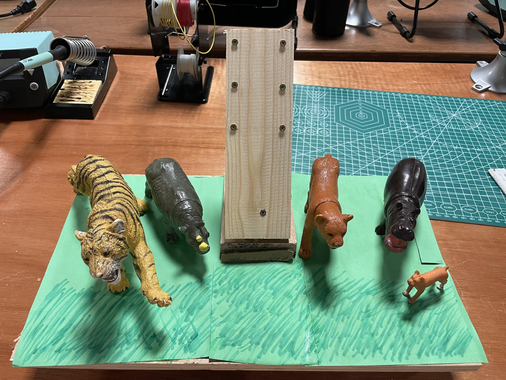
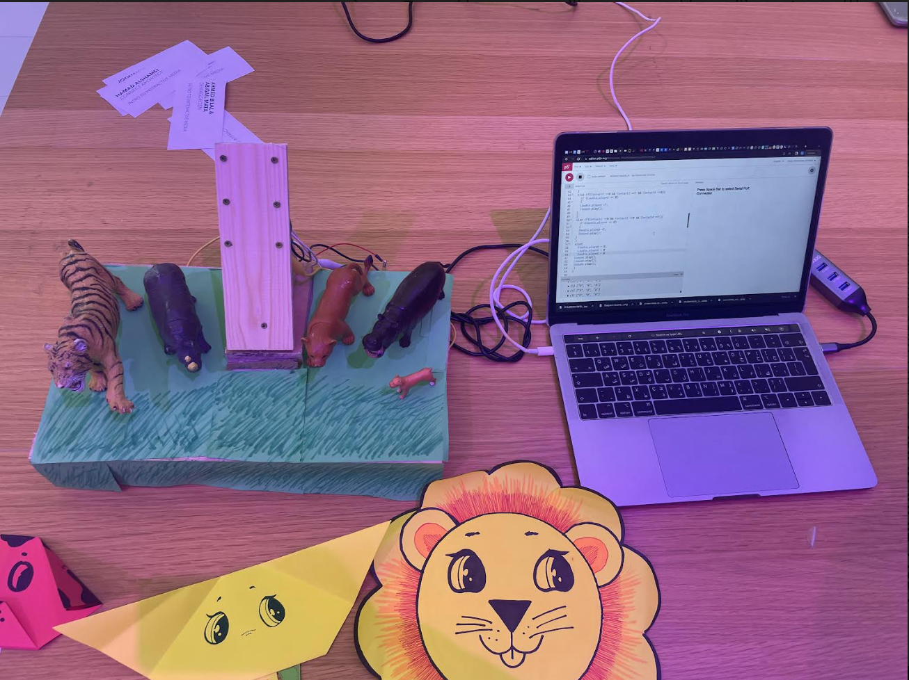
the concept of my game came from seeing my nephew who was two years old playing with my niece who was six months old. he was showing her different animals and making their noises, I then thought to myself I could probably make this into my final project, and it would be fun and educational. I used P5 to communicate the sound that I wanted to portray and Arduino to know when the circuits complete and to play my sound. My design was a stage that had the different photos of the animal’s on top of a rock. the inspiration behind it was the pride rock from 9 king where the different animals surrounding would see them raise Simba. I implemented that idea with the different animals in the field looking over the animal that the that player would place and play the animal sound.
Code P5js
The code was my toughest challenge, although we have been working on it for the entire semester, I felt like there was a lot that I struggled with bugs and parts that I didn’t understand. I used some of the examples that we learned in class and switched out the light bulbs with the sound that I wanted the circuit to play. I had the very complicated time with creating event else statement for each individual sound that I had to then connect. I then ran into a big problem once that started to work which was being unable to stop the sound from being repeated again and again and i really did not know how to fix it.
let Contact2;
let Contact3;
let Contact4;
let Eaudio_played = 0
let Laudio_played = 0
let Daudio_played = 0


function preload() {
  soundFormats("mp3", "ogg");
  Esound = loadSound("Esound.mp3");
  Lsound = loadSound("Lsound.mp3");
  Dsound = loadSound("Dsound.mp3");
}
 if (Contact2 ==1 && Contact3 ==0 && Contact4 ==0){
    if (Eaudio_played == 0)
      {
        Eaudio_played = 1
         Esound.play();
      }
 }
 else if(Contact2 ==0 && Contact3 ==1 && Contact4 ==0){
   if (Laudio_played == 0)
   {
   Laudio_played =1;
   Lsound.play();
 }
 }
 else if(Contact2 ==0 && Contact3 ==0 && Contact4 ==1){
   if (Daudio_played == 0)
   {
   Daudio_played =1;
   Dsound.play();
 }
 }
 else{
   Eaudio_played = 0;
   Laudio_played = 0
   Daudio_played = 0
 Esound.stop();
 Lsound.stop();
 Dsound.stop();
 }
}
With help from Nouf I tried to create a stop sound feature which worked if I added another I’ll statement to every other line which I did. I had to then communicate Arduino 2P5 and set every single code since I was using three different outputs and one for when nothing would be happening.
if (data != null) {
    // make sure there is actually a message
    // split the message
    let fromArduino = split(trim(data), ",");
    // if the right length, then proceed
    if (fromArduino.length == 3) {

      // only store values here
      print(fromArduino)
      Contact2 = fromArduino[0];
      Contact3 = fromArduino[1];
      Contact4 = fromArduino[2];
Arduino
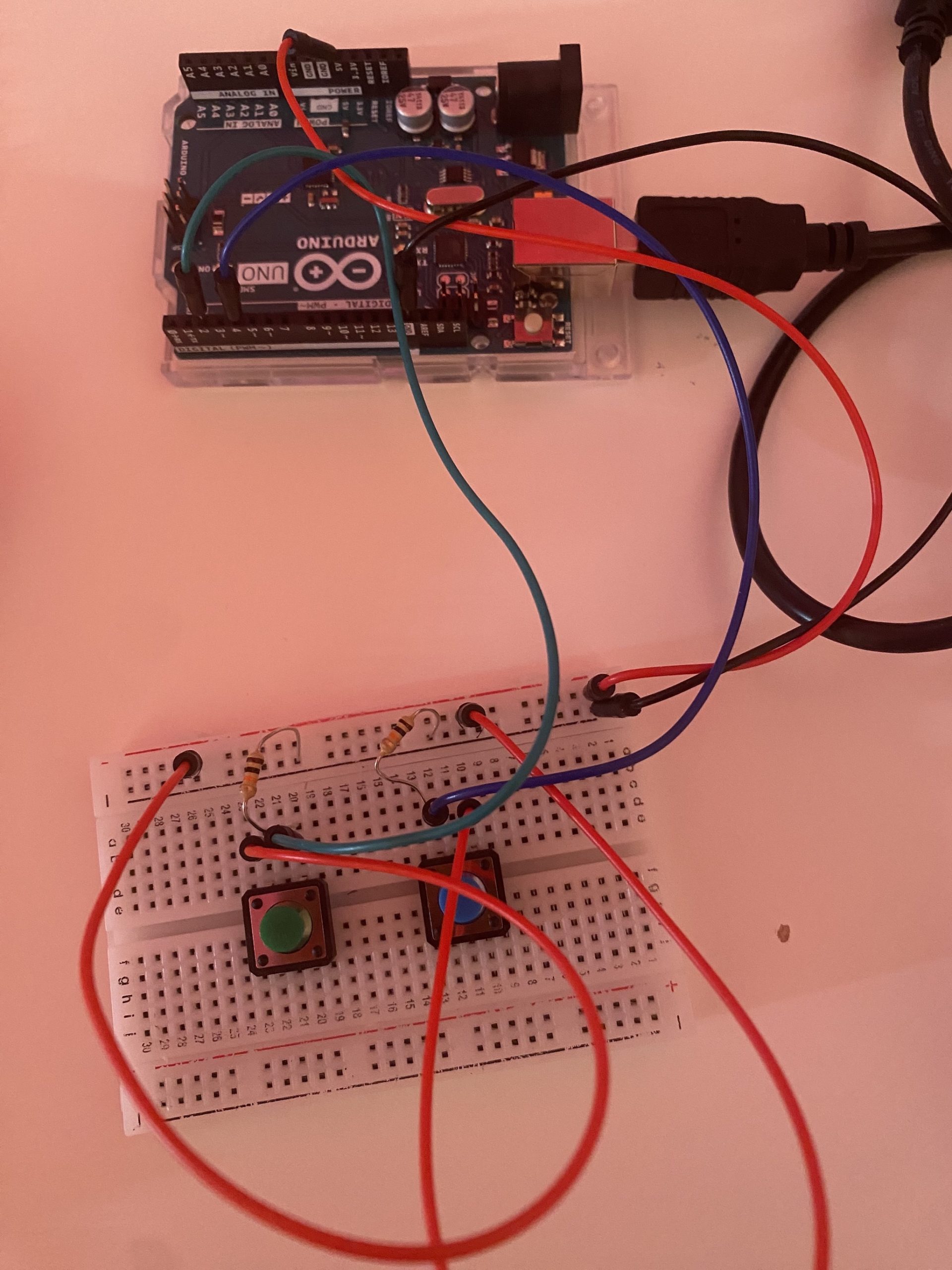
My Arduino code was used to describe three different circuits each of these circuits would be continuously running and my different animal sounds would act like a switch to connect the circuit. Once each of these switches is connected the laptop is able to create a sound that was uploaded to the P5 software. A big issue that I was having was that the animal sounds kept playing randomly and I didn’t know why I then decided to print out what was going on and I decided that I would read the values without anything happening a couple of times. I thought that the problem was with the resistor but I later found out that it was due to me not having an actual button I had to connect to wires one to the pin and one to the back into each resistor and another one to the five volts and another one to the ground. I was then able to use crocodile wires to connect the five faults wire to the near that I screwed to the back of my board and the other crocodile wire to the back of the other nail and use copper wire to create to connect the circuit on the back of the photo. I would create a going circuit with each animal having a different placement for the tape one in the top one in the bottom and one in the middle.
void setup() {
  Serial.begin(9600);
  pinMode(2, INPUT);
  pinMode(5, INPUT);
  pinMode(8, INPUT);
  // start the handshake
  while (Serial.available() <= 0) {
    Serial.println("0,0"); // send a starting message
    delay(300);            // wait 1/3 second
  }
}

void loop() {
  // wait for data from p5 before doing something
  while (Serial.available()) {
    int Contact2 = Serial.parseInt();
    int Contact3 = Serial.parseInt();
    if (Serial.read() == '\n') {
      digitalRead(2);
      digitalRead(3);
      int lion = digitalRead(2);
      delay(1);
      int elephent = digitalRead(3);
      delay(1);
      int dog = digitalRead(4);
      delay(1);
      Serial.print(digitalRead(2));;
      Serial.print(',');
      Serial.print(digitalRead(5));
      Serial.print(',');
      Serial.println(digitalRead(8));
    }
  }
}
What I’m proud of
the thing I’m most proud of in this project is my code. From someone who started this course thinking that I’ll just be able to understand a bit I think I exceeded my own expectations of myself. By step-by-step learning and practicing I was able to then think of how to use if statements and how to create functions and arrays which is something that i didn’t even know of before I started this. I really like the creativity that the class and the professor kept continuously pushing throughout the semester and I think that atmosphere pushed me and I’m also proud of my creativity and how I was able to use that in a different medium than I’m used to.
Something else that I really liked, and I was so happy to see at the showcase was a family with kids that would come and the little boy told me that he liked animals and that he wanted to play my game. after playing my game and hearing the lion roar, he really had a smile across his face and his sister wanted to try the dog which once she heard she felt very astonished by. after 15 minutes I took a 5-minute break and came back to see the little kids playing with my game again. their parents came in and told me that they liked it so much that they told them that they wanted to come to my station again. that was my highlight of the showcase since my game was loved by its intended audience more than I expected
Future
I really wanted to make the animal sounds play louder and play more consistently. I would have some bugs sometimes when the copper tape wasn’t placed exactly right on both screws it would not play the sound. you had to move it a couple of times for it to work. I could have tried using another thing with wood pieces that would connect every time because they would fit into place instead of copper tapes that you would have to push. Someone also gave me the idea of having a barcode that would read whenever the animal was placed into the area so it would make one spot for all the animals and that spot would play the animal sound.
Feed No Face 2.0: Final Documentation
This is the final documentation for Intro to IM! Here is the link to the p5.js sketch with the Arduino code. For my final project, I decided to change it from Live Fruit Ninja to Feed No Face 2.0, which built on top of my midterm project. At first I wanted to do something different from my midterm, but during the process of making Live Fruit Ninja I lost interest and felt like the concept was pretty similar to my midterm project anyway. In the end, I feel like it was a good decision to go back to my midterm because I had a lot of fun improving the project and adding the physical components. So here are the steps to reaching the final product of my project.
Interaction Design: Physical Components
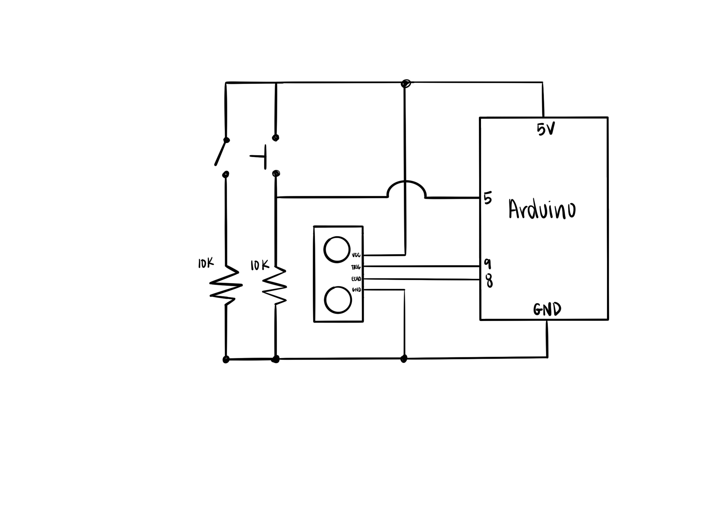
For the physical components of my project, I had two buttons: one main arcade button to eat the food that is falling on the screen and a lock switch to start/restart the game. I also used the distance sensor to get the measurements of the physical character and mapped it to the character on the screen. Here is the schematic of my circuit:
During the process of building this, I spent the most time soldering the panel buttons. At first, I just had everything on a breadboard and didn’t use a lock switch for the start/restart of the game. This made it a lot simpler to build, since I was planning on having everything on the breadboard and just using that. But then I decided to create a case for the Arduino and breadboard, which meant incorporating the arcade button. The arcade button was a better interaction compared to the small push button, but I struggled with the wiring for quite some time. Basically, the soldering wasn’t really an issue, but it was getting the wires to be the correct length. Since my box wasn’t completely assembled, I guessed for the length of the wires. It was too long at first, so I kept trimming until it was too short, which meant I had to resolder it. The next time I used stranded wires, which took some time to figure out how to solder the solid core to stranded. When I wired everything up it ended up like this:
I quickly realized that the button wasn’t actually wired correctly, and that it was actually printing 0 and 1s randomly. Professor pointed out that my resistor wasn’t connected to anything (this always happens!). I revisited by schematic (and also consulted my dad who works with electronics).
So the first issue was that I soldered to the wrong pin: since the arcade button has one pin for LED and one for the switch, I had to make sure which one was which using a multimeter. Unfortunately, I was unlucky and soldered the LED pin instead of the switch, which was why it wasn’t working. This also explains why the LED was always on even though I didn’t code it. Another issue was with my wiring: I just connected the switch wire directly to the pin in the Arduino rather than closing the circuit by connecting it into the breadboard and then into the Arduino (this is where the schematic really came in handy!).
Now for the lock button, I struggled a lot with this as well. Since the arcade button has three pins, the two pins confused me. Turns out it doesn’t need a ground pin, I could just connect it through the resistor, and the two wires were one for 5v and one for the Arduino pin.
The distance sensor was straight forward since I decided not to solder it and just keep it in the breadboard. However, I probably made the wires too short because in the last hour of the IM Showcase it stopped working and people were very confused as to why the character wasn’t moving. I realized that it was because one of the wires broke from the breadboard and another one was connected to the wrong pin. I should’ve realized to check the circuit when nothing was changed from the code side.
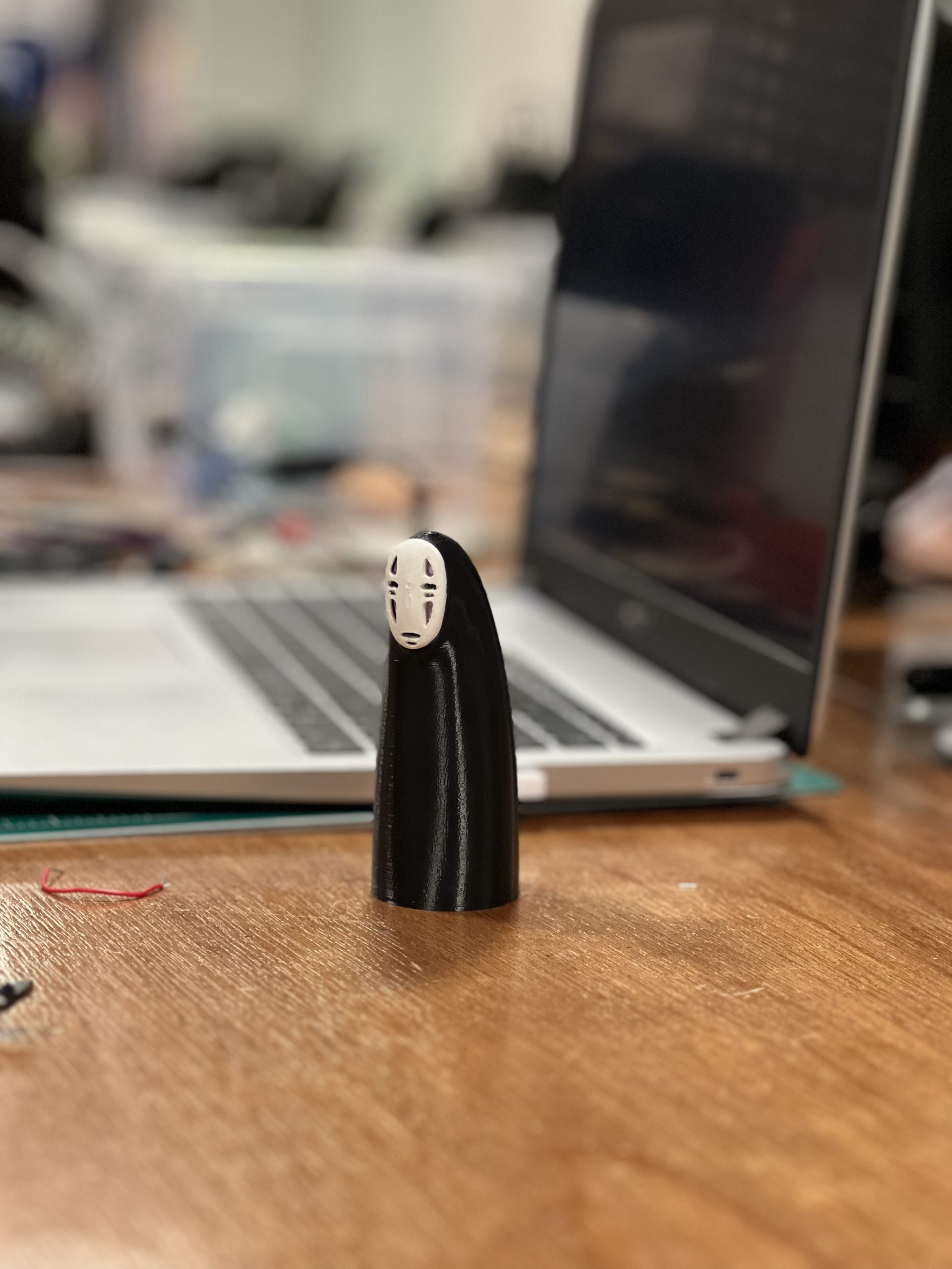
For the physical character, I was originally going to make it out of cardboard but I remembered that there’s a great website called Thingiverse with other people’s 3D model creations, which meant that I could use it as well. I did have some minor issues with printing the mask, since it didn’t completely finish printing or it wouldn’t print at all, but I figured out that it was because I tried combining the two files into one print. Other than that, 3D printing was straightforward.
Finally for the case, I decided to laser cut it, but I realized I made it too small which made it difficult to fix the circuit. That’s also probably why I didn’t realized it was the wire that broke and caused the distance sensor to not work anymore. I also took a few tried to adjust the height for the holes for the distance sensor and I wish I made the holes a little smaller because the sensor kept sliding out.
Code: Arduino, p5.js, and Communication Between
p5.js Code
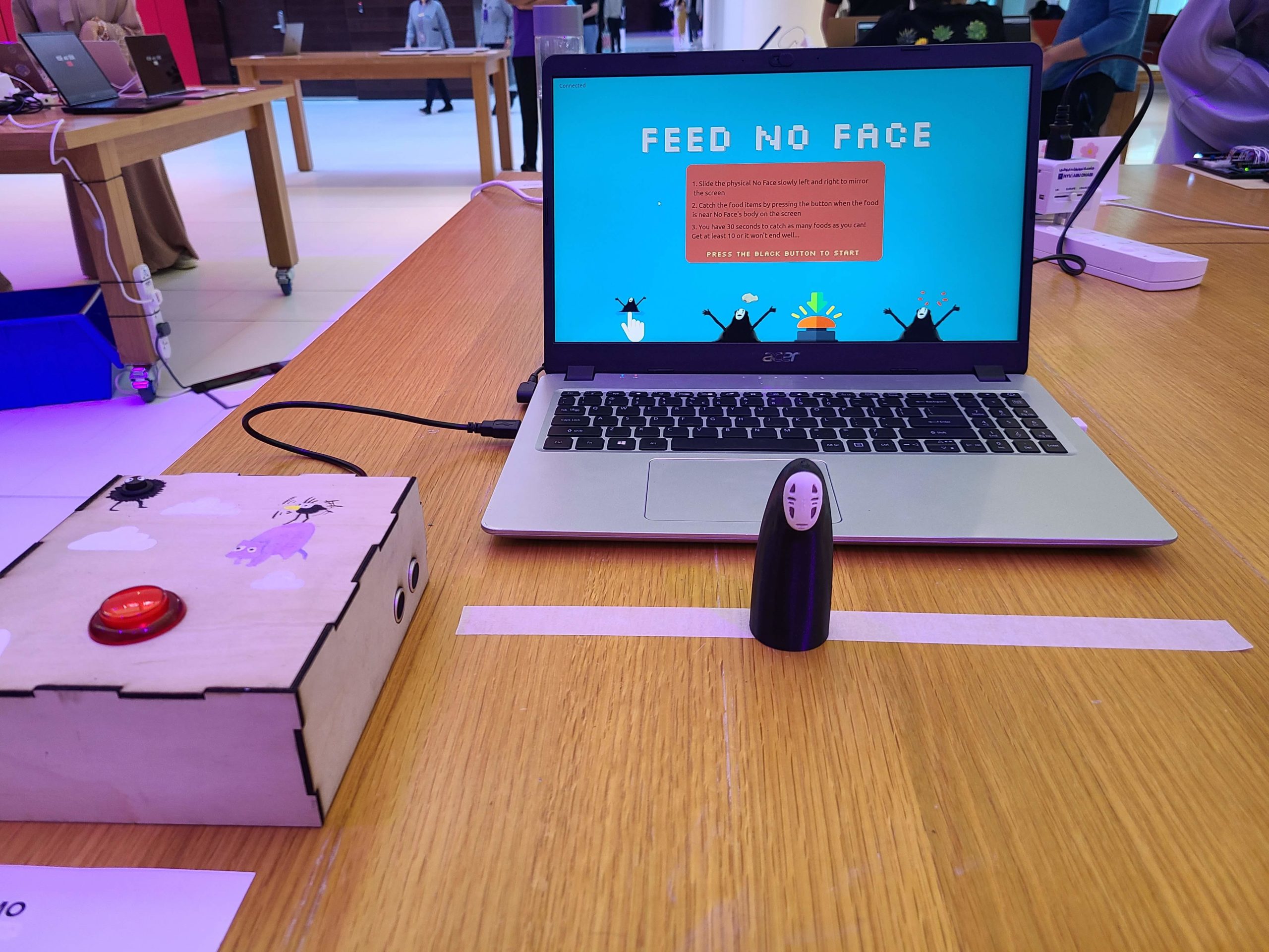
Since I was using my midterm project for the final project, there wasn’t much to do on the p5 sketch side. The only edits I made were changing the game mechanism (catch the food) and the concept of the game. Instead of dying after missing one food item, the player has 30 seconds to catch at least 10 foods or they will get a “bad” ending. Therefore, I had to implement two ending screens and a timer.
function countdown() {
  if (frameCount % 60 == 0 && timer > 0) {
    timer--;
  }
  fill("red");
  text(timer, 30, 80);

  if (timer == 0) {
    gameState = "end";
    timer = 30;
  }
}
The timer was pretty straightforward: since the there are 60 frames for every second, I used the modulus to get the remainder and decrement timer. When I first used this and restarted the game, it went directly to the end page and I realized that I forgot to reset the timer to 30 seconds again.
I also had to experiment with the distance between the character and the food, since the catch is no longer using the mouse position.
Arduino Code
As for the Arduino side, the trickiest part was definitely getting the distance sensor to have smoother readings (thanks professor for helping with that!). I looked at a bunch of examples, but the one that worked for me was using the average and discarded any readings outside the range of 5-40 cm. This worked pretty well compared to when there was no smoothing, but there were some times where the distance sensor would get a readings that aren’t accurate, for example it would go from 15 to 20.
total = total - readings[readIndex];
  readings[readIndex] = distance;
  total = total + readings[readIndex];
  readIndex = readIndex + 1;

  if (readIndex >= numReadings) {
    readIndex = 0;
  }

  average = total / numReadings;

  if (average >= 5 && average <= 42) {
    //    Serial.print("Distance: ");
    //    Serial.println(average);
    //    Serial.println(" cm");
    currentAverage = average;
    delay(1);
  }
The communication between Arduino and p5.js was also kind of difficult, since the serial print sometimes didn’t work. For example, p5 wouldn’t get the data but that’s because I forgot to do println for the last one.
Conclusion: What I’m Proud Of and Future Improvements
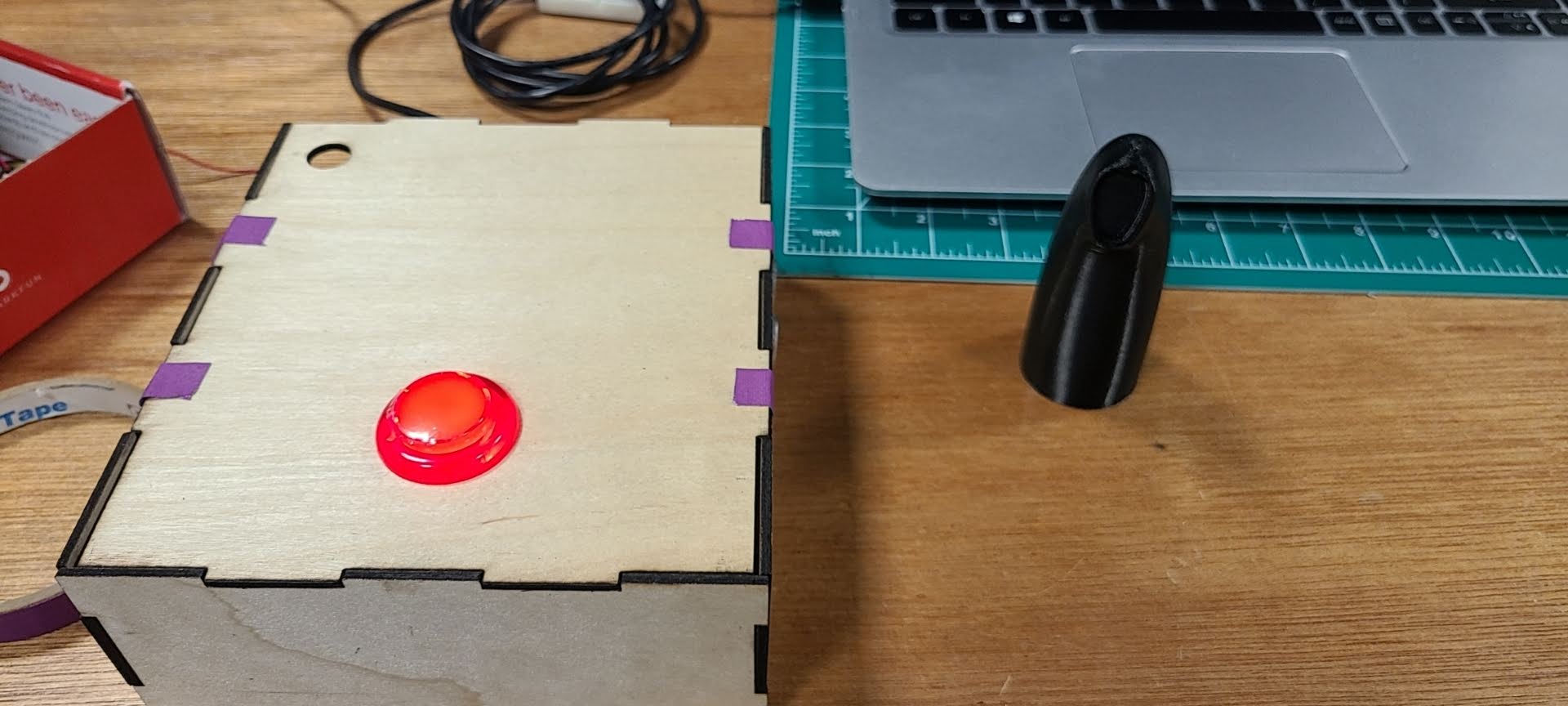
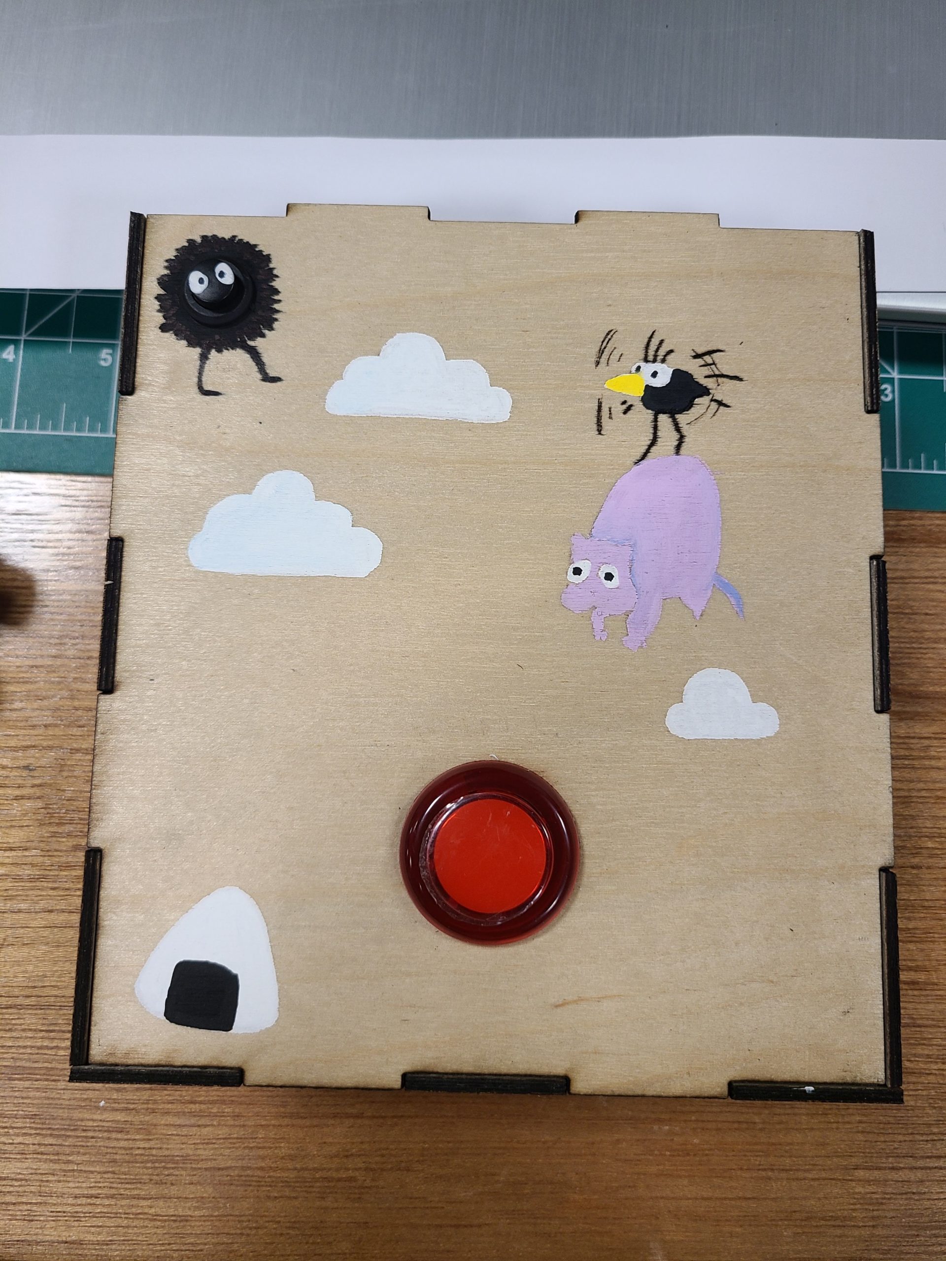
Some improvements are definitely needed. As I was showing my project, a lot of people tended to press the black button to catch the food rather than the red button. Also, sometimes the character would overlap with the food and the player would press the button, but the food wouldn’t be eaten, so I would need to continue experimenting with the distance. For the physical character, some people wouldn’t really slide it across the line, so in the future I would maybe have to create a platform with the line concave in so you could only move it in that space.
Overall, I’m really happy with how my project turned out! I wish I got more pictures of people playing the game during the showcase, but I will remember it for as long as I can. It’s so fun to see how people interacted with my game and hear the things they had to say about it. While I did have a lot of ups and downs, I’m proud of how the physical components actually turned out. I was really trying to avoid soldering, but for the sake of a good user experience I overcame that and soldering is actually kind of fun. I really enjoyed focusing on the physical aspect of my project and spending less time with the coding aspect.
Thank you for the great semester and amazing first IM showcase! Thank you so much for having me this semester and I hope to come back some day :’)) Shukran!!
Feed No Face 2.0: User Testing
I did a few user tests throughout the making of my project, but unfortunately I only have one video.
During the user testing process, I noticed that some people were confused where to move the physical character. So for my final design, I decided to add a line to guide the user where to move the character. Additionally, since I tested it before smoothing the distance sensor, people were confused by the movement of the character. Additionally, some people thought that by moving the character to the position of the food item, it will automatically eat it. So I will need to either use a bigger button (which will be a better user experience) or make the instructions more clear.
Here is one video that I took of the user testing:
(At some point I made my friends test it so much that they were basically a master at the game)
Final – Arduino of Time
Where has the time gone? The semester is nearly over, and Christmas so close. The incomprehensible specter of 2023 peeks around the corner, and I again lament the graying of memories. Yet there is a gift that has been granted unto humanity that can color in even the most ashen of memories: music. For they say that music is the vessel of memory, and memory the muse of music.
Concept & Description
The original concept—an Arduino-powered musical instrument that users can physically interact with to play songs that activate certain effects in p5js—has fortunately withstood the tides of reality! I was also able to write up an overarching mini-narrative of sorts that serves as a framing device that ties the project together and allows for the user to have a more immersive experience.
Explained at the beginning of the p5js sketch before the main game, the premise of the project is that the user plays as an amnesiac who recovers pieces of their memory through 6 songs that are tied to certain memories and emotions of the past. The user is then presented with a list of six songs, with each one having a combination of buttons/notes—playing a song correctly on the Arduino instrument triggers an according scene of remembrance, which is represented by a short video of said memory being played together with a text box.
The project is heavily inspired by the Legend of Zelda video game series, owing to it not just the initial inspiration but also much of the assets. All 6 songs are actual songs from Legend of Zelda: Ocarina of Time, and the aesthetic direction + images and videos are from Legend of Zelda: Breath of the Wild.
Implementation & Highlights
Building upon the progress made in the last post—in which I assembled and coded the Arduino instrument, with the value corresponding to the pressed button/played note being sent to p5js—the next main step was to work on writing code in p5js that 1) gathers and holds on to the data from Arduino and 2) checks if the combination of said incoming data corresponds to one of the six songs 3) plays a number of effects corresponding to the song that has been played (if there is any). The following block of code is the method I used to achieve the first part of this step:
//Method for Collecting Arduino Data//

//Make Array to Gather Notes
const notesArray = [];

function readSerial(data) {
  ////////////////////////////////////
  /////  READ FROM ARDUINO HERE  /////
  ////////////////////////////////////
// Make sure there is actually a message
  if (data != null) {
    let fromArduino = data;
//Reset Array If It's Full (6 Notes)
    if (notesNum >= 6){
      for (i = 0; i < notesNum; i++){
        notesArray.pop();
      }
    }
//Add Played Note to the Array
    notesArray.push(data);
  }
}
As each song is an arrangement of six notes, the array needs to be able to hold onto the notes until it reaches a total of six. If a note is played after the sixth has been recorded, the array is reset to make way for a new combination. When an array is full, the second part of the step is carried out through the following code:
//Song is Stated as Array
const stormsSong = [0, 1, 4, 0, 1, 4];

//Function Used to Compare User Input to Songs
function songCheck(s1, s2){
  return s1.toString() == s2.toString();
}

//The Code Below is in Draw()
//Example: If Song is Played, Effects Activate
if ((songCheck(notesArray, timeSong)) == true){
 if (songPlaying() == false){
 //Audio File Played
  timeAudio.play();
 //Trigger Variable Set to True
  timeTrigger = true;
 }
}
//True Trigger Variable Activates Function Containing Effects
if (timeTrigger == true){
 timeMemory();
}
The function songCheck() uses the .toString() method to convert two chosen arrays into two string objects, which it then uses to compare and return whether the two are the same. As demonstrated in the example, an if() loop containing this function is used to compare notesArray with one of the six preexisting songs, which are also arrays (in this case, timeSong, an array for the Song of Time)—and if the song played on the Arduino instrument matches the song, a set of effects corresponding to the song are played.
A little explanation on the “effects”: playing each tune triggers an audio file from Ocarina of Time of the in-game ocarina playing said tune (this is prompted by the timeAudio.play() line of code), a video or gif of a scene from Breath of the Wild that corresponds with the song (which represents a memory), and a text box above it that contains a short, sentimentally written passage. Playing the Song of Time results in a trigger variable named timeTrigger being set to true, which in turn activates a function named timeMemory that contains the code for the video and text:
//Function Containing Video and Text for Song of Time
function timeMemory(){
//Video is Mapped to Image and Played
  let timeImg = timeVid.get();
  image(timeImg, 0, 0, 960, 540);
  timeVid.play();
//Make Text Box
  tint(255, 150);
  image(memoryBG, 40, 308, 880, 182);
  noTint();
//Write Text; TypeWriter Effect
  fill(185, 159, 102);
  textSize(40);
  let currentString = timeString.substring(0, currentCharacter);
  push();
  text(currentString, pageMargin + 10, 313, width - pageMargin*2, height - pageMargin);
  pop();
  currentCharacter += random(0.3, 0.5);
}
Thus is the general pattern for all 6 of the songs and the overall gameplay loop—each song has an array containing the notes; the tune last played by the user on the Arduino instrument is checked against each song; if there is a match, the effects bound to the song are played; after the song and video has played once, the screen returns back to the scene that shows the songlist; users can then play another song again and see its effects.
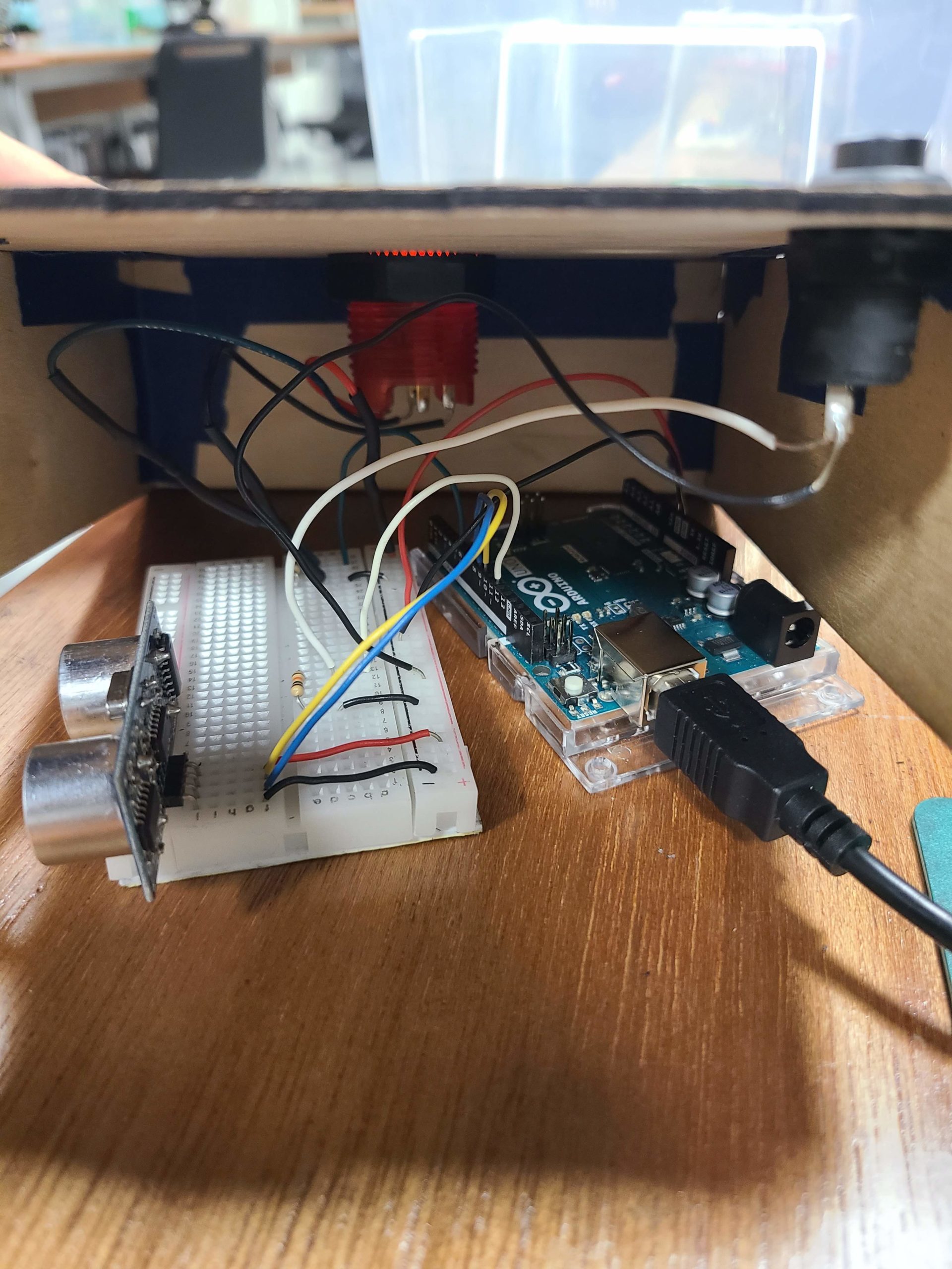
For the physical part of the project, I decided to make a nifty box of a controller-instrument with buttons and a speaker that are connected to the Arduino housed within. With help from the Lab Assistants, I was fortunate enough to be able to use the laser cutter in the IM Lab to acquire six wooden panels (the top panel having five circular holes for the buttons and one rectangular hole for the speaker, and the side panel on the right having a little hole through which the USB cable runs) that I taped together to make a rectangular prism.
One major step that I was worried about was soldering wires onto the big buttons that I chose to use (they’re so much more satisfying to press than the little ones that come in the kit). Despite having watched Professor Shiloh give a clear demonstration in class, I was nervous about trying my own hand at it. After watching a few tutorials as a refresher, I booted on the soldering station and clenched the iron in my hand—and to my surprise, it came rather easily! By the time I was soldering the wires onto the fifth and last button, I felt that I had gotten the hang of it and was somewhat successful at making the drops look nice and neat.
With the buttons all wired up and the wooden box complete, I was ready to assemble my controller-instrument. The original circuit looked like this:
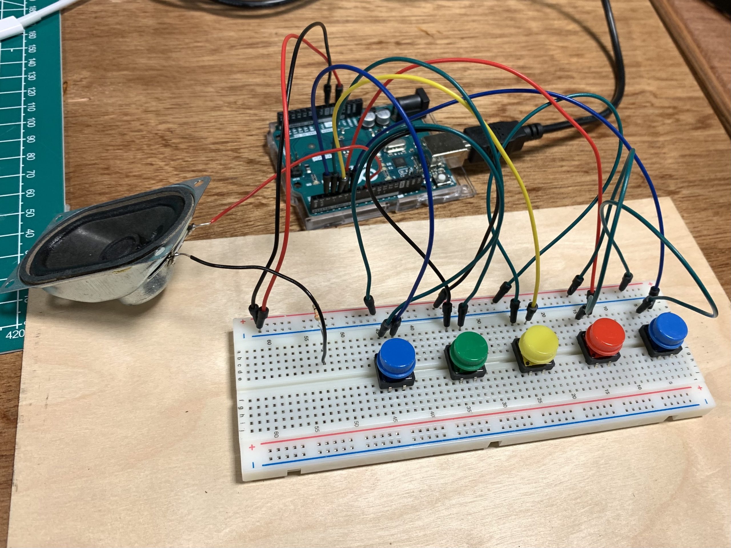
Placing the Arduino and breadboard inside the box, I carefully deconstructed the parts of the circuit that needed to be adjusted and hooked the buttons to the breadboard one by one…and voila!
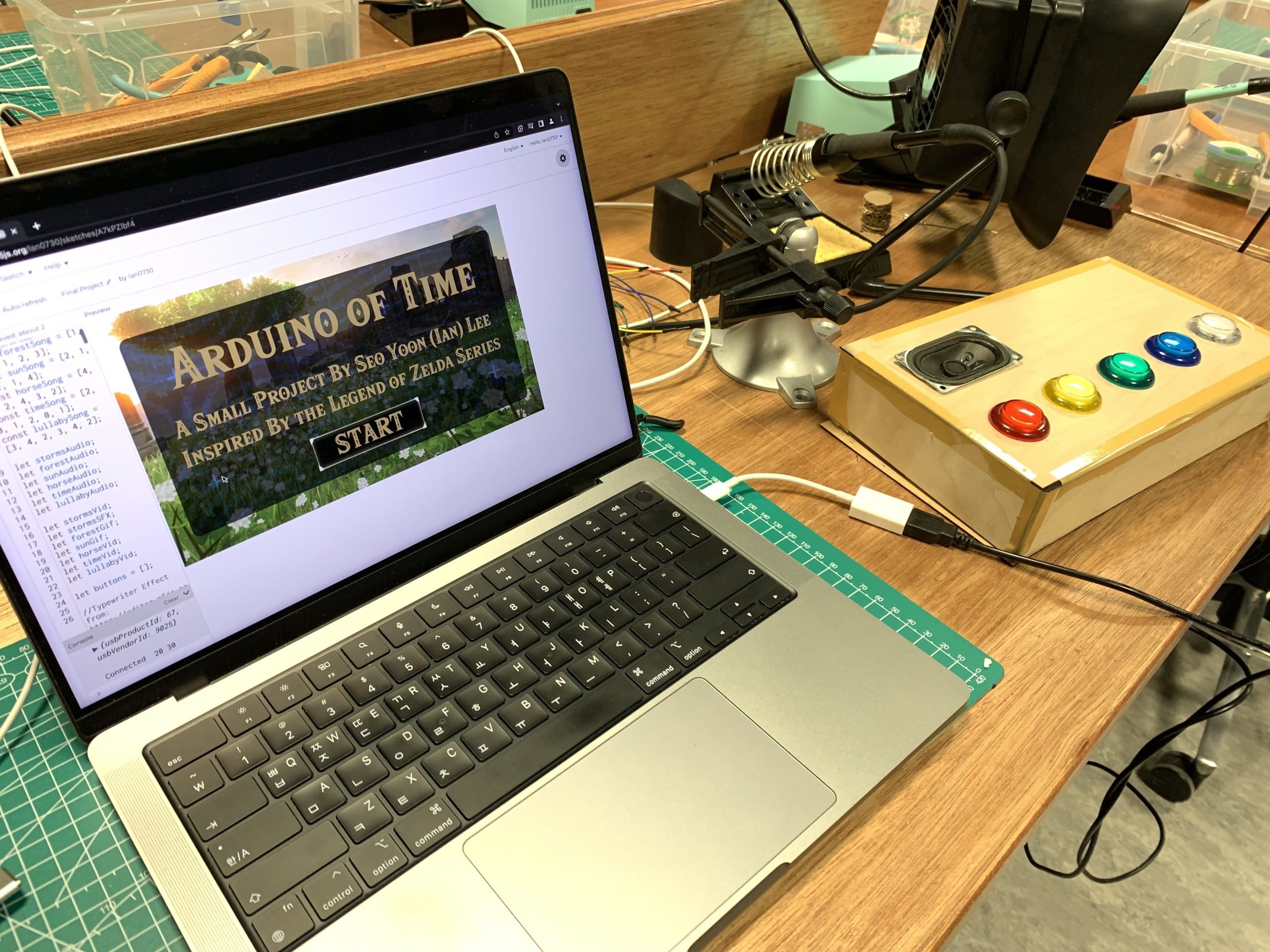
The fabled Arduino of Time.
Video Demonstration
Reflections
It’s been an amazing journey, and I’m very proud 0f what I was able to achieve for this final project! I’ve said it time and time again on this blog, but it really is a wondrous experience to fish an idea out of your mind, build upon it, and create something palpable. This course has not only taught me the basics of p5js and Arduino, but also inducted me into the realm of IM thinking—a space that encourages one to act upon creative ideas and engage with them in meaningful ways. And so the semester comes to a close…but I will continue to hold on to what I have learned.