Week 10 – Reading Reflection

Bret Victor’s “A Brief Rant on the Future of Interaction Design” reads less like a complaint and more like a plea for imagination. His frustration with “pictures under glass” isn’t really about touchscreens rather about how easily we mistake convenience for progress. Victor’s argument that our hands are not just pointers but thinking tools is relatable. I’d never thought of a touchscreen as “numb,” but he’s right: sliding a finger across glass is nothing like twisting, folding, or shaping an object. He’s asking designers to respect the body’s intelligence, the millions of years of evolution that made us good at feeling, gripping, and sensing the world. I agree with him almost entirely. What unsettles me is how quickly we’ve accepted numbness as normal. We’ve trained ourselves to think that friction is a flaw when it comes to UX.

The Responses piece adds an interesting layer of humility. Victor doesn’t pretend to have the solution. He admits he was ranting, not designing one. Still, his answers to critics are telling. He pushes back against gimmicks like voice control and “waving your hands in the air,” arguing that real interaction should involve the whole body and the tactile richness of touch. I found myself nodding at his line about computers needing to adapt to our bodies, not the other way around. That’s such a simple reversal, yet it cuts right through decades of design laziness. When he compares touchscreen culture to “restricting all literature to Dr. Seuss’s vocabulary,” it’s funny, but it also nails the deeper loss: we’re settling for tools built for children, not adults.

If there’s one thing I’d question, it’s Victor’s nostalgia for physicality. I agree that touch and movement matter, but I also think the human imagination adapts. The digital world is training new forms of dexterity which are mostly mental than physical. Coding, multitasking, navigating layered interfaces – these, too, are forms of “touch,” just less visible. Maybe the future of interaction design isn’t about replacing glass with holographic clay, but about balancing sensory depth with cognitive range. Victor’s rant reminds me that design should evolve with both the hand and the mind.

Week 10 – A DIY Musical Instrument (The Ultrasonic Air Piano)

Concept:

The idea behind my instrument was to create a hands-free musical device that transforms invisible gestures into sound. My goal was to design something playful yet technical; a device that reacts to both motion and touch. By combining distance and pressure, the instrument invites intuitive exploration: the closer your hand gets, the higher the note, while pressing the sensor triggers the sound. It merges tactile interaction with sound, making music a physical experience.


Method & Materials:

This project was my first time working with two types of sensors on the Arduino Uno:

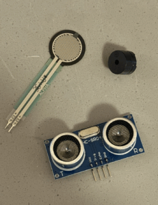
  • Analog Sensor: Ultrasonic sensor (HC-SR04) to measure distance.
  • Digital Switch: Force Sensitive Resistor (FSR) to detect pressure.
  • Output: Piezo buzzer to produce sound.

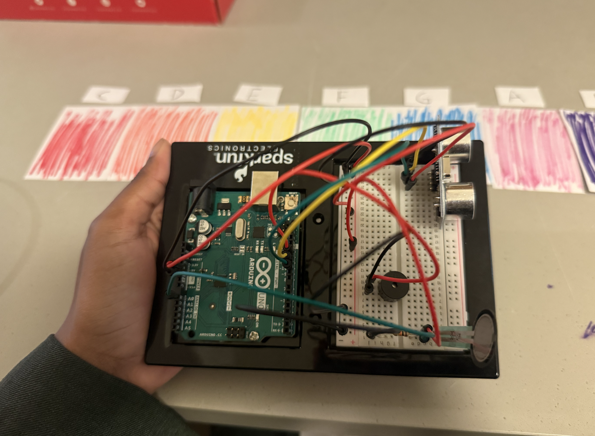
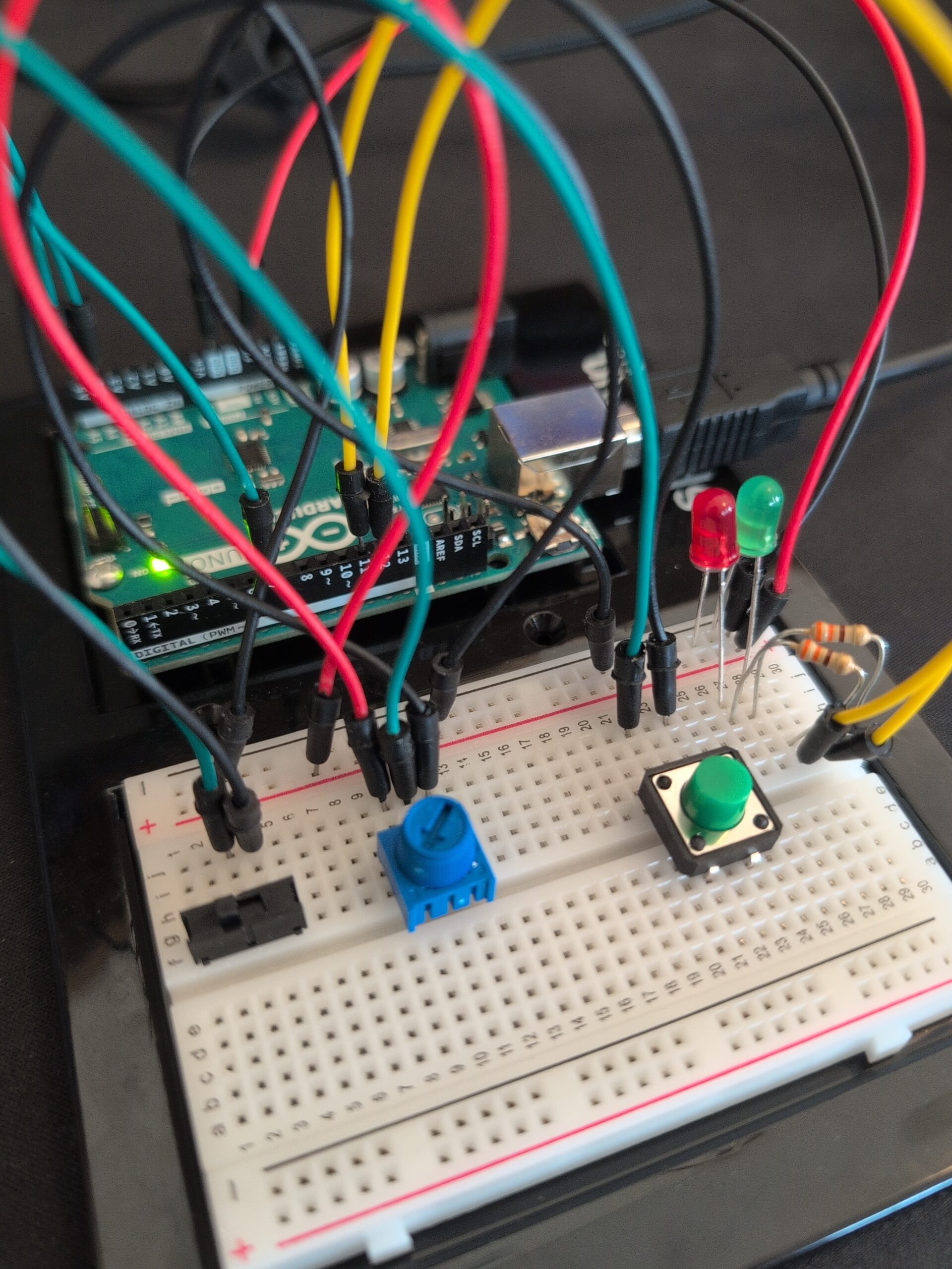
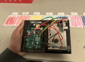
I connected the ultrasonic sensor to pins 10 (trig) and 11 (echo), the FSR to analog pin A0, and the buzzer to pin 12.
Each note from the C major scale (C–D–E–F–G–A–B) was assigned to a specific distance range, coded in an array:

int notes[7] = {261, 294, 329, 349, 392, 440, 494};

The system reads distance in real time:

  • When the FSR is pressed and your hand is between 0–50 cm of the sensor, the buzzer plays a tone corresponding to that range.
  • If no pressure is detected or the hand moves out of range, the sound stops.

Process:

At first, it took time to understand how analog vs. digital inputs work and how to read them simultaneously. I researched how to use pulseIn() for the ultrasonic sensor and experimented with mapping values using the map() function.
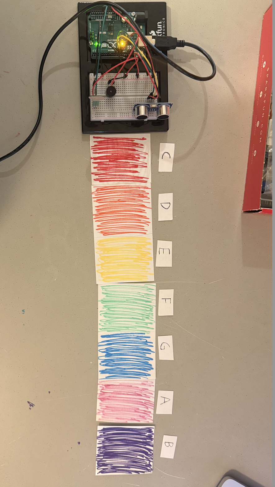
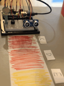
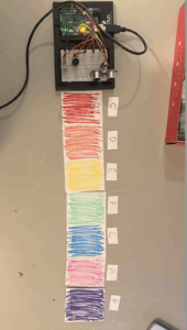
To visualize the notes, I placed colored paper strips at different distances  (each representing one note of the scale)

Throughout the process, I learned:

  • The importance of wiring correctly (e.g., ensuring the FSR forms a voltage divider).
  • How combining two sensors can create more expressive interaction.
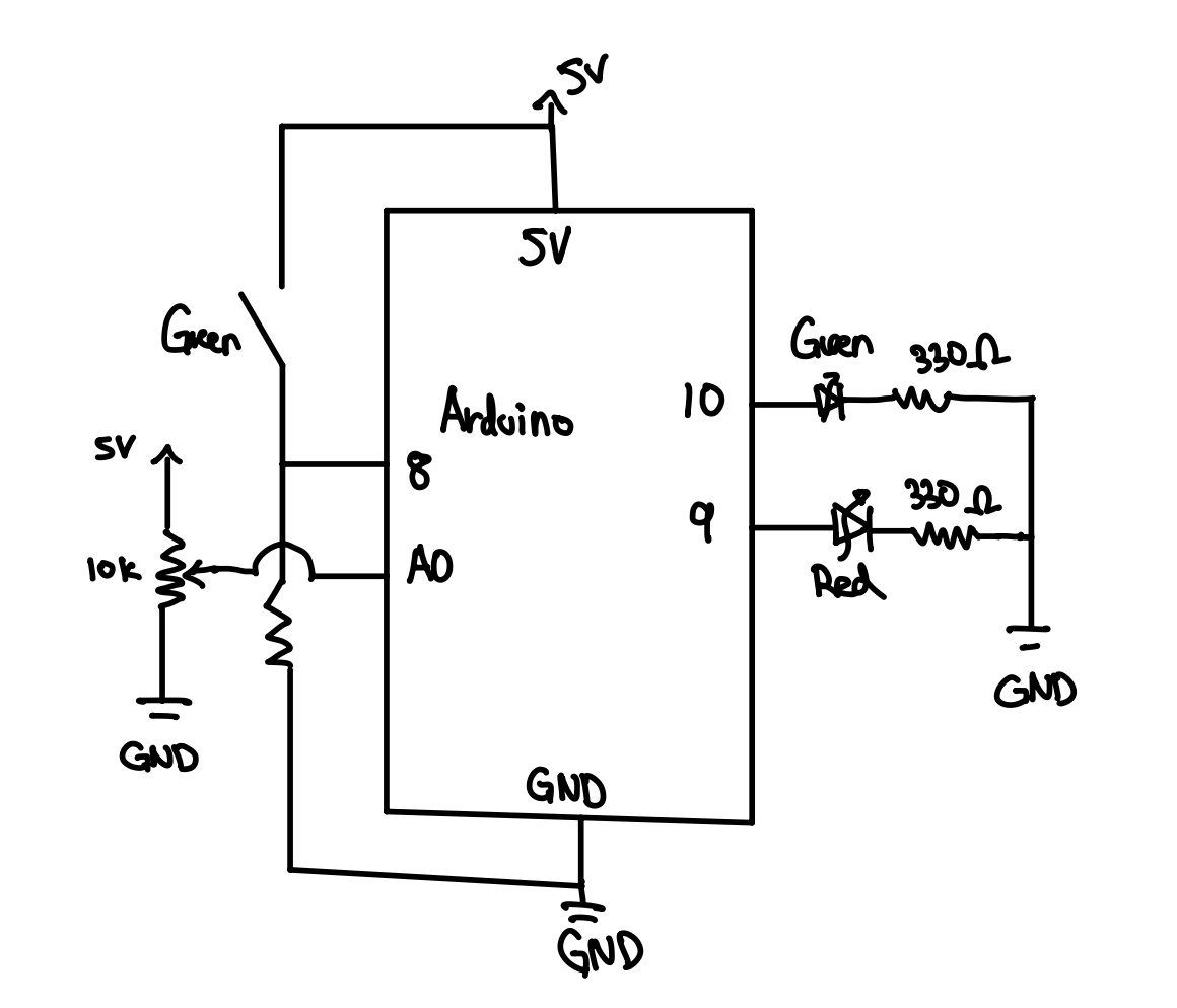
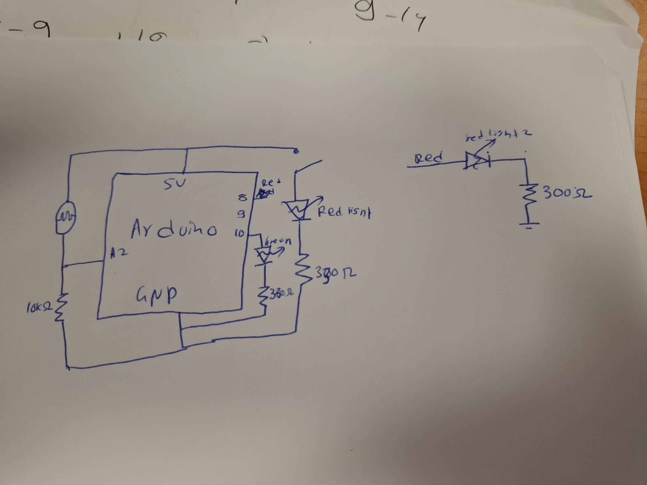
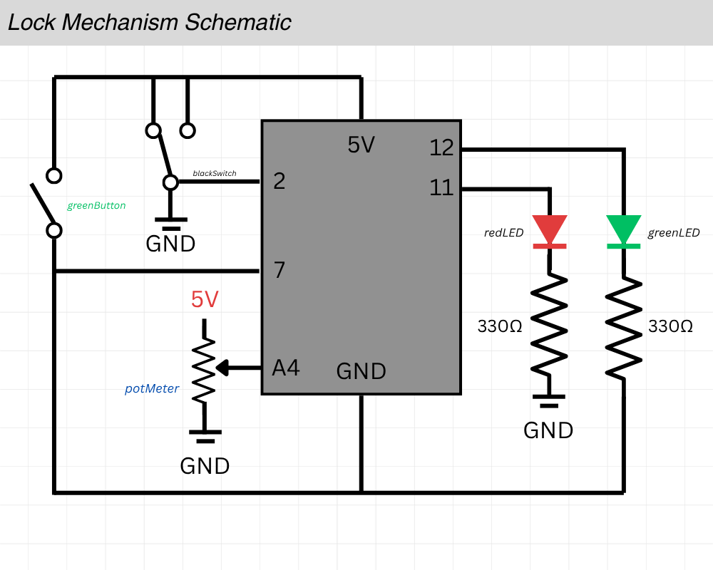
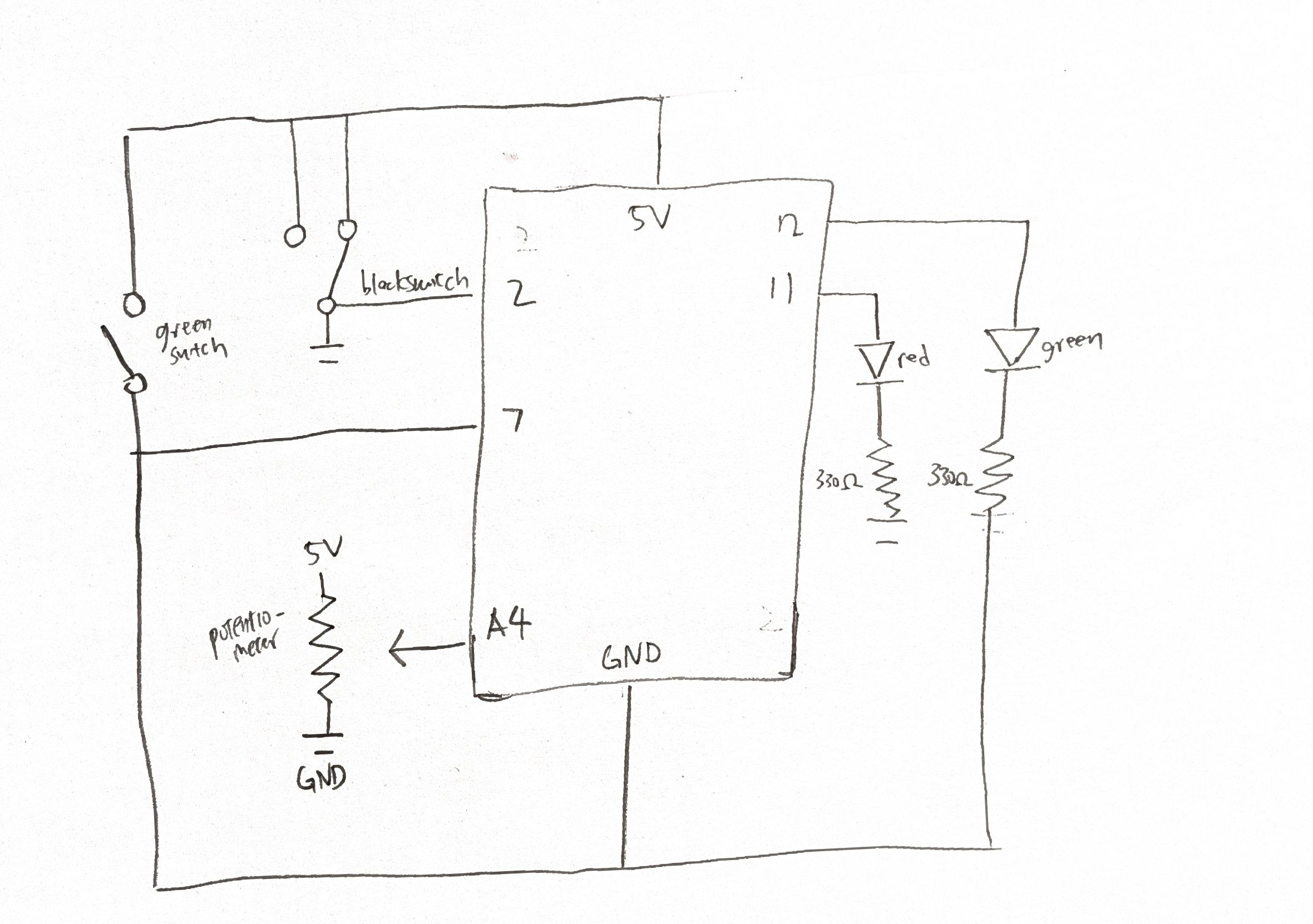
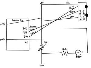
Schematic:

Code:

This combines input from two sensors, an ultrasonic sensor and a force-sensitive resistor (FSR) to generate musical notes through a piezo buzzer. The ultrasonic sensor continuously measures the distance of my hand, while the FSR detects when pressure is applied. When both conditions are met (hand within 50 cm and FSR pressed), the code maps the distance value to a specific note in the C major scale (C, D, E, F, G, A, B). Each distance range corresponds to a different pitch, allowing me to “play” melodies in the air. The code I’m most proud of is the single line that transforms the project from a simple sensor experiment into a musical instrument. It defines the C major scale, turning numerical frequency values into recognizable notes. I love that such a short line of code gives the device its expressive character, it bridges logic and creativity, translating distance data into melody. It’s the heart of the project, where sound and interaction truly come together.

// --- Define musical notes (C major scale) ---
int notes[7] = {261, 294, 329, 349, 392, 440, 494}; // C D E F G A B
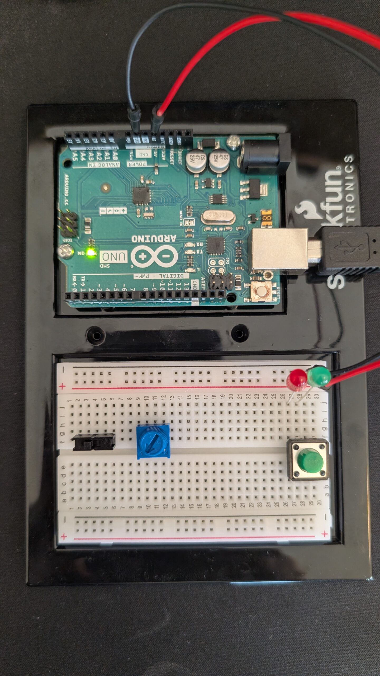
Result:

The final prototype acts like an invisible piano: you play by waving your hand in front of the sensor and pressing lightly on the FSR. Each distance triggers a different musical note. The colored papers made it easier to perform intentionally and visually mark pitch changes.

In the demonstration video, the tones respond smoothly to my gestures, transforming simple components into an expressive interface.

Challenges:

One of the main challenges I faced was understanding how each pin on the ultrasonic sensor worked. At first, I didn’t realize that every pin had a specific purpose, like trig for sending signals and echo for receiving them, so it took me a while to fully grasp how data was actually being measured. I also struggled with wiring the circuit, often making small mistakes that stopped the whole setup from working. Drawing out the schematic was another time-consuming part since there were many components to connect and label correctly. Finally, the coding process was challenging because it was my first time using several of these elements, and I had to learn through trial and error how to make the sensors and buzzer communicate smoothly.

Inspiration + Tools thats helped me:

https://projecthub.arduino.cc/theriveroars/simple-hand-controlled-instrument-372bfc

https://learn.adafruit.com/force-sensitive-resistor-fsr/using-an-fsr

Reflection:

This project taught me how code, sensors, and sound can merge into interactive art. The challenge was balancing sensitivity: sometimes the ultrasonic readings fluctuated, and it took some fine tuning. But once it worked, it felt rewarding to hear the instrument. It also made me realize how music can be built from logic, how creative coding allows emotional expression through electronics. I see this as the beginning of exploring computational instruments that combine art and technology.

Week 9 – Two-Degree Safety

My Concept

I decided to build a “two-degree safety guardrail.” The logic is based on two separate actions:

  1. Idle State: A red LED is ON (digital HIGH).
  2. “Armed” State: A button is pressed. This turns the red LED OFF (digital LOW).
  3. “Active” State: While the button is held, a FSR (force-sensing resistor) is pressed, which controls the brightness of a green LED (my analog output).

Challenge

My challenge was getting the red LED to be ON by default and turn OFF only when the button was pressed. I tried to build a hardware-only pull-up or bypass circuit for this but struggled to get it working reliably on the breadboard.

So, I shifted that logic into Arduino code adapted from a template in the IDE.

// constants won't change. They're used here to set pin numbers:
const int buttonPin = 2;  // the number of the pushbutton pin
const int ledPin = 13;    // the number of the LED pin

// variables will change:
int buttonState = 0;  // variable for reading the pushbutton status

void setup() {
  // initialize the LED pin as an output:
  pinMode(ledPin, OUTPUT);
  // initialize the pushbutton pin as an input:
  pinMode(buttonPin, INPUT);
}

void loop() {
  // read the state of the pushbutton value:
  buttonState = digitalRead(buttonPin);

  // check if the pushbutton is pressed. If it is, the buttonState is HIGH:
  if (buttonState == LOW) {
    // turn LED on:
    digitalWrite(ledPin, LOW);
  } else {
    // turn LED off:
    digitalWrite(ledPin, HIGH);
  }
}

The demo was shot with the Arduino implementation.

Schematic

However, I later figured out the pull-up logic, and was able to implement a hardware-only solution. This schematic was a result of the updated circuit.

Week 10 – Reading Response (A Brief Rant on the Future of Interaction Design)

One passage that really stayed with me from Bret Victor’s A Brief Rant on the Future of Interaction Design is his statement that screens are “pictures under glass.” That phrase hit me because it’s so ordinary yet so revealing; every day I touch my phone dozens of times, yet I never actually feel anything back. Victor’s argument that we’ve limited human interaction to tapping on cold glass made me realize how passive our so-called “interactive” technologies have become. I started thinking about how my creativity, whether sketching or coding, always feels richer when my hands are physically involved; pressing, folding, shaping. It made me question: why did we let convenience replace tactility? What would technology look like if it honored the intelligence of our hands instead of reducing them to cursors?

In the Responses section, I was fascinated by how defensive many readers became, as if Victor’s critique was anti-progress. But what I sensed in his tone was care, not nostalgia; a desire to expand our sense of what interaction can mean. This really reminded me of  Refik Anadol’s Machine Hallucinations, a piece I’m analyzing for another course, where data transforms into movement, color, and emotion. Anadol’s work feels like the future Victor imagines: one where technology engages the body and senses, not just the eyes.

These readings challenged my old assumption that the “best” design is the smoothest and most frictionless. Victor helped me see friction as meaningful; it’s how we feel our way through the world. I now think of design less as creating perfect efficiency and more as crafting moments of connection between body, mind, and machine. The essay left me wondering whether the future of interaction design depends not on faster touchscreens, but on rediscovering touch itself; real, textured, imperfect, human touch.

Ultimately, I completely agree with Victor’s message. His critique felt refreshing, almost like a wake-up call to slow down and rethink what “innovation” actually means. I liked how he exposed the emptiness behind shiny new interfaces and instead celebrated the physical, human side of design. Even though his tone was mainly critical, I didn’t find it negative; I found it hopeful. It made me appreciate the kind of design that makes people feel connected, not just technologically advanced.

Week 9 – Reading Response

Interactive art should be designed as a conversation (or workshop seminar) instead of a speech. The clearest takeaway from the two pieces is that affordances and arrangements matter more than artist statements. If the system communicates its possibilities through handles, hints, and constraints, the audience can complete the work through action. When artists over-script, they collapse the range of possible meanings and behaviors into one narrow path.

Physical computing’s “greatest hits” list is useful because it exposes where interaction often stalls. Video mirrors and mechanical pixels are beautiful, but they rarely push beyond “move, see response.” Gloves, floor pads, and utilty controllers introduce a structured gesture vocabulary that people already know, which shortens the learning curve. Across categories: where gesture has meaning, interaction retains depth; where mappings are shallow, novelty fades quickly.

These pieces prompt two design questions. First, what minimal cues will help a participant discover the interaction without text? Second, what state changes will keep the system from settling into a single loop? In practice, that means compositional choices, such as discrete modes, cumulative effects, and recoverable errors.

For attention sensing, presence is not engagement. Designers should think of for signals that correlate with intent, then treat them probabilistically. Use the audience’s behavior as feedback to adjust affordances, not narratives. If the work does not evolve under interaction, you likely built a display, not a performance.

Week 9 – Arduino: analog input and output

Today’s class went over some of the questions I had in mind in creating the circuit and I was able to complete the assignment.

I made a circuit that took in two inputs, green switch and potentiometer. The output is displayed with two led lights: green and red.

int greenPin = 10;    
int redPin   = 9;     
int buttonPin = 8;    
int potPin    = A0;

void setup() {
  pinMode(greenPin, OUTPUT);    //two outputs led
  pinMode(redPin, OUTPUT);
  pinMode(buttonPin, INPUT);   //Input for button 

  digitalWrite(greenPin, HIGH);   //testing if leds work
  delay(1000);
  digitalWrite(greenPin, LOW);
  digitalWrite(redPin, HIGH);   
  delay(1000);
  digitalWrite(redPin, LOW);
}

void loop() {

  int potValue = analogRead(potPin);               //reading potentialometer value
  int brightness = map(potValue, 0, 1023, 0, 255); //scaling the potentimeter from 0 to 255
  int buttonState = digitalRead(buttonPin);        //when pressed it is set as high

  if (buttonState == HIGH) {      //if button is pressed, turn both lights off
    analogWrite(greenPin, 0); 
    analogWrite(redPin, 0);
  } else {                          //if not pressed, light's brightness is controlled by pot.
    analogWrite(greenPin, brightness);
    analogWrite(redPin, brightness);
  }
}

Basically, by default, the two led light’s brightness is controlled by the potentiometer. When I turn the potentiometer to max voltage, the led lights light up with maximum brightness. Otherwise, if I turn the potentiometer to 0, it means that the voltage becomes 0, hence showing no light.

Another input is the green switch and I made it so that when the button stage is high, meaning that when its pressed, the output becomes , turning the lights off.

This is the sample video:


This is the hand-drawn schematic, that we practiced in class today. Re-drawing it definitely helped.

Schematic Week 9 Handrawn

Week 9: Reading Response


Physical Computing’s Greatest hits and misses

When I read Physical Computing’s Greatest Hits (and Misses) by Tom Igoe, I found it fascinating how creativity often repeats itself, not out of laziness, but because some ideas are simply too human to let go of. Whether it’s waving your hand to make music like a theremin, or building dancing floor pads inspired by Dance Dance Revolution, these projects remind me that interaction is a language our bodies already know.

Igoe’s writing made me realize that physical computing isn’t just about wiring sensors or programming microcontrollers. It’s about finding meaning in movement and connection. His examples like gloves that make drum sounds or video mirrors that reflect your gestures  all blur the line between play and design. I like how he admits that some of these projects are “pretty but shallow.” It’s honest. It’s easy to get lost in flashing LEDs and forget to ask: what experience am I creating for the user?

The part that stayed with me most was his reminder that originality doesn’t mean doing something no one’s ever done before  it means doing something familiar in a new way. That’s comforting. As someone who’s just learning, I often feel like my ideas are too simple or already “done.” But after reading this, I see that even a basic project, a light sensor or a glove, can become unique if I bring my own perspective, story, or purpose to it.

Making Interactive Art: Set the Stage, Then Shut Up and Listen

When I was reading Tom Igoe’s Making Interactive Art: Set the Stage, Then Shut Up and Listen, I was struck by how simple yet challenging his message was. He tells artists and creators to stop explaining their own work  to resist the urge to direct, interpret, or control what others should feel. It’s funny how that sounds easy, but for anyone who’s ever made something personal, it’s actually the hardest thing to do. We want to be understood. We want people to “get it.”

Igoe reminds us that interactive art isn’t about showing, it’s about inviting. The artist’s job is not to tell a story, but to create a space where others can find their own. When he says, “Once you’ve built it, shut up,” it hit me like a creative reality check. In most traditional art forms painting, photography, sculpture  the work speaks through form and color. But with interactive art, the audience literally completes the piece through their movement, curiosity, and touch. That’s terrifying and beautiful at the same time.

I also loved how Igoe compares designing interaction to directing actors. You can’t tell an actor how to feel; you just set the stage, give them a prop, and trust that they’ll find emotion in the act itself. That idea applies perfectly to physical computing and interactive design. The best projects don’t just respond to people  they encourage discovery. They leave space for mistakes, surprises, and personal interpretation.

Reading this made me think differently about my own work. I realized that in some of my projects, I’ve tried to control the experience too tightly giving too many instructions or forcing a specific reaction. But now, I see that a good interactive project is a conversation, not a lecture. It listens as much as it speaks.

Week 9: Smart Pedestrian Light System

Concept:

In my home town, we don’t usually have automatic traffic lights for pedestrian (zebra) crossings. When I came to the UAE, I found it really interesting that many crossings have a touch-sensitive button on the pole, when a pedestrian presses it, the system detects the request and changes the traffic light to red for vehicles, allowing people to cross safely.

263 Abu Dhabi Road Signs Stock Video Footage - 4K and HD Video Clips | Shutterstock

I wanted to mimic that concept using simple electronic components. In my prototype, a light sensor (LDR) acts as the pedestrian touch detector. When I place my finger over the sensor,  “green” light turns on (in my case, a blue LED, since my green ones were damaged), signaling that a pedestrian wants to cross. When the sensor is not covered, meaning the LDR value stays above a certain threshold (around 400), it represents that no one is waiting to cross, so the “red” light for pedestrians remains on.

Additionally, I included a digital switch that simulates a traffic officer controlling the lights manually. Whey they clicked the red button, red light turns on and force they vehicle to stop.

Video:


Code:

const int LDR= A2;
const int LDR_LED=10;
const int red_LDR=8;
void setup() {
  // put your setup code here, to run once:

  Serial.begin(9600);
}

void loop() {
  // put your main code here, to run repeatedly:
  int value= analogRead(LDR);
  Serial.println(value);
   
  if(value<=500){
    digitalWrite(LDR_LED,HIGH);
    Serial.println("yes");
   
    digitalWrite(red_LDR,LOW);
   
  }
  else{
    digitalWrite(LDR_LED,LOW);
    digitalWrite(red_LDR,HIGH);
  }
  
}


Schematics:

Week 9 assignment

For this assignment, I decided to use the potentiometer and the button. I wanted the potentiometer to control how bright the RGB light is and use the switch button for 2 purposes, to change the general colour of the RGB but to also start and stop the blinking of the red alarm LED I used.

I had the code use 4 different colours but have this also a factor on how many blinks occur with the LED light.

I had the switch button be used as a way to have the red LED on or off.

To be honest, I used the Claude Sonnet 4..5 model to give me ideas on how I can make the whole system more interesting / creative. That is how the idea of having the number of pings be dependent on the colour came from.

this is the code I used

// PIN location
const int POT_PIN = A0;           // Potentiometer
const int BUTTON_PIN = 2;         // Push button 
const int RGB_RED_PIN = 9;        
const int RGB_GREEN_PIN = 10;     
const int RGB_BLUE_PIN = 11;      
const int MODE_LED_PIN = 13;      // Ree LED 

int potValue = 0;                 
int brightness = 0;               
bool buttonState = false;         
bool lastButtonState = false;     
int colorMode = 0;               
unsigned long previousMillis = 0; //  non-blocking blink timing
const long blinkInterval = 150;   // blink interval for mode indicator
bool modeLedState = false;        

const char* modeNames[] = {"White", "Red", "Green", "Blue"};

void setup() {
  Serial.begin(9600);
  
  // set pins
  pinMode(POT_PIN, INPUT);
  pinMode(BUTTON_PIN, INPUT);
  pinMode(RGB_RED_PIN, OUTPUT);
  pinMode(RGB_GREEN_PIN, OUTPUT);
  pinMode(RGB_BLUE_PIN, OUTPUT);
  pinMode(MODE_LED_PIN, OUTPUT);
  
  // initialise LEDs as off
  analogWrite(RGB_RED_PIN, 0);
  analogWrite(RGB_GREEN_PIN, 0);
  analogWrite(RGB_BLUE_PIN, 0);
  digitalWrite(MODE_LED_PIN, LOW);
}

void loop() {
  // potentiometer read
  potValue = analogRead(POT_PIN);
  
  // map the values of the potentiometer to a brightness value
  brightness = map(potValue, 0, 1023, 0, 255);
  
  // button read
  buttonState = digitalRead(BUTTON_PIN);
  
  // when button is pressed, change the colour
  if (buttonState == HIGH && lastButtonState == LOW) {
    colorMode = (colorMode + 1) % 4;  //cycle through 0-3
    Serial.println(modeNames[colorMode]);
    delay(50);  
  }
  
  lastButtonState = buttonState;
  
  // change RGB LED based on selected colour
  switch(colorMode) {
    case 0:  //  white
      analogWrite(RGB_RED_PIN, brightness);
      analogWrite(RGB_GREEN_PIN, brightness * 0.8); 
      analogWrite(RGB_BLUE_PIN, brightness * 0.6);  
      break;
      
    case 1:  // red 
      analogWrite(RGB_RED_PIN, brightness);
      analogWrite(RGB_GREEN_PIN, 0);
      analogWrite(RGB_BLUE_PIN, 0);
      break;
      
    case 2:  // green 
      analogWrite(RGB_RED_PIN, 0);
      analogWrite(RGB_GREEN_PIN, brightness);
      analogWrite(RGB_BLUE_PIN, 0);
      break;
      
    case 3:  // blue 
      analogWrite(RGB_RED_PIN, 0);
      analogWrite(RGB_GREEN_PIN, 0);
      analogWrite(RGB_BLUE_PIN, brightness);
      break;
  }
  
  // Mode 0 = no blinks (off)
  // Mode 1 = 1 blink
  // Mode 2 = 2 blinks 
  // Mode 3 = 3 blinks
  handleModeIndicator();
  delay(10);  // Small delay for stability
}

//function to handle the 
void handleModeIndicator() {
  unsigned long currentMillis = millis();
  static int blinkCount = 0;
  static unsigned long patternStartTime = 0;
  static bool isBlinking = false;
  
  // when white, keep LED off
  if (colorMode == 0) {
    digitalWrite(MODE_LED_PIN, LOW);
    blinkCount = 0;
    isBlinking = false;
    return;
  }
  
  // new blink pattern every 2 seconds
  if (!isBlinking && (currentMillis - patternStartTime >= 2000)) {
    isBlinking = true;
    blinkCount = 0;
    patternStartTime = currentMillis;
  }
  
  // perform blinks equal to color mode number
  if (isBlinking) {
    unsigned long timeInPattern = currentMillis - patternStartTime;
    int currentBlink = timeInPattern / (blinkInterval * 2);  // *2 for on+off
    
    if (currentBlink < colorMode) {
      // still within the blink count for this mode
      unsigned long timeInBlink = timeInPattern % (blinkInterval * 2);
      
      if (timeInBlink < blinkInterval) {
        digitalWrite(MODE_LED_PIN, HIGH);  // LED on
      } else {
        digitalWrite(MODE_LED_PIN, LOW);   // LED off
      }
    } else {
      digitalWrite(MODE_LED_PIN, LOW);
      isBlinking = false;
    }
  }
}


IMG_2228


Week 9: Lock Mechanism (Analog + Digital)

I initially really struggled to come up with a concept for this week’s project. While I understood how to use analog and digital switches, I wasn’t sure how I would use them in conjunction to create something engaging and interesting. I slept on it and woke up with the idea to build off the theme of security from week 8 and make a lock mechanism using analog inputs like the potentiometer.

One of my biggest concerns was that I wasn’t sure how to draw a proper schematic so I looked online and used Tinkercad Circuits for a while but it wasn’t exactly the simple schematic drawing I wanted so I decided to save the site for future use instead.

This was the schematic I came up with. I knew I was going to mess up and have to move stuff around so I did it digitally using simple shapes and lines on canvas. I barely knew what I was doing and to be honest it made a LOT more sense to just start putting wires and pieces together on the breadboard but this schematic was how I thought it would look.

And this is how it looked physically with all the relevant pieces attached to the breadboard.

I knew the wiring would get pretty crazy as I started to connect everything so this is how I color-coded them:

    • Red: Power Source (+)
    • Black: Ground (-)
    • Green: Inputs Connections to Arduino Uno (Switch, Pot Meter, etc)
    • Yellow: Output Connections to Arduino Uno (LEDs)

On the code-side, I made sure to declare each pin I was going to use at the very top so I could quickly change it if I needed to swap stuff around.

int greenButton = 7; //button to open lock
int blackSwitch = 2; //part of the lock (the black on/off switch)
int potMeter = A4; //part of the lock (the roating blue one)

int greenLED = 12; //lock is open
int redLED = 11; //indicates lock is still locked

//LOCK COMBINATIONS
int blackSwitchANSWER = LOW;
int potMeterANSWER = 1000; //above X value to be correct

This is what the final product looked like:

I didn’t run into many bugs when coding but I did initially accidentally set the red light to always be on unless I was holding down the green button. I had to search online how I could fix this and I eventually found I could set the pinmode for the button to “INPUT_PULLUP” which was useful for inputs that otherwise would have no stable value when not pressed.

pinMode(greenButton, INPUT_PULLUP); //INPUT_PULLUP is good for buttons that automatically spring back uppinMode(blackSwitch, INPUT_PULLUP);
pinMode(potMeter, INPUT);

pinMode(greenLED, OUTPUT);
pinMode(redLED, OUTPUT);

I did have a physical difficulty where I was testing different kinds of inputs with the switch and the potentiometer and forgot what the correct combination actually was– and with no way to know if the green light was even going to turn on when it WAS correct. Thankfully a minute of trial and error and making sure the code side of things was correct got me to return to the original combination, but that could’ve been pretty annoying if the lock was any more complicated.

When it came to the LED light responses. I originally had the appropriate light turn on for 2 seconds and then turn off. I felt like this didn’t feel quite right so I made a creative decision to flash the appropriate light as feedback instead; I did this by creating a for loop that would flash the light 5 times with a small delay. This felt a LOT more responsive than the brief moment that the light would turn on previously. Below is the full if-statement that checked whether the confirm button, the green one, was pressed.

if (greenButtonState == LOW) {  
  if (LockIsUNLOCKED == true) { 
    digitalWrite(redLED, LOW); //turn OFF red light
    for(int i = 0; i < 5; i++) {    // flash 5 times
      digitalWrite(greenLED, HIGH);
      delay(150);
      digitalWrite(greenLED, LOW);
      delay(150);
    }

  } else {
    digitalWrite(greenLED, LOW); //turn OFF green light
    for(int i = 0; i < 5; i++) {    // flash 5 times
      digitalWrite(redLED, HIGH);
      delay(150);
      digitalWrite(redLED, LOW);
      delay(150);
    }
  }
}

I am very proud of how it turned out in the end with both the technical difficulties that I solved and how it feels to interact with it. Below is a demonstration of the lock working; you need to toggle the black switch to the right side and twist the potentiometer counterclockwise to the end.

Link to ino File (Google Drive)