User Testing

IMG_0901

Today I had a few people try my project without giving them any instructions, just to see how intuitive it actually is. Since the website isn’t fully finished yet, some parts were definitely confusing at first. People weren’t totally sure what the experience was supposed to be, and the lack of intro screens made it feel like something was missing.

But honestly, the four buttons in the p5 interface made a huge difference. Even without explanations, most people understood pretty quickly that each button does something to the robot. They started clicking around, testing what each one does, and exploring on their own. The mapping between the controls and the robot’s movement felt clear to them, which is a good sign.

Still, because the rest of the experience isn’t complete yet, they didn’t really understand why the robot was moving or what the larger goal of the project was supposed to be. This is where most of the confusion happened. I found myself needing to explain the story/context and what the robot is meant to represent , which means that once the website is finished, I need to make sure the narrative is communicated immediately and visually, without me talking.

Overall, the parts that are working really well right now are:

  • the p5 buttons

  • the immediate direct feedback

  • the fact that people naturally experimented

The parts that need improvement:

  • clearer intro

  • clearer purpose

  • smoother connection between the physical robot and the digital scenes

Once the full website and story screens are built, I think the experience will make a lot more sense for first-time users. For now, at least the controls are intuitive so that’s a good foundation to build on.

Week 13: Final Project User Testing

For this week’s user testing, I invited my good friend Clara to be my test subject. Clara has never stood on a skateboard before and this was her first time. I try to tell her as little as possible but I did tell her to feel free and grab the table in front of her if she felt unsafe or if she lost her balance.

First I asked her to simply step onto the board; this is good for me to see where her feet would naturally stand. I’m also going to use Clara as the average height of a female user from now on.

Then I got a shot from further away to see how she was naturally adjusting to the board as she got on. I pay special attention to how people bend their knees and adjust their arms when they’re leaning on the board.

Lastly, I told her to try and lean far back and far forward to see if she was comfortable.

Are they able to figure it out? Where do they get confused and why? Do they understand the mapping between the controls and what happens in the experience?

Prior to Clara, I’ve also had a few other people step onto the board and everyone so far has understood how to step onto the board safely and slowly.

However, first-timers always express that either tilting forward or backward is initially a little scary, but the other way was fine; more people indicated that leaning backward made them more nervous than learning forward.

The controls are pretty intuitive based on what I’ve asked Clara and the many other unofficial test users. Afterall, you simply learn forward or backward once you’re on the board.

What parts of the experience are working well? What areas could be improved? 

People who have never stood on a skateboard before were really excited to try; everyone so far approaches the experience with caution so that part is working great. I believe the fact that the board is stationary calms a lot of people’s nerves. It did come to my attention that a lot of people on campus might be wearing very casual and loose footwear on the day of the showcase (sandals, crocs, etc), so I should probably restrict loose footwear that doesn’t hold your foot in place very well.

I’m going to make a slideshow explaining everything about the project for people who are lining up to try if there’s someone already playing with the project.

What parts of your project did you feel the need to explain? How could you make these areas more clear to someone that is experiencing your project for the first time?

I felt like I had to explain to people that whether you skate goofy or regular was not dependent on your dominant hand, and that they should do what feels more natural to them. 

I think a quick tutorial on how to stand on a skateboard before the game starts would be great. In addition to that, I’ve placed some colored tape to indicate where to stand and especially where not to stand (like the tail).


Week 13 User Testing

IMG_9844

During testing, users were initially unsure that the robot was an interactive system. This uncertainty came from the absence of clear cues inviting them to engage with it. Once interaction began, the rotational feature worked well because it was clearly displayed on the screen and responded in a way users understood. The FSR pad required more investigation, since the connection between pressure input and system feedback was less obvious. Many users spent extra time experimenting to figure out how the pressure sensor influenced the experience. Another practical issue that surfaced was wire management. When users spun the device, exposed cables sometimes tangled, which interrupted the interaction and caused hesitation. This showed that the physical setup needs better organization to keep the experience smooth and uninterrupted. Overall, while the rotation feedback was intuitive, the pressure-based control and cable layout required explanation. Clearer visual guidance, simple onboarding hints, and proper cable routing would make the system easier for first-time users to understand and operate.


Week 14: User Testing

User Testing Video Documentation

Based on my user testing, it seems like people mostly are able to figure out my project. There weren’t any points of confusion in terms of what needs to be done, and it was clear that every time they pressed a button for a lit up lantern, the score went up.

However, one point of concern by one user was that after connecting to the Arduino, the game started so quickly that they did not realize that it had even started. Maybe I could add a kind of countdown timer after the Arduino is connected so that the user can prepare for the game to begin.

I didn’t have to explain anything to the users during any of the tests, and the simple 3 pointer instructions at the beginning were enough for the users to understand what they had to do. The project is obviously still in progress, and there are parts missing including the panel box for the buttons, the speaker attached to the laptop for the music, and maybe even a shade over the lanterns so the light is more visible. Overall, I believe the interaction design was clear and the communication between the p5 interface and Arduino was smooth.

Week 14 – User Testing

User Testing Summary

Video Link (Private Youtube): https://youtube.com/shorts/3OV1dg049Hw?feature=share

I conducted two user-testing sessions: one with the full DJ booth box and one with just the exposed buttons. In both cases, users were able to understand how to interact with the project immediately, even without instructions. People naturally pressed the buttons, experimented with the toggle button, and quickly recognized that the setup functioned as a DJ booth. The simplicity of the interface encouraged playful exploration, and users said they had fun triggering beats and seeing the visuals respond.

Layout of the DJ Booth:

Here’s what it looks like so far:

Usability & Understanding

Overall, users were able to figure out the controls very quickly. There was no major confusion about what each button did, and the mapping between the buttons and the sounds felt intuitive once they pressed a few of them. Because the interface uses familiar affordances like large, brightly colored arcade buttons, users instantly understood the “press to activate” logic. The toggle switch for the looping beat was also understood without explanation after users interacted with it once.

What Worked Well

The strongest aspect of the experience was the clarity and simplicity of the interaction. The four push buttons and the toggle button created a direct, satisfying feedback loop between touch, sound, and visual response. Users consistently said the experience was fun and easy to use. Those who tested the version with the box especially appreciated the “Start Here” label placed near the main looping beat, which gave them a clear entry point into the experience.

Areas for Improvement

The main improvement I identified was the potential to add a potentiometer to control volume or effects. However, I realized that adding more components might clutter the interface and overwhelm first-time users. The current minimal setup (four buttons and one toggle) supports quick understanding and keeps the user experience simple. If I had more time, I would explore adding more features only if they didn’t compromise the clean layout or intuitive interaction.

Things I Needed to Explain

I found that I didn’t need to explain much during the tests. The only times I stepped in were when users were curious about the internal electronics or how the p5.js visuals were generated. In terms of interaction, everything was clear on its own. If I were to improve this project further I could also add a feature where users could play back the beat they just created, but I didn’t want to overwhelm myself with the coding too close to the date of the showcase. Overall, though, the project communicated itself very effectively.

Final Project Proposal: Portal Clash


Concept

Portal Clash is a two-player, multi-platform spaceship battle game that merges the physical and digital aspects we learned in ourclass . One player commands their ship on a physical grid of NeoPixel LEDs controlled by an Arduino and a custom hardware console. The second player pilots their ship within a digital p5.js canvas on a computer.

The core of the game is the “portal” mechanic. Each player’s screen has a designated “sending” edge (colored green) and a “receiving” edge (colored red). When a player fires a projectile that hits their own green sending edge, the projectile teleports across dimensions, emerging from the opponent’s red receiving edge to continue its trajectory.

To create a dynamic and challenging experience, these portal edges are randomized every 10-15 seconds. Players must constantly adapt their strategy, re-evaluating their attack vectors and defensive positions as the rules of the arena shift beneath them. The goal is simple: land a set number of hits on your opponent before they can do the same to you.

Interaction Flow

The system main coding part is in p5.js sketch, which manages all game logic, physics, and state. The Arduino will act as a specialized display and controller for Player 1, translating physical inputs into data for p5 and rendering game state onto the NeoPixel matrix based on data received from p5.

Arduino Design & Hardware

The Arduino’s role is to be the physical interface for Player 1. It will continuously listen for input, send it to p5.js for processing, listen for display instructions from p5.js, and update the NeoPixel matrix accordingly.

Hardware Components:

  • Arduino Uno (or similar board)

  • 16×16 NeoPixel Matrix (or four 8×8 matrices tiled together for a 16×16=256 pixel display. An 8×8 grid is too small for meaningful movement).

  • 5x Push Buttons (for Up, Down, Left, Right, Fire)

  • Potentiometer (for rotation)

  • Breadboard and Jumper Wires

  • 5V, 4A+ External Power Supply (I need to experiment the power of this as the 16×16 matrix can draw significant current, more than USB can provide).

Arduino Pinout:

  • Digital Pin 2: Up Button

  • Digital Pin 3: Down Button

  • Digital Pin 4: Left Button

  • Digital Pin 5: Right Button

  • Digital Pin 6: Fire Button

  • Digital Pin 7: NeoPixel Matrix Data In

  • Analog Pin A0: Potentiometer Wiper

Week 12: Final Project Proposal-Experience Nepal: The Prayer Wheel Interaction

For my final project, I went through a long process of brainstorming, sketching ideas, drawing diagrams, and listing out possible interactions. After exploring several concepts, I decided to continue developing my theme of “Experience Nepal.” I wanted to design something meaningful something that carries a piece of home with me and ultimately chose to focus on a single, iconic scene: the prayer wheels found around the stupas of Nepal.

File:Bhudda´s eyes oversee a pilgrim circumambulate the stupa and spin its prayer wheels - Boudhanath (17663021918).jpg - Wikimedia Commons

When I talked to some of my Buddhist friends from countries like Sri Lanka, they told me that prayer wheels outside stupas are not common in their culture at all. That surprised me, because growing up even though I belong to a different religion. I often visited stupas just because I loved spinning the prayer wheels. As a kid, it was simply fun to go around the stupa and rotate each one. But as I got older, I began to understand the deeper spiritual meaning behind them.

Cultural Significance of the Prayer Wheel

Prayer wheels (known as “Mani wheels”) are an important part of Tibetan and Himalayan Buddhist practice. Each wheel is filled with rolls of mantras, most commonly “Om Mani Padme Hum.” According to tradition, spinning a prayer wheel is equivalent to chanting the mantra itself each rotation is believed to spread compassion, purify negative karma, and bring blessings to all beings. The clockwise motion follows the direction in which the sacred texts inside the wheel are written, symbolizing harmony and the continuous cycle of prayer. That understanding made the act of spinning them feel intentional and peaceful, and it became something I always looked forward to whenever I visited a stupa.

Because of that emotional and cultural connection, I decided to recreate this experience through my final project a small, interactive piece that can bring a little bit of Nepal into the classroom.

What I Have Completed So Far
1. Motor-as-Sensor Mechanism

In class, we learned how to power motors, but for this project I am using a motor as a dynamo meaning the motor becomes an input device instead of an output.

When someone spins the prayer wheel, the motor also spins. This produces a small voltage. The Arduino reads that voltage and interprets it as “the wheel is spinning.”

When motion is detected, the Arduino sends a signal to my P5.js sketch.

Once P5 receives the signal, it plays an “Om” sound (or a short chant) to represent the spiritual energy released through the turning of the wheel. The goal is to make the digital output feel connected to the physical ritual.

2. 2D Stupa Visualization

I am also working on a simple 2D illustration of a stupa specifically inspired by the Boudhanath Stupa, one of the largest sacred Tibetan Buddhist stupa in Kathmandu, Nepal, recognized as a UNESCO World Heritage Site.

Boudhanath Stupa | Nepal, Asia | Attractions - Lonely Planet

In the final version:

Different parts of the stupa will light up when interacted with.

Each highlighted part will display or trigger information about its symbolic meaning.

For example:

The eyes of the Buddha represent wisdom and awareness.

The pinnacle represents enlightenment.

The dome symbolizes the world.

The prayer flags/wheels spread blessings through the wind or motion.

This visualization will help viewers learn the cultural and spiritual context behind what they are interacting with.

Week 12: Final Project Proposal

I unfortunately don’t have anything physical down for this week, but I have made a lot of my own blueprints for how everything will physically be put together.

After speaking with Professor Shiloh, I got a lot of ideas on how to go about assembling my skateboard controller. Prof. Shiloh showed us this tool that could measure the diameter of round axles and drill parts; I was thinking I could use that to measure the exact diameter of my skateboard truck hangars (the long metal piece). I’m expecting around 1.8 mm right now for the hangar diameter and around 8mm for the axle itself.

I’m probably going to create a hole with the size of the truck hangars in mind if possible; otherwise, I would need to create a hole for the truck axle to spin into, which might be a bit difficult. I want to build the frame in a way where I can take it apart for ease-of-transportation.

Mount Mechanism

For the mounting mechanism, I’m going to build a wooden frame to hold the board. I want it to be tilted forwards around 30 degrees for a more intense and immersive experience. The way I’m going to do that is to make the rear wheel support columns taller than the front ones.  Here’s what it might look like:

And this is a top-down view of the frame. It would have long extensions on each side to prevent the board from tipping over when the user is playing with the board. There’s no proper dimensions for this design yet but I’ll look into what length I would need each side to be for ideal safety standards.

I’m going to be placing the infrared sensors on the wooden frame below the board. There would be a sensor on both the left and right of the board, which will provide input values to the Arduino. The reason they aren’t going on the board is because then the sensors would tilt with the board, disallowing it from detecting true distance from the ground. This is roughly what it will look like:

Arduino Input & Output

The Arduino is going to take the two Infrared Distance sensors as an input (in millimeters). It’s going to do some quick calculations to estimate the degree of tilt based on the two sensors and output a value for the tilt; It’s probably going to use arbitrary units from -100 to 100 where 0 is perfectly neutral and not tilted while negative 100 is tilting far left and positive 100 is tilting far right.

P5 Input & Output

The P5 side of things is going to take the -100 to 100 scale from the Arduino output and likely map it to what the user is controlling. If the user is controlling the X-position of a ball, the board tilting left would cause the ball to slide to the right. It’s kinda like the video game Super Monkey Ball where you physically tilting your controller (gyro controls) causes the level to tilt and subsequently roll the ball around.

This would require some physics-like exponential mapping that I’m not quite sure how to do yet but I can imagine this already being a really fun experience.


Week 12: Commit to Final Proposal

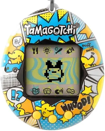
For my final project, I will create a physically interactive Tamagotchi. It is a mini robot creature that the user can pat, touch, spin, and talk to, but instead of being cute and grateful, it responds in unexpectedly pessimistic and slightly hostile ways. The project combines physical interaction through Arduino sensors with a character interface and dialogue system in p5. The concept is inspired by classic Tamagotchi toys, small handheld digital pets that demand constant attention and reward care with affection. In contrast, my project imagines a near-future world in which artificial beings no longer need, or even want, human caretaking. This pet has a personality shaped by human environmental destruction and techno-optimism gone wrong, and it is deeply unimpressed by humans.

Physically, the project will take the form of a small creature-like object mounted on a potentiometer so that the whole robot can be spun like a tiny rotating idol. The main interactions happen through touch and rotation. The user can pat or press the creature via a force sensor embedded in its body, and they can spin it to face different directions using the potentiometer as a rotation input. Inside the body, the creature uses NeoPixels to show changing emotions through light patterns, while on the computer a p5 interface displays a larger animated avatar of the creature and shows its dialogue text.

Unlike typical virtual pets that reward attention with affection and gratitude, this creature is intentionally negative and resistant. When the user pats it, it might snap: “Go away, you silly little human.” When the user spins it so that it faces away, it might respond: “Correct. I prefer not to see you.” If the user keeps spinning it quickly, the creature may complain: “Dizzy. This is abuse, not affection.” When the robot is left facing a corner with its back turned to the user, it may mutter: “Finally. A view without humans in it.” The rotation angle therefore becomes a key part of the interaction design. Different angular positions correspond to different stances or modes of the creature, and those modes drive both the NeoPixel emotion effects on the physical object and the dialogue responses on the p5 screen.

On the Arduino side, the project relies on two main inputs that are sent to p5 over serial communication. The first is a force sensor used as a pat or squeeze input. The Arduino continuously reads the analog value from the FSR, maps the raw reading to a smaller range such as 0 to 10 representing pat intensity, and sends this information to p5 in the form of tagged serial messages like “PAT:<value>”. A reading of “PAT:0” would mean no touch, while something like “PAT:9” would correspond to an aggressive squeeze. The second input is the potentiometer that encodes the robot’s rotation angle. The creature is physically attached to the shaft of the potentiometer so that when the user spins the creature, they are directly rotating the pot. The Arduino reads the analog value from the potentiometer, originally in the range 0 to 1023, and maps it either to a normalized angle between 0 and 359 degrees or to a set of discrete orientation zones. For example, Zone 0 can represent facing the user, Zone 1 slightly turned to the left, Zone 2 slightly turned to the right, and Zone 3 completely turned away with its back to the user. The Arduino then sends periodic messages to p5 such as “ANGLE:<value>” for the continuous angle or “ZONE:<id>” for the discrete orientation. As a stretch feature, the Arduino can also compare the current angle with the previous reading to estimate spin speed and send additional messages such as “SPIN:FAST” or “SPIN:SLOW” if there is enough time to implement this.

The Arduino is also in charge of several outputs, primarily the NeoPixels that visualize the creature’s emotional state. The NeoPixels are used to display different moods and orientations through color and animation patterns. The Arduino listens for commands coming from p5, such as “MOOD:ANGRY”, “MOOD:BORED”, “MOOD:AMUSED” or “MOOD:DISGUSTED”, and possibly additional tags like “DIR:FRONT”, “DIR:LEFT”, “DIR:RIGHT” and “DIR:BACK” that encode the direction it should appear to be facing. For each combination of mood and orientation, the Arduino selects a specific pattern from a small internal lookup table of NeoPixel animations. For instance, when the creature is facing the user and annoyed, the LEDs might show sharp, high-contrast flashing patterns. When it is turned away, the colors might become dim and cold to signal that it is ignoring the user. When the user spins it quickly, it might display chaotic, flickering lights to suggest dizziness and disturbance. In this way, the Arduino acts as the body-level controller that turns high-level mood messages from p5 into concrete light and motion behaviors on the physical pet.

On the p5 side, the program handles visual behavior, dialogue, and integration of the serial data coming from Arduino. The main visual element is a two-dimensional avatar of the creature whose orientation mirrors the potentiometer readings. When Arduino reports that the creature is in Zone 0, facing the user, the avatar will be drawn facing forward. When it reports Zone 1 or Zone 2, the avatar will turn slightly left or right. When it reports Zone 3, the avatar will show its back or a dismissive side profile. Background layers or subtle interface elements can reinforce the sense of orientation, for example by using a spotlight effect when the creature faces the user, and a shadowy or desaturated background when it turns away.

The p5 sketch keeps track of several state variables. It records the current orientation zone or angle reported by Arduino, the most recent pat intensity from the “PAT:<value>” messages, and the time since the last interaction to detect whether the user is ignoring the creature or constantly bothering it. Based on these values, p5 chooses a mood state such as “Annoyed”, “Dizzy”, “Dismissive” or “Begrudgingly Attentive”. That mood state determines the avatar’s expression, including eyes, mouth shape, and posture, as well as background color or small motion effects like shaking or pulsing. Whenever the mood changes, p5 also sends the corresponding mood label back to the Arduino, for example “MOOD:DISMISSIVE”, so the NeoPixels can stay synchronized with the on-screen visuals.

Dialogue and personality are deeply connected to rotation and touch. p5 interprets the angle or orientation zone in semantic terms. When the creature is facing the user in Zone 0, it selects lines that complain about being watched, such as “Why are you staring? I do not perform on command.” When it is turned slightly away in Zones 1 or 2, it may comment on the user’s persistence with lines like “You still there? Unfortunately, yes.” When it is turned completely away in Zone 3, it chooses more extreme dismissive phrases such as “This direction is better. Less human.” If the system detects fast spinning, it can draw from a set of dizzy or abused responses like “Stop spinning me. I am not a fidget toy.”

Beyond instantaneous input, p5 maintains some simple memory over time. It tracks how often and how strongly the creature has been patted in the recent past and how often the user has spun it back and forth between zones. By combining rotation data with touch data, the system can generate interaction-dependent responses. For example, if the user keeps forcing the creature to face them by repeatedly moving it back into Zone 0 after it has “chosen” to be in Zone 3, the creature can complain about humans forcing attention with lines such as “You keep dragging me back. Typical human behavior.” If the user spins it away and then leaves it alone for a while, the system can trigger more subtle, relieved comments like “Finally. A horizon without you.”

The dialogue itself will at minimum be based on prewritten arrays of lines for each mood and orientation combination. p5 will maintain collections such as “linesFacingAnnoyed”, “linesBackTurned” or “linesDizzy” and will choose one line depending on the current mood, orientation zone, and a bit of randomness, to avoid sounding too repetitive. As a stretch goal, the project may integrate an AI API into p5. In that case, p5 would send a short prompt that includes the current mood, orientation description (such as “facing”, “back turned”, “spun fast”), and a brief summary of recent interactions. It would then receive a generated line of dialogue and optionally wrap or filter it to ensure it remains safe, in character, and consistent with the theme. In both the base and stretch versions, the personality remains negative, sarcastic, and skeptical of humans, reflecting a world where artificial beings are not necessarily grateful for their existence or their relationship with their creators.

Week 12: Final Project Proposal

My final project will be a short game/experience inspired by the wish lanterns in Disney’s Tangled and will use the artwork I did all the way back in week 3:

I want users to be able to send out their own wishes. Before they can enter their wish, they must complete a short challenge. The challenge is a physical reaction-time game: four lanterns (each with an LED inside) are paired with four corresponding push buttons. The lanterns light up randomly at a fast pace, and the user must quickly press the button for the lantern that lights up, essentially “whacking” it. Their successful hits are tracked and displayed in p5, with a similar sketch as the one above as the background.
Once the user reaches 10 successful hits, a text box appears in the p5 interface (as already present in the sketch above) where they can type their wish. That wish is then displayed on an Arduino screen, all the lanterns light up together, and the Tangled music plays to complete the experience. After this, the p5 screen gives the user an option to restart the experience all over again.

The Arduino handles all the feedback related to the physical input:
it flashes the LEDs in a random, fast paced manner and detects corresponding button presses by the user. Every time a lit up LED’s button is pressed on time, it sends a signal to p5 to increase the score of the user by 1.

On the p5 side, the sketch handles the game logic, tracks the score, maintains the aesthetics, provides the textbox to enter the wish, and sends the wish back to the Arduino. It also gives instructions at the start of the experience to the user and gives them an option to restart at the end.

To get started, I tried to implement the reaction-time game logic with the score-tracking on a small scale using just my own Arduino, breadboard and 4 LEDs. It mostly works, but the LEDs light up too slowly (ignore the interface also):