With Shota Matsumoto
EXERCISE 01: ARDUINO TO P5 COMMUNICATION
Concept
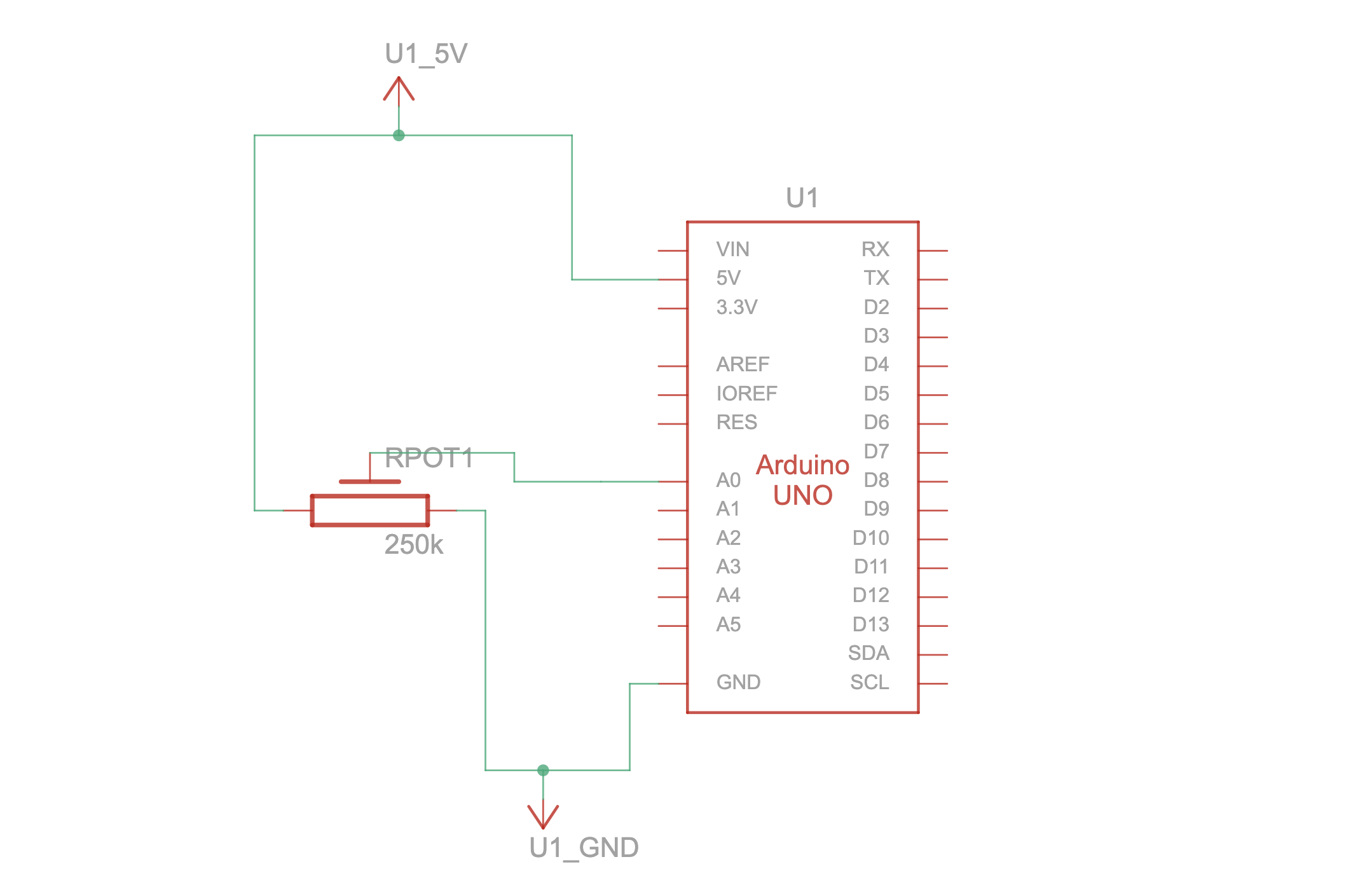
For the first exercise we used a photoresistor as an analog sensor on Arduino to make our ellipse shape move on the horizontal axis in p5. For our code, we adjust it so that with every touch on the photoresistor, the ellipse would move on the canvas.
VIDEO:
https://drive.google.com/file/d/12b1KzwTlo1IQLtDfleAJNJccZhL7J0Tb/view?usp=sharing
Code we’re proud of:
When it comes to the first exercise, the part we are most proud of is the block of code that controls the x-position of the ellipse using the light sensor value from the Arduino. We read the sensor value through the serial port that is connected to the Arduino and map it from 0 to the width of the canvas so that it never goes out of the dimension of the screen.
//read the data coming to the port until the newline character
   let data = port.readUntil("\n");
   //if there is a data
   if (data.length > 0) {
     //convert the clean data into integer
     rValue = int(trim(data));
     //store data of left and right into msg
     let msg = left + "," + right + "\n";
     //send the msg back to the Arduino
     port.write(msg);
   }
   text("rValue = " + rValue, 20, 50);
 }
 //move xpos depending on the sensor value (max = 640)
 let xpos = map(rValue, 550, 900, 0, width);
 fill(0, 0, 255);
 ellipse(xpos, height / 2, 100, 50);
EXERCISE 02: P5 TO ARDUINO COMMUNICATION
Make something that controls the LED brightness from p5.
Concept
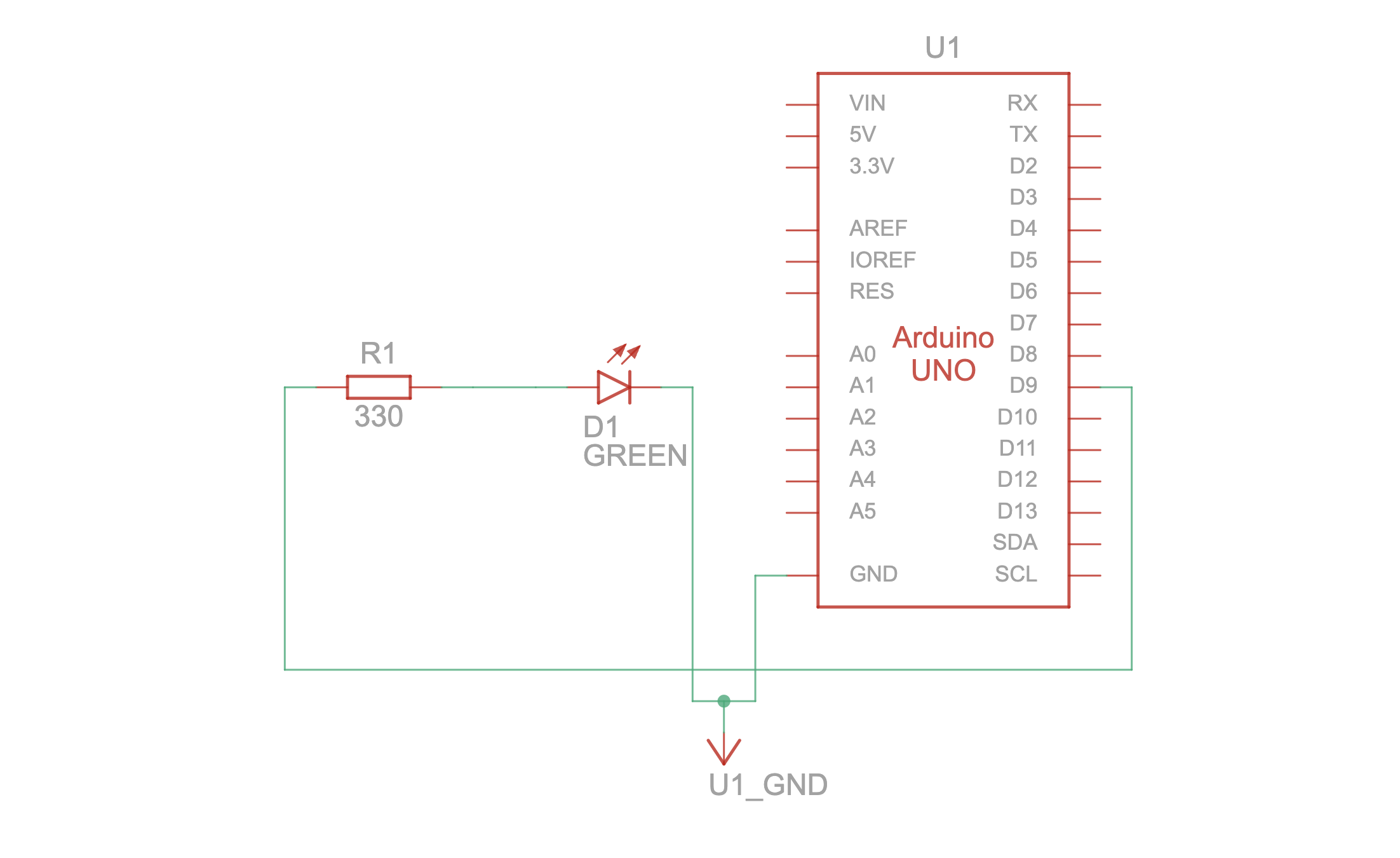
For the second exercise we used the createSlide function to create a slider on the canvas of p5. This way, every time we moved the slider to the right, the brightness of the LED on the Arduino would increase, and every time the slider was moved to the left, the brightness would decrease.
VIDEO:
https://drive.google.com/file/d/12b1KzwTlo1IQLtDfleAJNJccZhL7J0Tb/view?usp=sharing
Code we’re proud of:
For the second exercise, this block of code combines what we learned during the class about p5.js (createSlider) and Arduino. Since we remembered using a slider to control a value or game score, we decided to use it to control the brightness of the LED. We take the slider value, store it in a variable called brightness, and send it to the Arduino through the serial port, as shown in the block of the code below.
//read the slider value
 brightnessValue = brightnessSlider.value();
 //if the port is open
 if (port.opened()) {
   //store the brightness value from the slider
   let msg = brightnessValue + "\n";
   //send it to Arduino
   port.write(msg);
 }
EXERCISE 03: BI-DIRECTIONAL COMMUNICATION
Concept
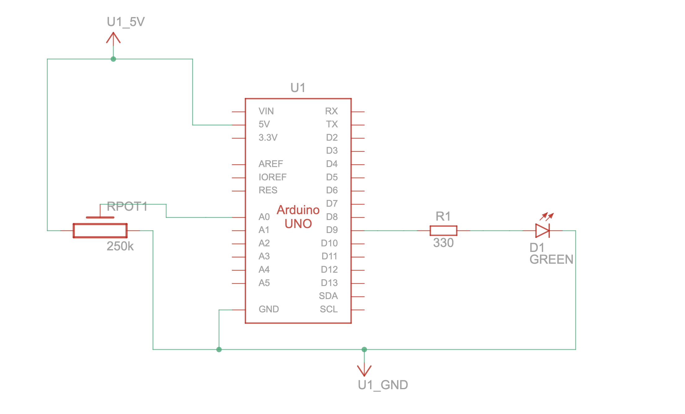
For the third exercise, we made use of a potentiometer ( analog sensor ) on Arduino and a LED light, connecting it on the corresponding pins and then connecting Arduino UNO with P5. After adding the necessary codes on P5, we adjusted our “ball” so that every time it bounced against the floor, the LED would light up, and once it stopped bouncing the LED turned off. With the potentiometer, we were able to control the “wind”, causing the ball to be pushed from side to side, depending on the direction in which we turned the potentiometer.
VIDEO:
https://drive.google.com/file/d/1YA0d_xkwM2zxTco6mqnZNbEIr9Ou60oq/view?usp=sharing
Code we’re proud of:
For the third exercise, we’re proud of the block of code below. It basically captures the main objective of this exercise. When the ball reaches the ground and the LED state is 0, meaning the LED is currently off, we turn it on by sending a 1 to the Arduino through the serial port. It is simple but we needed to understand the basics of what is going on in the vectors.
//if the ball reached the floor and the led is currently off
 if (isBounced && ledStatus === 0) {
   //turn the LED on
   port.write("1");
   //set the state to 1
   ledStatus = 1;
 }
 else if (!isBounced && ledStatus === 1) {
   //turn the led off
   port.write("0");
   ledState = 0;
 }
Github
Links:
Challenges and Further Improvements
Fortunately, we were able to complete all the assignments successfully, and managed to achieve all the necessary responses of P5 and Arduino. For each exercise, we started by planning out which tools we would use, how to arrange them on our breadboard, and once this was done, our greatest challenges consisted of arranging and adding the codes required to make each response function. On the third assignment we especially struggled writing the codes required to make the potentiometer affect the “wind” and consequently the direction in which the ball was pushed. For future improvements, we would like to grasp a better understanding of the exchanges between P5 and Arduino in order to make more complex and interactive responses that can also satisfy the assignment’s requirements.
References:
We used ChatGPT to help us understand the bouncing ball template code since we hadn’t yet learned about the vector library in class. After understanding the foundation of it, we were able to integrate the isBounced logic into the template code to detect whether the ball was bouncing or not. Thus, we’re glad we were able to learn a lot about vectors library. We also used ChatGPT to learn about DOM library methods such as .position() and .style(). Although we had covered the basics of createSlider, we didn’t delve deeper into it during the class, so we needed to learn how to adjust its position and CSS styling of the ball.