Final Project Documentation

Concept

The concept is recreation of the experience of walking through a gallery, through two mediums. In this work the floor plan board and the p5 virtual gallery are in conversation with each other. Where there are parallels in each artwork, where each two of the four works interact with each other and explore similar themes but in different mediums. They explore audio and visuals, where each medium has a different take on each. I wanted to also have a reflection of my journey in this class, which is why a lot of the works are inspired by previous assignments, reflecting my journey.

Video

IMG_9067

Description of interaction design

This project merges a physical Arduino-based floor-plan board of the gallery with a virtual 3D gallery built in p5.js. When the user presses one of four force sensors, they “walk” toward a corresponding artwork in the digital gallery, and a central toggle switch lets them enter or exit the artwork’s full-screen view. The Arduino constantly sends live sensor data to p5.js, while p5.js sends feedback, lighting LEDs and playing buzzer sounds, back to the board to make the physical and virtual experiences feel seamlessly connected.

Schematic of your circuit

Description of p5.js code

The p5.js code sets up the simulation using WEBGL to create a 3D experience where the user can navigate the 3D space. It begins with an introduction screen where you connect the arduino before you enter the gallery and receive a few instructions. When the user is close to an artwork, the artwork will be highlighted yellow, then they can enlarge it using the toggle button on the floor board, where they will experience 4 different artwork experiences based on which frame they select. Two of the artworks explore visuals, while the other two explore audio. The main audio works, plays two different songs depending on whether or not the user is playing, while the visual changes the color of the work depending on the location of the cursor of the user.

Description of Arduino code 

The arduino code controls the four force sensors, dividing their input into 4 categories each of which corresponding to a specific speed. It sends over to the p5 the values of the sensors along with the state of the toggle button. It also has 4 LEDs that it controls depending on the signal from the p5.js, to signal which artwork is currently being explored by the user and a buzzer to signal the opening and closing of a work. Further in parallel with the works in p5, one of the works plays a melody on the buzzer while the other controls the flashing on an LED.

Description of communication between Arduino and p5.js

There is multiple levels to the communication between arduino and p5.js, where arduino sends out signals in levels for the speed for each of the force sensors. It signals which force sensor is being pressed and how hard it is being pressed. It also has a toggle switch that controls when the artworks are opened and closed when the user is close to an artwork. There is also a buzzer that plays a note every time a work is opened or closed. Then there are the 4 leds that get signals from p5 on when to turn on, when the works are selected as well.

Arduino Code

Github Link

P5 Sketch

What are some aspects of the project that you’re particularly proud of?

The exploration of a 3D space created a more interactive experience for the user, and I am proud of the work I put into creating a smooth movement with the sensors. I wanted to create a space that reflected the feeling of being in a gallery well, and I believe that included a smooth and seamless experience, which is why a lot of my time went into maintaining a minimalist but functional interface. Further, I believe the placement of the sensors and the toggle switch were quiet efficient for the user navigation and reflective of the virtual space well.

Future Improvements

I’d like to create a more intricate gallery with more works, maybe expanding it to different rooms. With potential of creating it for spaces on campus, giving a virtual representations of works, or even just the sensor navigation for regular spaces. I believe I like the idea of the interaction of the virtual and the physical and would like to explore the potential of using other sensors or physical elements to have a more engaging and interactive experience that explores more themes and expands the bounds of what this project covers.

Showcase User Trials

IMG_9070

IMG_9074

IMG_9075

IMG_9087

KICK ‘N’ SAVE – Final Project

Concept

For my final project in Intro to IM, I created KICK ‘N’ SAVE, an interactive penalty-kick game that combines Arduino hardware, a joystick + arcade button, p5.js animation, and machine-learning hand-tracking using ML5’s Handpose model.

The idea was to create a soccer experience where the player controls the shooter with a physical joystick, while the goalkeeper is controlled by hand gestures picked up by a webcam. This combination of digital and physical interaction makes the gameplay energetic, intuitive, and fun for spectators.

The goal was to build something that feels like an arcade mini-game, is simple to understand immediately, and still feels alive because of the hand-controlled goalkeeper.

Images of the Project

Schematic

User Testing Videos

Video 1

How the Implementation Works

Interaction Design:

KICK ‘N’ SAVE involves two simultaneous interactions:

  • Shooter (player 1):
    Uses a physical joystick

    • Tilt ← → to select shot direction

    • Press the push button to shoot

    • LED flashes green if a goal is scored

  • Goalkeeper (player 2):
    Controlled by hand gestures using a webcam

    • Move hand to left/center/right

    • ML5 Handpose tracks the index fingertip

    • Keeper smoothly lerps toward the detected zone

    • Attempts to block the shot

The design intentionally creates a duel between physical and digital control.

Arduino Code:

The Arduino handles:

  • Joystick left/middle/right detection

  • Button press detection for shooting

  • LED flashing animation when p5.js sends ‘G.’

  • Serial communication to send ‘L’, ‘M’, ‘R’, and ‘S’ to p5.js

Code Snippet

// PIN DEFINITIONS

const int xPin = A0;        // Joystick XOUT
const int buttonPin = 2;    // Joystick Button (SEL)

const int GREEN_LED_PIN = 10; // Green LED (NOW: Arcade Button Light)

// JOYSTICK THRESHOLDS

const int thresholdLow = 400;
const int thresholdHigh = 600;

// State variables
String lastDirection = "M";  // Start in middle
int lastButtonState = HIGH;

// LED flash duration (1 second flash)
const int LED_FLASH_TIME = 1000;

void setup() {
  Serial.begin(9600);

  pinMode(buttonPin, INPUT_PULLUP);

  pinMode(GREEN_LED_PIN, OUTPUT);

  digitalWrite(GREEN_LED_PIN, LOW);
}

void loop() {

  // A. HANDLE LED COMMANDS FROM p5.js
  if (Serial.available() > 0) {
    char c = Serial.read();

    if (c == 'G') {
      digitalWrite(GREEN_LED_PIN, HIGH);
      delay(LED_FLASH_TIME);
      digitalWrite(GREEN_LED_PIN, LOW);
    }
    else if (c == 'R') {
      // Do nothing
    }
  }

  // B. READ JOYSTICK X-AXIS

  int xVal = analogRead(xPin);
  String currentDirection;

  if (xVal < thresholdLow) currentDirection = "L";
  else if (xVal > thresholdHigh) currentDirection = "R";
  else currentDirection = "M";

  if (currentDirection != lastDirection) {
    Serial.println(currentDirection);
    lastDirection = currentDirection;
  }

  // C. READ JOYSTICK BUTTON (SHOT)
  int buttonState = digitalRead(buttonPin);

  if (buttonState == LOW && lastButtonState == HIGH) {
    Serial.println("S");
  }

  lastButtonState = buttonState;

  delay(50);
}

Here is the link to the full code on GitHub: Github

p5.js Code:

The p5.js sketch handles:

  • Rendering the game visuals

  • Animating the ball based on the joystick-chosen direction

  • Keeper movement driven by ML5

  • Collision detection

  • Sending ‘G’ or ‘R’ back to Arduino

Embedded sketch

Parts of the Project That I’m Proud of

One of the things I’m most proud of in this project is how naturally the hybrid interaction system came together. The combination of a physical joystick for the shooter and ML5 hand tracking for the goalkeeper created a dynamic, two-sided experience that feels genuinely interactive and different from typical p5.js games. I’m also especially proud of the smooth goalkeeper movement—using lerp() to reduce jitter made the keeper feel responsive yet realistic, which dramatically improved gameplay. I’m also pleased with the UI design, especially the cartoon-style intro page, which gives the game a professional and cohesive look. On the technical side, achieving stable serial communication between Arduino and p5.js—with no dropped signals—was a big accomplishment and made the hardware and software feel seamlessly connected. Altogether, these elements make the project feel less like a school assignment and more like an actual mini-game someone might find in an arcade or mobile app.

Link to Resources Used

AI Tools Referenced

I used AI tools in the following ways:

ChatGPT

  • Helped debug Arduino serial issues

  • Helped rewrite and clean p5.js classes

  • Guided merging of joystick logic with animation logic

  • Assisted in writing ML5 code for controlling the goalkeeper in the three directions

Gemini

  • Helped generate images used for the project (intro page image, goalkeeper image, shooter image)

Challenges Faced & How I Overcame Them

1. ML5 Handpose jitter
  • Solved using lerp() for smoother movement

  • Added 3-zone classification instead of direct x-values

2. Joystick sending multiple repeated values
  • Fixed by only sending direction when it changes

3. Arduino errors from invisible characters
  • Caused by stray UTF-8 spaces

  • Solved by rewriting the affected lines manually

4. Serial communication timing issues
  • Added delays + ensured consistent baud rate

  • Verified using the p5 serial monitor

5. Resizing issues
  • Used scaleFactor everywhere based on the window height

  • Updated positions inside windowResized

Areas for Improvement

Looking ahead, there are several exciting improvements I’d love to bring into future versions of this project. One of the biggest upgrades would be enhancing the core game mechanics – especially by adding variable shot power so the ball’s speed and curve depend on how long the shooter holds the button. This small change would instantly add depth and skill to the gameplay. I also want to rethink how the goalkeeper reacts by introducing a realistic “dive” mechanic that forces quick decisions instead of constant tracking, making the challenge more balanced and intense. On the user experience side, adding a subtle aiming line for the shooter and a clear tracking-zone guide for the goalkeeper would solve most of the confusion players currently face. Technologically, expanding the serial communication to include haptic feedback or LED signals would make the hardware feel more alive and connected to the game. And finally, introducing polished animations – like a proper kick sequence or a dramatic save – as well as a slight 3D-style pitch perspective would elevate the visual experience far beyond the current prototype. All together, these improvements could transform the game from a fun demo into a fully immersive, replayable mini-sports experience.

IM Show Documentation

Video 1

Tokyo Flight (Final Project by Shota)

Main Concept:

As a super ambitious Ghibli fan, it has always been my dream to step into a Ghibli world, especially The Wind Rises, the film about an aviation engineer during World War II. For this final project, I made my dream come true by creating an interactive game called Tokyo Flight where users can experience flying in the sky and controlling their own plane as a pilot. The game is controlled using a handmade physical airplane that I designed and built with a 3D printer. It includes an accelerometer to measure the plane’s tilt angle, a button to boost its speed, and LED lights that illuminate the airplane during gameplay. The objective is simple: collect as many stars as possible without getting hit by bombs.

Interaction Design:

Tokyo Flight is very interactive due to the effective communication between Arduino and p5. First of all, users control the airplane on the screen using a unique handmade airplane controller. During user testing, people found it very unique and interesting because it made them feel like they were actually flying in the sky, and they had never used this kind of controller before, so I am very proud of it. Furthermore, there is a button on the airplane that users can press to boost the plane’s speed on the screen. There are also LED lights on top of the controller so that users can see when they collect stars, reflecting the actual lights on real airplanes. Overall, the smooth communication between Arduino and p5, along with the unique controller, makes the game very interactive.

P5 Code:

Since my final project is an interactive game, my code uses different game states, and depending on which state the user is in, it displays the corresponding screen and either shows buttons or allows them to play the game. This is exactly what we learned in class before the midterm about using game states to control the flow of the game, so I applied that technique here. I also used the sprite trimming technique we learned in class. This time, however, I struggled to cut out each plane cleanly since the distances were not measured accurately. I tried adding padding, but the current state is the best I could do to make each plane size look consistent. 

// get the width and height of the spritesheet
  let imageWidth = spritesheet.width;
  let imageHeight = spritesheet.height;
  
  // get the number of images in row and col
  let cols = 5;
  let rows = 6;
  let cellWidth = imageWidth / cols;
  let cellHeight = imageHeight / rows;
  
  // some padding between the images
  let padding = 5;
  
  airplaneSkins = [];
  
  // use the template from the class slides 
  // extract each plane from the spritesheet
  for (let row = 0; row < rows; row++) {
    for (let col = 0; col < cols; col++) {
      // get the position and the size of each image 
      let x = col * cellWidth + padding;
      let y = row * cellHeight + padding;
      let w = cellWidth - (padding * 2);
      let h = cellHeight - (padding * 2);
      
      // ensure we don't go outside the image bounds
      x = max(0, min(x, imageWidth - w));
      y = max(0, min(y, imageHeight - h));
      w = min(w, imageWidth - x);
      h = min(h, imageHeight - y);
      
      // extract the image if it is not empty
      if (w > 0 && h > 0) {
        let img = spritesheet.get(x, y, w, h);
        airplaneSkins.push(img);
      }
    }
  }


The part of the code that I am particularly proud of is mapping the sensor value from the accelerometer to the vertical position of the airplane. Since the sensor value ranged from 285 to 380, I set those as the minimum and maximum values and mapped them to the plane’s y position. I also added a threshold to prevent the plane from jittering. I initially tried controlling it through delay on the Arduino, but because I wanted the movement to feel more stable and robust, I implemented the threshold instead.

// function to control the airplane's movement 
function updateControls() {
  let moveUp = false;
  let moveDown = false;
  // detect whether the space bar or the button is pressed or not
  let boosting = keyIsDown(32) || buttonPressed;
  
  // if the sensor is connected and the port is open
  if (useSensor && port && port.opened()) {
    // map the sensor value from the accelerometer to the plane's y position 
    let targetY = map(sensorValue, 285, 380, plane.size / 2, height - plane.size / 2);
    // store the current y position of the plane
    let currentY = plane.y;
    // get the difference 
    let diff = targetY - currentY;
    
    // the plane only moves if the difference is larger than the threshold 
    let threshold = 3;
    if (abs(diff) > threshold) {
      if (diff > 0) {
        moveDown = true;
      } else {
        moveUp = true;
      }
    }
  } else {
    // if the sensor is not connected, then use keyboards to control
    moveUp = keyIsDown(UP_ARROW);
    moveDown = keyIsDown(DOWN_ARROW);
  }
  
  return { moveUp, moveDown, boosting };
}


Full P5 Code

Arduino Code

My Arduino code is fairly simple since I used some of the class templates. For the accelerometer, because we need to map the sensor value to the plane’s y position in p5, we use analogRead(A0) to read the sensor value from analog pin A0 and send it to p5 through the serial port. Likewise, we read the sensor value from the button using digitalRead(). For the LED lights, we read one character from p5: if it is 1, we turn on both LED pins; if it is 0, meaning the user is not collecting stars, we turn them off. I also set a delay of 100 to prevent sending sensor values to p5 too rapidly, which would make the plane shake due to the accelerometer’s sensitivity.

// pin to read button press 
const int buttonPin = 2;

// LED pints to light up when stars are collected
const int led1 = 8;
const int led2 = 9;

unsigned long ledOnTime = 0;  // record when the LED turns on 
const unsigned long ledDuration = 500;  // LEDs turn on after 500ms

void setup() {
  Serial.begin(9600);
  pinMode(buttonPin, INPUT); // set to input since we want to send sensor values 
  pinMode(led1, OUTPUT); 
  pinMode(led2, OUTPUT);
  digitalWrite(led1, LOW); // turn off first
  digitalWrite(led2, LOW);
}

void loop() {
  int x = analogRead(A0); // read accelerometer value (0 to 1023)
  int btn = digitalRead(buttonPin); // read the button state 
  Serial.print("ACC:"); 
  Serial.print(x); // print accelerometer value
  Serial.print(",BTN:");
  Serial.println(btn); // print the button state (1 if is's pressed)

  if (Serial.available()) {
    char c = Serial.read(); // gets one character from p5
    if (c == '1') { // if it is 1
      // turn on the LED pins
      digitalWrite(led1, HIGH);
      digitalWrite(led2, HIGH);
      // save the time so that LEDs can turn off automatically after 500 ms
      ledOnTime = millis();
    }
    if (c == '0') { // if it is 0
      // turn off the LEDs 
      digitalWrite(led1, LOW);
      digitalWrite(led2, LOW);
      // reset the timer to 0
      ledOnTime = 0;
    }
  }

  // if the LED has been lighting up for more than 500 ms
  if (ledOnTime > 0 && (millis() - ledOnTime) >= ledDuration) {
    // turn both off
    digitalWrite(led1, LOW);
    digitalWrite(led2, LOW);
    ledOnTime = 0;
  }

  // set delay to 100 so that plane on p5 won't be too sensitive 
  delay(100);
}

Full Arduino Code

Communication between P5 and Arduino:

Arduino and p5 communicate with each other in three ways. First, the accelerometer on the plane controller measures the tilting angle and sends sensor values to p5 so that the plane on the screen moves up and down accordingly. Second, there is a button on the plane that boosts the plane’s speed in p5 when pressed. When the button is pressed, we send its sensor value through the serial port, and p5 processes it. Lastly, there are two LED lights on the physical plane. Whenever the plane in p5 collects a star, p5 sends either a 1 or 0 to Arduino to turn the LEDs on or off. This represents communication from p5 to Arduino.

Schematic:

For some reason, the image is too blurry, so you can see the clear image of schematic through the link below:

Schematic (clear version)

User Testing & Experience:

Some people told me that the screen was a bit too laggy, so it was a little hard to play. Since this is a technical issue related to my laptop, I think I will need to use a better computer with a stronger CPU. I also received feedback at the IM show, and one professor mentioned that it would have been very nice if the airplane were shown from the user’s perspective. That way, the game would feel more interactive and immersive. So next time, I will improve the UI and make users feel like they are actual pilots.

These are the videos of users I filmed during IM Show.

User 1

User 2

User 3

What are some aspects that you are particularly proud of: 

I’m especially proud of the button on the physical airplane because it was very challenging to embed it securely. At first, I considered using a LEGO block to hold the button in place, but it was too unstable. Instead, I decided to make a hole in the plane and embed the button directly. To do this, I asked a professor from Creative Robotics to help me understand how to use different drills to create a precise, tiny hole for the button. I also used a glue gun to attach it firmly to the plane. As a result, the button became very stable.

Future Improvements:

For future improvements, I would like to add a vibration motor to the physical airplane so that users can feel feedback when the plane in p5, for example, gets bombed. Additionally, since there are currently many wires coming out of the airplane, I want to reduce them to make the controller easier to use. In terms of UI, I want to add a moving character on the plane so that users feel as if they are actually riding it. I believe these improvements would make the game more interactive and visually engaging.

References:

For resources, I watched this tutorial ( https://www.youtube.com/watch?v=zpV7ac3ecl4 ) to learn how to use the accelerometer, especially because I didn’t know how it worked. It helped me understand which pins to connect and that there are 3 vectors I can use to measure the tilting angle. I also used ChatGPT to adjust the position and size of each button and screen element using getScale and scaleSize, which are custom functions I designed. The getScale() function helped me pick the smaller ratio between (800, 600) and (curWidth, curHeight), and use it as a base scale factor, which we multiply by the size of each element inside scaleSize(). This effectively helped me adjust the position and size of each component both in fullscreen and non fullscreen modes.

Furthermore, I learned about localStorage, which is a browser API that allows user data to persist on their browser even after they close it. This helped me create a persistent leaderboard that can store as much user data as needed. Lastly, I asked ChatGPT to figure out why the LED lights were not lighting up properly, and it told me that I had not placed the wire in the correct position. I used the class templates, but ChatGPT helped me work through the additional details I needed to complete my interactive game.

Final Project

Concept

During my visit to the US this November, I had the chance to see an original Claude Monet painting at Princeton University, and that experience I believe became the spark for this entire project. Standing in front of the canvas, I was struck not just by the colors, but by how alive the surface felt, how the brush strokes seemed dissolve depending on where I focused my eyes. There was a sense of motion and atmosphere that I had never fully appreciated in prints or online images.

After the initial direction of my project didn’t go as intended, I knew immediately that I wanted to recreate that feeling, trying to capture the energy of his mark-making using code, video, and interactive hardware. In a way, this project became my attempt to translate the emotional impact of that painting into a dynamic, generative medium of my own.

So, yes, my idea is simply a filter that turns the live footage from camera to a relatively similar style.

Photos / Video of Project Interaction

IMG_2924

How the implementation works

The implementation consists of three interconnected layers:

1. Hardware (Arduino Uno)

The Arduino reads five physical inputs:

    1. Potentiometer – controls global scaling of brush strokes
    2. Button 1 – switches to “Venice Sunset” palette
    3. Button 2 – switches to “Water Lilies” palette
    4. Button 3 – switches to “Sunrise + Viridian” palette
    5. Button 4 – triggers a photo snapshot

The Arduino packages these values into a comma-separated serial string and sends them to the browser.

2. p5.js

The browser receives the serial data via the Web Serial API.
p5.js:

    1. Analyzes the webcam image pixel-by-pixel
    2. Computes local edge gradients using a Sobel operator
    3. Generates a flow field for stroke direction
    4. Combines brightness, edge magnitude, radial position, and noise to determine stroke color, size, and jitter
    5. Paints small stroking particles each frame and adjust color modes, scale, and triggers photo capture


3. Interaction Design

Physical Inputs → Arduino → Serial → p5.js → Painter Engine → Screen Output

Arduino Code
const int POT_PIN = A0;
const int BTN1_PIN = 2;
const int BTN2_PIN = 3;
const int BTN3_PIN = 4;
const int BTN4_PIN = 5;  

void setup() {
  Serial.begin(9600);
  pinMode(BTN1_PIN, INPUT_PULLUP);
  pinMode(BTN2_PIN, INPUT_PULLUP);
  pinMode(BTN3_PIN, INPUT_PULLUP);
  pinMode(BTN4_PIN, INPUT_PULLUP);  
}

void loop() {
  int potValue = analogRead(POT_PIN);
  int btn1 = !digitalRead(BTN1_PIN);
  int btn2 = !digitalRead(BTN2_PIN);
  int btn3 = !digitalRead(BTN3_PIN);
  int btn4 = !digitalRead(BTN4_PIN); 
  
  Serial.print(potValue);
  Serial.print(",");
  Serial.print(btn1);
  Serial.print(",");
  Serial.print(btn2);
  Serial.print(",");
  Serial.print(btn3);
  Serial.print(",");
  Serial.println(btn4);  
  
  delay(50);
}

Description of p5.js code and embed p5.js sketch in post

The p5.js sketch is responsible for everything visual. It uses several coordinated systems:

A. Webcam + Pixel Processing

Each frame is analyzed for, brightness, edges (using Sobel filter), and radial distance from center. This information determines where strokes should appear.

B. Flow Field

Edge gradients produce an angle for each region of the image. Brush strokes follow this angle, creating the illusion of form and direction.

C. Monet-Inspired Color Logic

I handcrafted three color transformation modes that reinterpret facial features differently depending on shadow, mid-tones, and highlights.

D. Stroke Drawing

Hundreds of tiny “tracers” travel across the video frame, leaving curved paths like brush strokes. Noise adds natural variation.

E. Arduino Controls

    1. Potentiometer adjusts scale
    2. Buttons switch color modes
    3. Button 4 triggers takePhoto()

Communication Between Arduino and p5.js

Communication relies on the Web Serial API, which allows a webpage to read from an Arduino.

What I’m proud of the most

What I’m most proud of is the generative painting engine. I wasn’t sure at first if I could combine live video input with a brush-stroke system that feels expressive instead of random, but the structure I ended up building feels genuinely satisfying. The way I compute brightness and gradient values from the webcam frame using a Sobel operator was a challenge, but finally writing:

let gx = (tr + 2 * cr + br) - (tl + 2 * cl + bl);
let gy = (bl + 2 * bm + br) - (tl + 2 * tm + tr);

and seeing the flow field come to life was one of the most rewarding moments of the whole project. That logic is what allows the brush strokes to “hug” the edges of a face, giving the portrait dimension and structure rather than just noise.

I’m also proud of the way the color transformation system turned out. I built three Monet-inspired palettes, but what makes them feel special is the conditional logic that adjusts them based on brightness, edge detail, and whether the region seems to belong to the “face” or the background. In the code, that meant writing a lot of nuanced rules, like:

if (bright < 120) {
  r = r * 0.8 - 10;
  g = g * 0.85 - 5;
  b = b * 1.35 + 40;
}

How this was made

Generative AI (ChatGPT) played a supportive but important role throughout the making of this project. I used it to debug unexpected behavior in my Arduino and JavaScript code, and understand algorithms like Sobel filters and flow fields in more depth. AI also helped me brainstorm interaction ideas and refine parts of the painting logic when I was unsure how to structure them. For the written documentation, AI assisted me in organizing my thoughts, expanding sections, and polishing the final narrative so that it would read clearly and cohesively.


Spidey Sense- Final Project Blog Post

Concept:

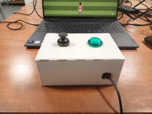
I wanted to make a game that’s fun, fast, and actually feels like you’re Spidey. The core idea is simple: you’re constantly moving forward, jumping from platform to platform, and your goal is to keep going without falling. But the twist is that instead of just pressing a key, I used a glove sensor to make the jumps happen. So when you move your hand, Spidey jumps, it’s kind of like you’re really doing it yourself.

The platforms aren’t all the same, so every run is a little different. Some are closer together, some are higher or lower, and the timing is everything. I wanted the game to feel smooth but challenging, where even a tiny mistake can make you mess up a jump and start over.

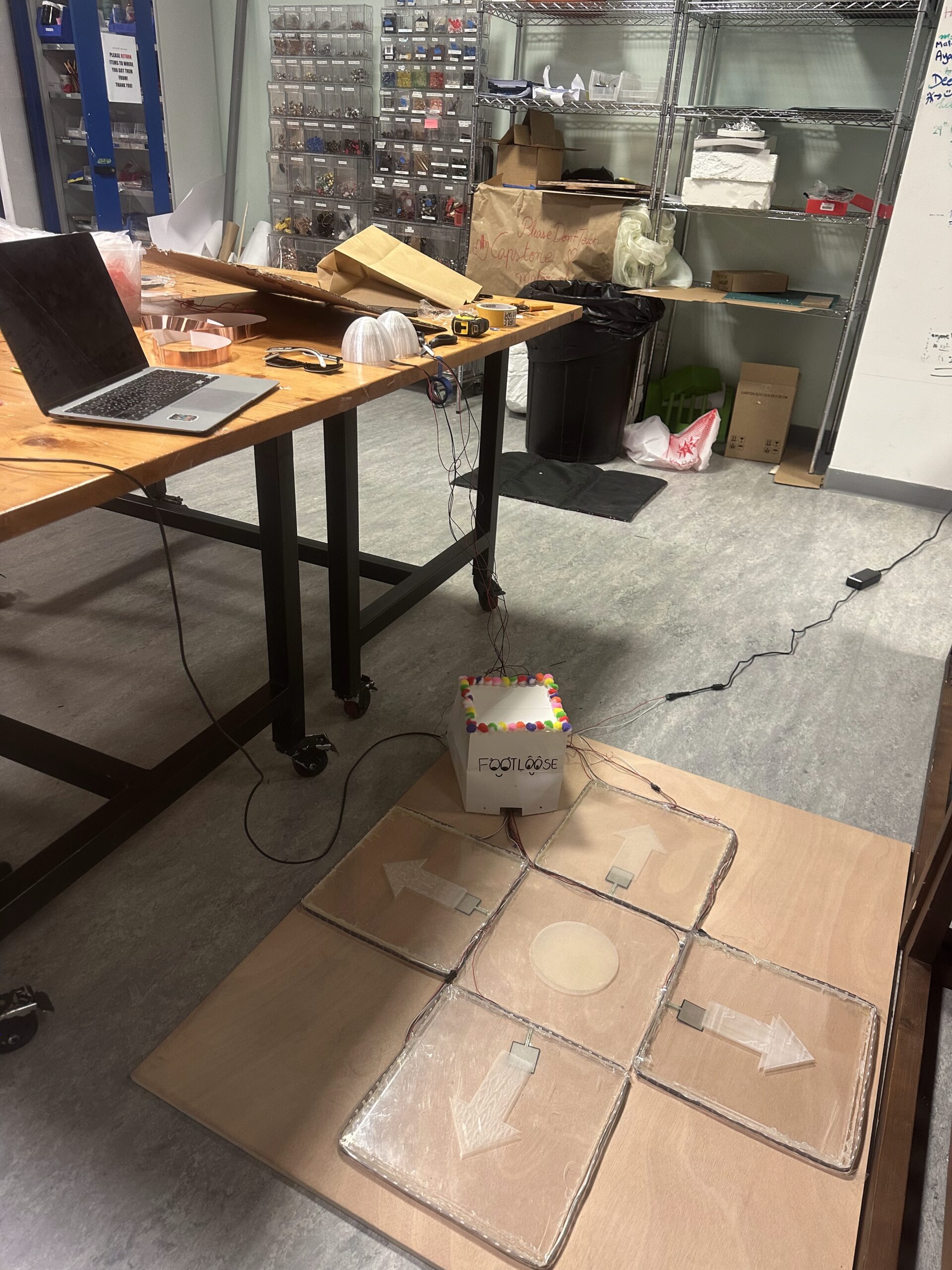
Photos and User Testing Link:

https://drive.google.com/drive/folders/1Ur0xwvngiJKxs0-OA5ZY9DNj2kDOEgcR?usp=sharing
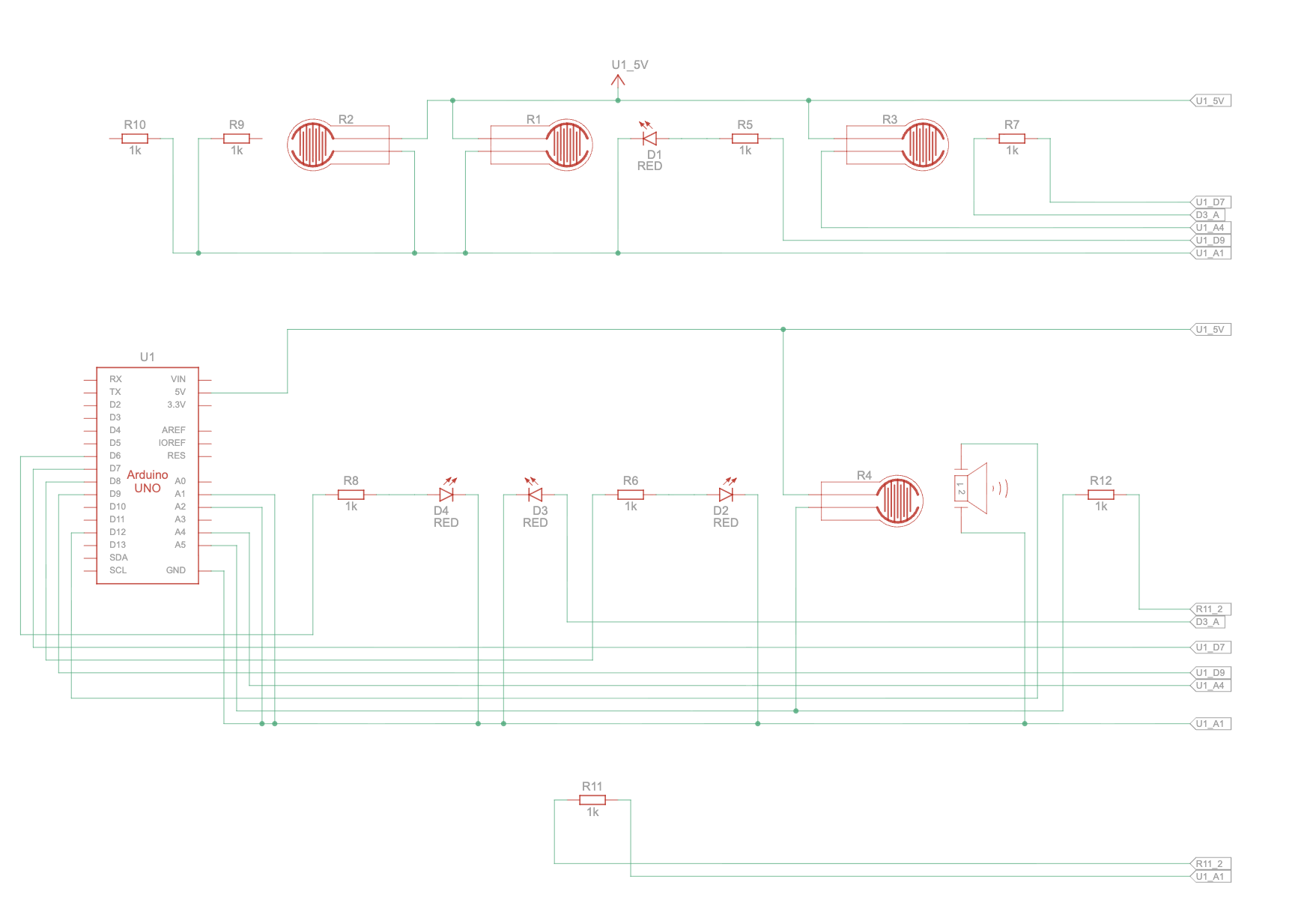
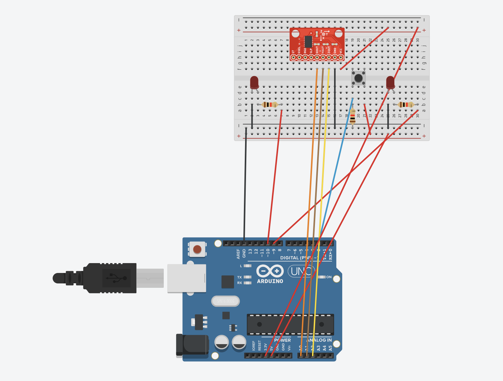
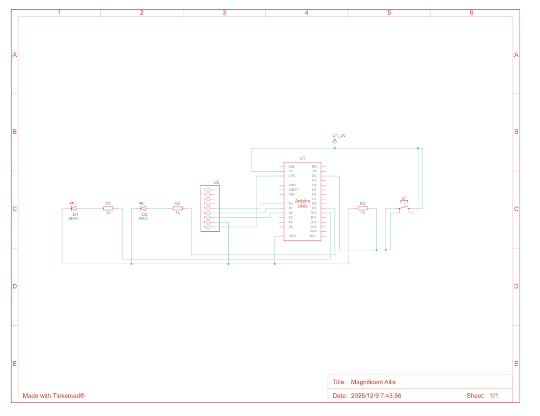
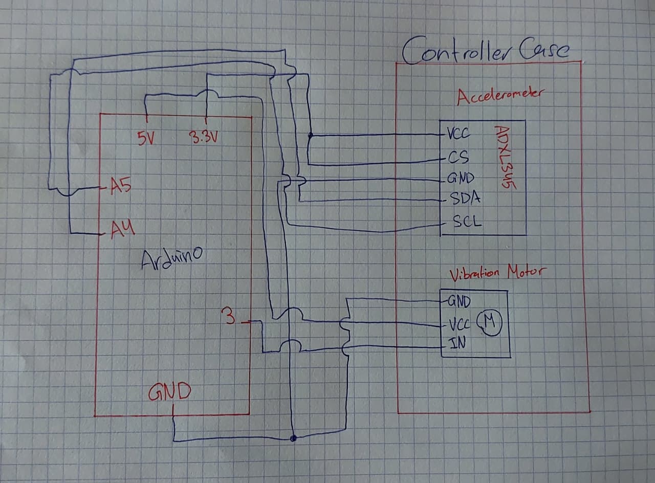
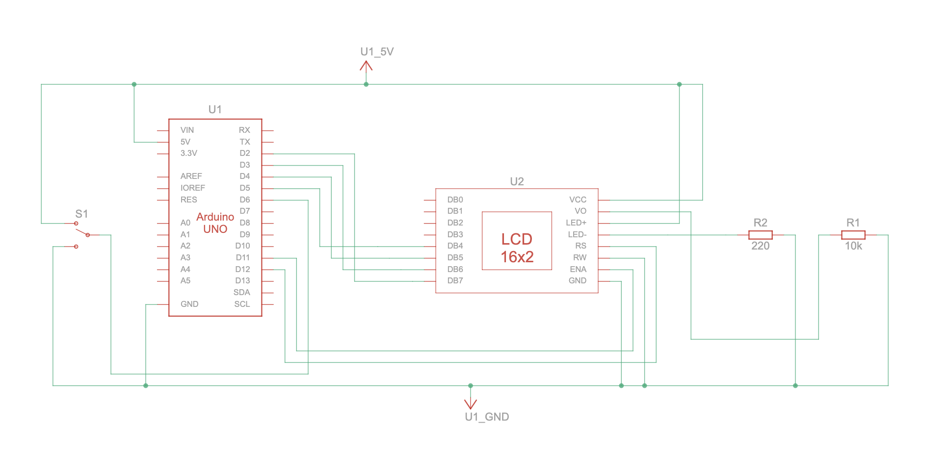
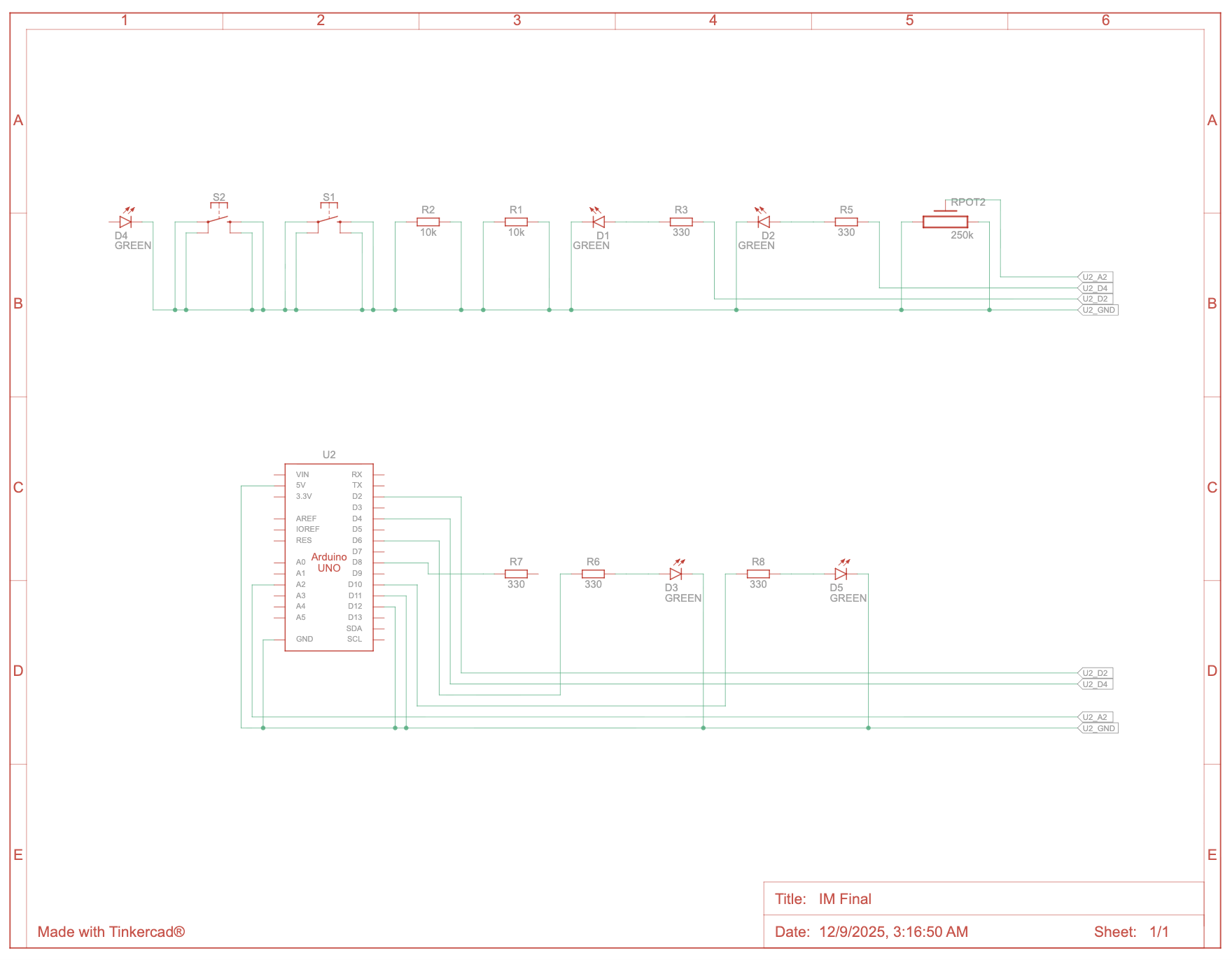
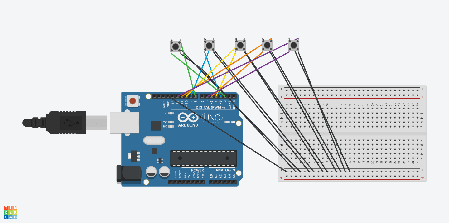
Schematic:

Note: the button is in place of the copper pads, but the same logic in the sense that when the pads touch, it reads 1. 

Implementation:

1. Description of Interaction Design
The interaction design is centered around turning your hand movements into Spidey’s actions on screen:

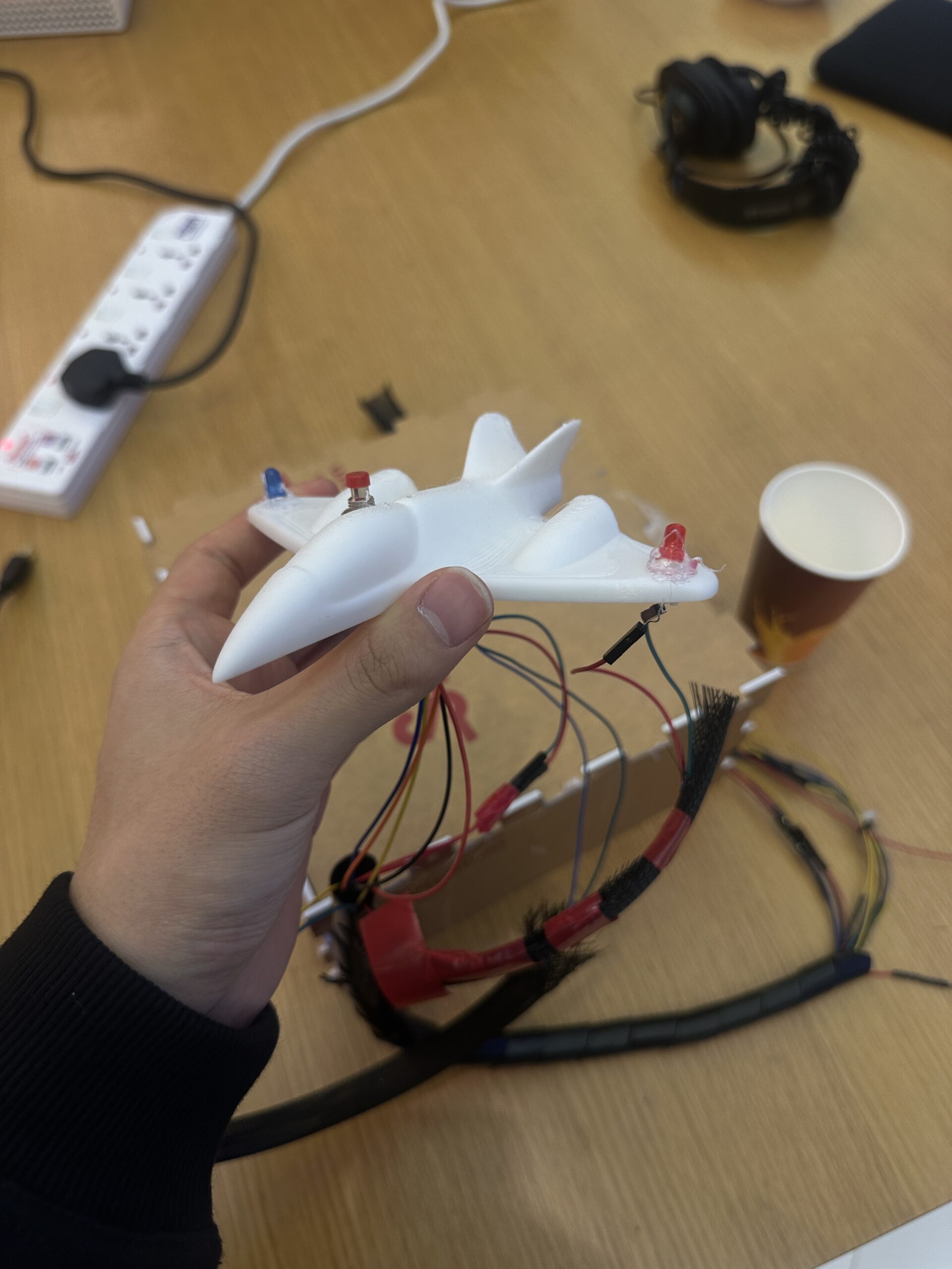
  • When the copper tapes on the glove touch, it triggers Spidey to jump in the game.
  • The glove also has an LED that lights up whenever Spidey jumps, giving physical feedback.
  • The design is intuitive and playful, the player doesn’t need to press buttons; their gesture does the work.

2. Arduino Code
The Arduino reads the glove input and communicates with p5.js over the serial port. It also listens for commands from p5.js to control the LED.


//input from copper tapes
const int glovePin = 7; 
const int ledPin = 8;  

void setup() {
  pinMode(glovePin, INPUT_PULLUP);
  pinMode(ledPin, OUTPUT);
  Serial.begin(9600);
}

void loop() {
  //should read 1 if tapes are touching
  //causing spidey to jump in p5
  //0 if not
  int glove = digitalRead(glovePin) == LOW ? 1 : 0;
  Serial.println(glove);

  //p5 to arduino
  //when spidey jumps, led turns on
  if (Serial.available()) {
    char cmd = Serial.read();
    if (cmd == '1') digitalWrite(ledPin, HIGH); 
    if (cmd == '0') digitalWrite(ledPin, LOW);  
  }

  delay(20);
}

How it works:

Arduino constantly checks if the glove tapes are touching (1) or not (0).

It sends this value to p5.js in real time.

Arduino also listens for ‘1’ or ‘0’ from p5.js to turn the LED on or off, providing visual feedback.

GitHub: https://github.com/kzeina/Intro-To-IM


3. p5.js Code

p5.js handles game logic, graphics, and Arduino communication.

Main flow:

1- Screen flow: Intro → Instructions → Game. Mouse clicks navigate screens.

2- Arduino connection: The game connects to Arduino via the Web Serial API.

3- Glove input: Reads sensorValue from Arduino and triggers Spidey’s jump.

4- LED feedback: Sends ‘1’ to Arduino when Spidey jumps, then ‘0’ after a short delay.

5- Game physics: Applies gravity, jump forces, and platform collisions.

Code snippets:

Reading glove input and controlling LED:

if(sensorValue === 1 && jumpReady && game.started && !game.gameOver) {
  game.jump()
  spidey.playAction("jump")
  jumpReady = false
  setTimeout(() => jumpReady = true, 200)

  if(arduinoConnected) {
    const writer = port.writable.getWriter()
    writer.write(new TextEncoder().encode("1"))
    writer.releaseLock()
    setTimeout(() => {
      const writer2 = port.writable.getWriter()
      writer2.write(new TextEncoder().encode("0"))
      writer2.releaseLock()
    }, 150)
  }
}

Platform generation, scrolling, and collision handling:

//update game physics and platform scroll each frame
update() {
  if(this.gameOver) return;

  //handle intro/start delay before game begins
  if(!this.started) {
    if(millis() - this.startTime >= this.startDelay) this.started = true;
    else { 
      this.spidey.updateAnimation(); // idle animation during delay
      return;
    }
  }

  //scroll platforms and apply gravity
  this.buildingSpeed = 6 + this.score * 0.1; // speed increases with score
  this.scroll += this.buildingSpeed;

  this.spidey.vy += this.gravity;
  this.spidey.vy = constrain(this.spidey.vy, this.jumpForce, this.maxFall);
  this.spidey.y += this.spidey.vy;
  this.spidey.onGround = false;

  //platform collision and scoring
  for(let b of this.buildings) {
    let sx = b.x - this.scroll;

    //check if spidey lands on platform
    if(
      this.spidey.getBottom() >= b.y &&
      this.spidey.getTop() < b.y &&
      this.spidey.getRight() > sx &&
      this.spidey.getLeft() < sx + b.w &&
      this.spidey.vy >= 0
    ) {
      this.spidey.y = b.y - this.spidey.hitboxHeight / 2;
      this.spidey.vy = 0;
      this.spidey.onGround = true;
      break;
    }

    //increment score when passing a platform
    if(!b.passed && sx + b.w < this.spidey.x) {
      b.passed = true;
      this.score++;
      if(this.score > this.highScore) {
        this.highScore = this.score;
        localStorage.setItem("spideyHighScore", this.highScore);
      }
    }
  }

  //remove offscreen platforms and generate new ones
  while(this.buildings.length && this.buildings[0].x - this.scroll + this.buildings[0].w < 0) {
    this.buildings.shift();
    this.generatePlatform();
  }

  //game over if spidey falls
  if(this.spidey.getBottom() > height + 40) this.gameOver = true;
}

Embedded Sketch:

4. Communication Between Arduino and p5.js

  • Arduino to p5.js: Sends 1 or 0 depending on glove input.
  • p5.js to Arduino: Sends ‘1’ to turn LED on and ‘0’ to turn it off when Spidey jumps.
  • This two-way serial communication enables real-time interaction, with the glove controlling the game and the LED giving feedback.

What I’m Proud of:

I’m really proud of several aspects of this project. First, figuring out sprites was a big milestone for me, this was my first time using them, and seeing Spidey move on screen exactly how I imagined was incredibly satisfying. I’m also proud because this is technically my first large-scale project, where I had to manage multiple systems at once: screens, game logic, animations, and Arduino integration.

Finally, the game logic itself is something I’m proud of. Implementing collisions, platform generation, scoring, and jump physics made me realize just how much thought goes into even a “simple” game. I definitely have more admiration for game designers now; there’s so much happening behind the scenes that players don’t even notice, and figuring it all out myself gave me a whole new appreciation for the craft.

Resources Used:

  • Spiderman Sprite: https://www.spriters-resource.com
  • Intro and instruction screens: Created by me in Canva, using Spidey photos I found on Pinterest.
  • Sprite logic reference: https://editor.p5js.org/aaronsherwood/sketches/H7D2yV3he

AI-Usage:

I used ChatGPT as a guidance and troubleshooting resource during the project. The only code it fully implemented was the code to get p5 to read from Arduino, and it recommended I make some functions async (for compatibility with the Web Serial API). I was originally going by the in-class method of integration but I kept running into a lot of errors that didn’t make sense so after a lot of attempts of debugging myself, I resorted to chat and what it recommended worked so I stuck with it.

ChatGPT also helped me design the high-score logic, showing how to store and retrieve scores using the browser’s local storage, which I then implemented and integrated into the game myself

It also helped me with the game logic in the sense that ChatGPT helped me think through platform collisions, jump physics, and screen transitions, but I implemented all the logic myself. I just needed a bit of help fine-tuning my logic.

Challenges Faced and How I Overcame Them

One of the biggest challenges was getting Arduino and p5.js to communicate reliably. I initially followed the in-class tutorial, but kept running into errors that didn’t make sense. After a lot of trial and error, I used guidance from ChatGPT to implement async functions and read/write properly over the Web Serial API, which finally worked.

I also ran into hardware challenges. I had planned to integrate the LED directly into the glove using a cut-through solderable breadboard, but the board wouldn’t cut, so I improvised and built a wooden enclosure for the LED instead. I also learned the hard way that the stray wires used for soldering are very delicate and prone to snapping.

Finally, the game logic was a huge challenge. Handling platform collisions, jump physics, scrolling platforms, and scoring took a lot of time to get right, but seeing the game play smoothly now makes all that effort feel worthwhile.

Areas for Future Improvement

There are several ways the project could be improved in the future. Adding graphics and animations to the platforms, background, or Spidey could make the game more visually engaging, as I intentionally kept it simple for now to avoid over-designing. I would also love to integrate the LED directly into the glove in a more durable and compact way, rather than using an external enclosure, if I had been able to get the solderable breadboard to work, it would have made the setup feel almost wireless. Another improvement could be adding a full leaderboard system to complement the existing high-score tracking, making the game more competitive and rewarding. Finally, using stronger wires or protective casing for the Arduino connections would help improve durability and reduce the risk of broken connections over time.

Also, after the IM showcase, I realized that adding levels would actually help users train better. The more people played, the more they got used to the glove, and you could literally see their scores improving just from adapting to the motion. Having levels with gradual difficulty would guide that learning curve.

I’d also love to make smaller versions of the glove for kids. It was honestly so cute watching them play, but the current glove was definitely a struggle for the smaller kids. A kid-sized glove would make the game more accessible, comfortable, and fun for them.

IM Show Documentation: 

https://drive.google.com/drive/u/1/folders/1Ur0xwvngiJKxs0-OA5ZY9DNj2kDOEgcR

I added it to the google drive with my initial user-testing as well as photos of my project as for some reason it won’t let me add to media.

Final Project

Concept

My final project is an interactive maze-navigation game called Maze Race, where players use a custom Arduino controller to guide a character through a scrolling maze built in p5.js. The goal is to reach the finish as fast as possible while feeling real-time tactile feedback: when the player hits a wall in the game, the Arduino vibrates. This creates a loop of sensing and response between the physical controller and the digital world.

User Demo

IM Showcase Clips

Project Interaction

The bi-directional communication I decided to go with is:

Custom controller reads accelerometer data to determine tilt, and sends velocity data (Arduino -> p5)

The game running on p5 sends haptic feedback to the custom controller (p5 -> Arduino)

Arduino Implementation

Full Arduino Code

This is where the Arduino processes the accelerometer data and sends it to p5 by Serial.print

// Constrain readings to -1 to 1
  speedX = constrain(speedX, -1.0, 1.0);
  speedY = constrain(speedY, -1.0, 1.0);


  // If the tilt is very small (less than 10%), just treat it as 0.
  if (abs(speedX) < 0.15) speedX = 0;
  if (abs(speedY) < 0.15) speedY = 0;


  Serial.print(speedX);
  Serial.print(","); 
  Serial.println(speedY);

This is where the Arduino listens for the character ‘V’ from p5, which tells it to activate the vibration motor to simulate a collision

// Read from p5 and record time
  if (Serial.available() > 0) {
    char incoming = Serial.read();
    if (incoming == 'V') {
      digitalWrite(motorPin, HIGH);
      vibrationStart = millis();
      isVibrating = true;
    }
  }

  // Turn off motor after 150ms
  if (isVibrating && millis() - vibrationStart > 150) {
    digitalWrite(motorPin, LOW);
    isVibrating = false;
  }

  delay(50);
Schematic

P5 Implementation

This is how p5 reads the tilt data from Arduino

let str = port.readUntil("\n");
  if (str.length > 0) {
    let parts = split(trim(str), ",");
    if (parts.length >= 2) {
      joyX = float(parts[0]);
      joyY = float(parts[1]);
    }
  }

And this is p5 telling Arduino to active the vibration motor

function triggerVibration() {
  if (port.opened() && millis() - lastVibrateTime > 200) {
    port.write('V'); 
    lastVibrateTime = millis();
  }
}
Aspects I’m Particularly Proud of

I’m especially proud of the smoothness of the joystick controls and how natural the vibration feedback feels. The scrolling maze, collision accuracy, and the physical-digital connection all came together better than I expected, and the system genuinely feels like a small custom arcade game.

AI Usage

I used AI in this project to help me understand the unique wiring for the accelerometer needed to read tilt on the X and Y axis only, to reduce the amount of wires. I also used it throughout the project to help me understand and debug code issues I ran into.

Future Improvements

In the future, I’d like to add multiple difficulty modes, different maze themes, more games, and maybe even a second Arduino controller for two-player races. I’d also like to improve the enclosure of the joystick so it feels even more like a real arcade controller.

Final Project

1. Concept

The Room Status Device is a physical indicator system designed to display whether a room is Available or Busy.
It uses:

  • A slide switch to select the room status
  • A 16×2 LCD to display the message
  • Optional computer UI integration (p5.js) for serial communication

The goal was to create a simple, intuitive way to communicate room availability without relying on software or mobile apps.

2. Images of the Project

3. Schematic

4. User Testing Videos

IMG_3536

5. How the Implementation Works

Interaction Design

The user simply toggles a slide switch:

  • Up → AVAILABLE
  • Down → BUSY

The device updates the LCD instantly.

When connected to the p5.js UI, the device also sends status updates via serial for digital mirroring.

6. Arduino Code + Snippets

#include <Arduino.h>
#include <LiquidCrystal.h>
#include "DisplayManager.h"
#include "Emoji.h"
#include "Wireless.h"

const uint8_t SWITCH_PIN = 6;
bool lastSwitchState = HIGH;  // because of INPUT_PULLUP

DisplayManager display(12, 11, 5, 4, 3, 2);
WirelessHandler wireless(display);

void onSwitchStatusChangedToAvailable() {
  wireless.handleCommand("AVAILABLE");
}

void onSwitchStatusChangedToBusy() {
  wireless.handleCommand("BUSY");
}

void setup() {
  display.begin();
  wireless.begin();
  
  pinMode(SWITCH_PIN, INPUT_PULLUP);
  lastSwitchState = digitalRead(SWITCH_PIN);
  
  // Apply initial switch state
  if (lastSwitchState == HIGH) {
    onSwitchStatusChangedToAvailable();
  } else {
    onSwitchStatusChangedToBusy();
  }
}

void loop() {
  wireless.handleWireless();
  
  // Check switch state
  bool reading = digitalRead(SWITCH_PIN);
  if (reading != lastSwitchState) {
    lastSwitchState = reading;
    
    if (reading == HIGH) {
      // Switch position mapped to AVAILABLE
      onSwitchStatusChangedToAvailable();
    } else {
      // Switch position mapped to BUSY
      onSwitchStatusChangedToBusy();
    }
  }
  
  display.update();
}

7. p5.js Code + Snippets + Embedded Sketch

Full code: https://github.com/Building-Ling/Room_Status_Device

8. Communication Between Arduino and p5.js

Summarize the protocol:

  • Arduino prints: "AVAILABLE" or "BUSY"
  • p5.js listens via Web Serial
  • Pressing F triggers fullscreen

9. Aspects I am Proud Of

  • Clean, minimal hardware design
  • Professional file structure
  • Tidy p5.js UI

10. AI Tool Referencing

Chatgpt
Cursor

11. Challenges + How You Overcame Them

Version control: Git

12. Future Improvements

Improve UI


Week 14: Final Project Documentation — Time Trekker 3000

Concept

For my final project, I decided to make it Club Penguin themed. In the Club Penguin universe, once you join the Secret Agency (basically becoming a spy/secret agent), you get assigned missions from G (Gary the Gadget Guy).
So my project is that G assigned the user to a mission to test out his brand-new invention: The Time Trekker 3000. A time-traveling radio device that lets you tune into music and news from different time periods in history.

You twist the Time Selector (a potentiometer) to pick a decade, and then press one of the two radio stations, either Music or News, to hear what was happening back then. It’s basically a time machine, but make it a radio.
It’s inspired by the whole secret-mission vibe of Club Penguin!

How it Works

The user:
• Twists the potentiometer → chooses an era between the 1940s and the 2020s (with a 20 year difference between decades).
• Press a button → pick a station (Music or News).

The screen updates to show the decade you’re currently “in,” and plays the right audio from that time.

Here’s my P5 Sketch:
Here’s my code on Arduino: FullCode
Circuit Schematic


User Testing (from the IM Show):
Communication Between Arduino & p5.js

The potentiometer sends a stream of values from Arduino → p5.js (through serial communication of course). I map those values to different time periods/decades on the screen, so when you twist the knob, the interface changes and the music/news for that decade becomes available.

The two buttons send HIGH/LOW signals to let p5 know when the player presses “Music” or “News.” In p5, I check those button states and trigger the correct audio files depending on the decade selected.

The potentiometer values also control the LEDs: they light up to show which audio mode is active (Music or News), and the LEDs also change based on the decade.

So both systems talk to each other constantly.

Code Snippets

These are the parts I’m most proud of:

Audio Control

  // audio control between gameModes
if (gameMode === 1) { // We are on the Start Screen
    // 1. starts the start screen music
    if (!startMusic.isPlaying()) {
        startMusic.loop();
    }
    
    // 2. stops ALL main game audio if it's currently playing or exists
    if (currentMusic && currentMusic.isPlaying()) { 
        currentMusic.stop();
    }
    if (currentNews && currentNews.isPlaying()) { 
        currentNews.stop();
    }
} 

else if (gameMode === 2) { // on the main screen
    //stops the start screen mmusic
    if (startMusic.isPlaying()) {
        startMusic.stop();
    }
}

This one was for fixing overlapping music and my biggest headache.  This finally made sure only ONE audio layer plays at a time, which is so satisfying after days of chaos.

Button Switching Logic

// //music and news buttons logic (so they dont overlap and "else if" is important here!!)

 // 1. news button is pressed 
 if (nState === 1 && prevButtonNState === 0) {
   // activates news mode, deactivates music mode
   currentButtonNState = 1;
   currentButtonMState = 0;
 }

 // 2. music button is prressed (the 'else if' ensures that only ONE mode can be activated in a single frame!)
 else if (mState === 1 && prevButtonMState === 0) {
   // Activate Music Mode, Deactivate News Mode
   currentButtonNState = 0;
   currentButtonMState = 1;
 }

 // updates previous states of both buttons (very imp!)
 prevButtonNState = nState;
 prevButtonMState = mState;

Once I figured this part out, I was able to rest for a bit. So here I used each button’s value to check which one is pressed. I used else if here because if the first statement isn’t true, it’ll go through the second code block and make sure it works, and it did!

 Challenges I Faced

Honestly, the biggest challenge in this whole project was sound logic, making sure audio only plays when it’s supposed to. At first, everything was overlapping like crazy, start screen music + main game music + news + music… all at once, the program was going crazy. I had to really think through the logic of stopping whatever is already playing before starting anything new.

Another huge challenge was handling the two buttons and making sure only one “mode” (Music or News) could be active at a time. I solved that by tracking the previous state of each button and updating “current” active states using if statements. That part of the code took me some time to figure out, but I’m super proud of it now because it finally works perfectly. Once I fixed those, everything finally felt like a real interaction. The LEDs, audio, and screen all update correctly with the player’s choices!

I also had a hard time with soldering. I mean I didn’t practice much but it was honestly a disaster at first. But here we are and I’m glad my (current) buttons aren’t fried.

The sound files gave me a hard time as well, p5 would just not load. I had to trim and/or compress some files (even though they weren’t that long) for p5 to be able to handle them. I mean, I get it because I had a LOT of sound files for this project since it relies mainly on sound, but I’m glad I got it working without removing any of my sound files.

Resources Used
  • The Club Penguin UI is edited with self-made graphics for this project
  • All audio clips sourced from public YouTube news/music archives (then trimmed + converted by me)
  • Arduino + p5 Serial communication code is from class resources
How I Used AI Tools

I used AI for help with some parts of the logic that wasn’t working at first, like solving the overlapping audio issue, and creating working arrays for sound files. Everything else like the design, code structure, and media was done by me.

Final Project – Emotional Sprint

My Concept: 

My final project is a rhythm-based game called “Emotional Sprint”. The core idea is simple and fun: emojis fall from the top of the screen along five lanes, and the player has to press the corresponding button at the exact moment the emoji reaches a yellow horizontal line. If the timing is right, the player gains points, and the emoji disappears with a fun particle effect. The game gradually gets faster as the player scores more points and levels up, increasing the challenge while keeping the gameplay exciting.

The game is designed to be visually engaging and interactive, with colorful falling emojis, a dynamic starry background, and playful sound effects. The main goal was to combine a simple, fun game mechanic with a physical interaction component using Arduino buttons, making it a hybrid digital-physical experience. So,  it’s easy to pick up and play, but entertaining enough to keep players focused and engaged.

Schematic:

User Testing Video:

user test vid 1

How the Implementation Works

Interaction Design

The game starts with a character sleeping on the screen. The player clicks on the sleeping character to wake it up, revealing the start button. When the player presses the start button, the main game begins. Five emojis fall from the top along five lanes. The player must press the correct button on the Arduino when the emoji aligns with the yellow target line. Successful hits increase the score and trigger particle effects for feedback.

The game includes levels, every 10 points the level increases. At level 9, emojis fall faster and spawn more quickly, adding challenge.

Arduino Code

I used Arduino to read button presses from five physical arcade buttons. Each button sends a unique identifier via serial communication to the computer.

void loop() {
  // BUTTON 1
  if (digitalRead(button1) == LOW) {
    digitalWrite(led1, HIGH);
    Serial.println("pressed1");
  } else {
    digitalWrite(led1, LOW);
  }

  // BUTTON 2
  if (digitalRead(button2) == LOW) {
    digitalWrite(led2, HIGH);
    Serial.println("pressed2");
  } else {
    digitalWrite(led2, LOW);
  }

  // BUTTON 3
  if (digitalRead(button3) == LOW) {
    digitalWrite(led3, HIGH);
    Serial.println("pressed3");
  } else {
    digitalWrite(led3, LOW);
  }

Github Link to full code: https://github.com/deemaalzoubi/Intro-to-IM/blob/0398af31655355cbd3d2f9de7d9e1a78c2622cff/final_game11.ino

p5.js Code

The p5.js code handles all graphics, animation, and score tracking. It displays falling emojis, the target line, stars in the background, particle effects, and handles game levels. It also reads the serial data sent by Arduino and calls the function checkButtonPress() to update the score and remove the emoji.

drawInstructions();

  textSize(64);
  fill(200, 180, 255);
  stroke(0);
  strokeWeight(4);
  text(titleText, width / 2, 120);
  noStroke();

  if (!isAwake) {
    image(sleepImg, width / 2 - sleepImg.width / 2, height / 2 - sleepImg.height / 2);
    drawThoughtBubble(width / 2 + sleepImg.width / 2 + 40, height / 2 - 80, "Wake me up to start the game!");
  } else {
    image(helloImg, width / 2 - helloImg.width / 2, height / 2 - helloImg.height / 2);
    startButton.show();
  }
 if (gameEnded) {
      fill(255);
      textSize(50);
      text("GAME OVER", gameWidth/2, gameHeight/2 - 40);
      text("High Score: " + score, gameWidth/2, gameHeight/2 + 20);

      textSize(22);
      fill(255, 200, 255);
      text("Click to Restart", gameWidth/2, gameHeight/2 + 80);
      pop();
      return;
    }

Communication Between Arduino and p5.js

The Arduino sends serial messages to the computer whenever a button is pressed, p5.js reads these messages, then triggers the appropriate game function to remove the emoji and increase the score. This allows for real-time responsiveness, so the player can press a button exactly when the emoji hits the line. There’s also music playing in the background all throughout the game from p5.js. 

Aspects I’m Proud Of

I’m really proud of how I made the game responsive right from the very first emoji. When I first tested it, there was a bit of lag at the start, so I worked on the code until hitting a button always worked immediately. I also love how I was able to combine the Arduino hardware with the p5.js graphics so they work together smoothly, it feels really satisfying to press a physical button and see the emoji react on the screen. I added particle effects and a dynamic background to make the game more visually fun and engaging, and I created a difficulty system where the game gets faster and more challenging as you level up. I’m also really proud of the physical design of the game box itself, I made it using laser cutting, then painted it, and carefully made five holes so the buttons fit perfectly. 

Resources Used: 

  • p5.js

  • Arduino

  • Tinkercard

  • Music download: https://archive.org/details/tvtunes_26709

  • Google Images for background images

  • Clipart for Character
  • MakerCase: https://en.makercase.com/basicBox

AI Tools

I used AI tools to help debug certain parts of the game and improve responsiveness. Specifically, I used ChatGPT to analyze why the first few emojis weren’t responding immediately and to suggest ways to reduce the time span before the first emoji appears, making the game responsive from the very first press. I also used AI to explore solutions for particle lag and handling serial input from the Arduino more efficiently, which helped me implement the 150-particle limit and asynchronous button press handling. AI helped me also figure out how to make the timing window easier but still precise, so players could hit the emoji exactly on the horizontal line without frustration. These suggestions were then applied and tested in my own code to fit the project.

 Challenges and Solutions

One of the main challenges I faced was making the game responsive right from the start. At first, the first few emojis didn’t respond when pressing the buttons, but I solved this by spawning an emoji immediately when the game starts instead of waiting a few frames. Another issue was particle lag, having too many particles on screen caused the game to slow down, so I limited the particle count to 150 to keep it smooth. I also had to deal with Arduino debounce and serial timing, because some button presses were being missed. I fixed this by adding a short delay for debounce. On the physical side, covering the wires neatly inside the box was tricky, but I managed it. Having the project mostly done, around 99%, by Thursday’s class was a really helpful thing  because it let me spot these issues early and gave me time to improve everything before the final version.

Areas for Future Improvement

  • I can add more levels or emoji types to increase complexity.
  • Adding different music tracks or sound effects for hits and misses.
  • Improving visual feedback for misses, not just hits.
  • Adding pause and restart buttons without relying on click-to-reload.
  • Optimizing serial communication for faster multi-button presses.

Videos from the IM Showcase! 

https://drive.google.com/drive/folders/1IsNAQcgxkhg4DA2ArCCk11TqhhDdyMRy?usp=sharing

Finally, it has been such an amazing and extradorinary time of working on a final project like this. The amount of new things I got to learn and implement are outstanding and from this project specifically it has given me more confidence to continue working on my skills related to P5 and Arduino and further improve on them. This was a very exciting semester of projects overall! Thank you!!

Foot Loose – final project

1. Concept

Foot Loose is an interactive rhythm game played using four physical floor sensors and a p5.js visual interface. Arrows fall down the screen, and players must step on the corresponding floor pad when the arrow enters the hit zone. Each step communicates with the p5 sketch through serial, triggering immediate visual and physical feedback. There are also different difficulty levels and each level gives a different amount of points for each correct hit. For example; on the easy level each correct hit gives the user 1 point, but on the medium level each correct hit gives 2 points per correct hit. I also implemented a high score option to add a sense of competition between the users. 

My goal was to merge screen-based rhythm gameplay with embodied movement, making the player physically part of the interface. bright neopixel strips illuminate each pad on impact, and two 3D-printed domes on the side provide glowing “good” and “miss” signals during gameplay.

P5 sketch:

https://editor.p5js.org/rma9603/full/yx2PTBX3y  

Arduino Sketch:

https://github.com/rawan-alali/Intro-to-IM/blob/b66e68c85c3df925feaee2895e836def10d727e8/FootLoose.ino 

2. images of the project

3. schematic

Final proj

  • force sensors to A0/A1/A4/A3

  • four neopixel strips on pins 6, 5, 4, 3

  • green LED strip on pin 2

  • red LED strip on pin 7

  • external power input → breadboard rail

  • arduino on isolated 5v rail

  • common ground

4. user testing videos

First user testing:

IMG_1108

Final user testing:

IMG_1124

5. implementation

interaction design

Players stand on four directional pads (left, down, up, right). arrows fall through four color-coded lanes in p5. when an arrow enters its hit zone, the player steps on the matching sensor. if the timing is correct, the game awards a “good” and triggers a green glowing dome; if not, the “miss” dome flashes red.

Each step triggers both a physical LED animation and a digital judgment, merging physical effort with on-screen accuracy.

Arduino code description

The arduino reads all four force sensors, checks whether their values cross a threshold, and sends the corresponding direction (“L”, “D”, “U”, “R”) to p5 via serial.

For visual feedback, each pad has its own neopixel strip that flashes a themed color on impact. the good/miss domes use two small neopixel strips (one mapped to “good” on pin 2, one mapped to “miss” on pin 7).

I added global brightness control with a multiplier B = 0.33 so all LED animations are consistent and safe for long-term use.

arduino snippet: sensor reading + serial output
int valL = analogRead(piezoL);
if (valL > threshL) {
Serial.println("L");
flashLeft();
}
arduino snippet: sending good/miss feedback
if (Serial.available()) {
  char c = Serial.read();
  if (c == 'G') flashGood();
  else if (c == 'M') flashMiss();
}
arduino snippet: RGBW dome color without white channel
uint32_t colorDimRGBW(Adafruit_NeoPixel &strip, uint8_t r, uint8_t g, uint8_t b) {
  return strip.Color(r * B, g * B, b * B, 0);
}

p5.js code description

the p5 sketch handles visuals, timing, scoring, and the overall game loop. arrows are spawned at regular intervals depending on difficulty. each arrow knows its lane, position, and whether it has been judged already.

when p5 receives a direction from the arduino, it calls judgeLaneHit(), which checks if the arrow is inside the hit zone.

p5 snippet: receiving hits
let msg = port.readUntil("\n").trim();
if (gameState === "playing") handleSerialHit(msg);
p5 snippet: judging accuracy
if (cand) {
  cand.hit = true;
  score++;
  sendResultToArduino("GOOD");
} else {
  sendResultToArduino("MISS");
}

Arduino ↔ P5 communication

communication is entirely over serial:
arduino → p5

  • sends “L”, “D”, “U”, “R” depending on which sensor is triggered

P5 → arduino

  • sends “G” for a correct hit
  • sends “M” for a miss

Every feedback is instantaneous. the physical LEDs and digital UI stay perfectly in sync.

6. 3D-printed domes for good/miss signals

to make the feedback more visible and aesthetically strong, i 3D-printed two translucent domes that sit over the neopixel strips on pins 2 and 7. the domes diffuse the light so players immediately see a soft red glow for a miss or a green glow for a good hit.

the file Rawan Intro.stl is the 3D model that defines the shell shape. after exporting, i passed it through a slicer, which generated the bgcode file—the printer instructions that break the model into printable layers.

the domes were printed in PETG because it diffuses LED light beautifully and is flexible enough to withstand users stepping near them.


7. What I’m proud of

– getting consistent sensor readings after switching from piezos to force sensors
– syncing LED animations perfectly with game logic
– designing a fully embodied rhythm-based experience
– integrating hardware, software, sound, and visuals in one seamless loop
– printing custom physical components that elevate the polish of the project

8. Resources used

– p5.js serial library documentation
– adafruit neopixel reference

9. AI tool usage disclosure 

I used an AI assistant (ChatGPT) during development, not for ideation or design direction. its role was limited to:

  •  debugging wiring and neopixel behavior
  • helping me understand how to work with neopixels
  •  helping clean up and comment code
  • rewriting overly technical explanations into clearer documentation
  • giving solutions to certain sensor issues
     

10. challenges and solutions

unreliable piezo sensors

The original design used piezo discs. they produced unstable readings, spiking wildly and making thresholds unusable. After multiple tests, I switched to force-sensitive resistors, which immediately solved the accuracy issues.

 26-volt power

At one point, my external 26V power supply shared a rail with arduino’s 5V line. This caused wires to melt and the arduino to fry. With professor Aya’s help, I rewired everything through a solderable breadboard and separated the power rails correctly.

removing the center pad

The early design had a fifth, center pad. user testing quickly revealed players naturally used the center as a neutral resting point, which made the center arrow unintentionally easy. removing it improved gameplay dramatically.

11. future improvements

  • adding multiple songs and more difficulty modes
  • better platform for stability
  • using translucent acrylic for a more durable dome design
  • making the song and arrows in sync

12. IM showcase documentation 

IMG_1131 

IMG_1132

IMG_1136

IMG_1138

IMG_1141

IMG_1143