Week 14 – Final Project

Inspired from parking lot detection system, my project is a small re-creation of that as well as a mix of some fun elements to entertain users. The idea is simple: a system that detects if a room is occupied or not as well as a way of showing the number of people in the room. This system can be used in the Bahara rooms. These rooms have no windows and there is no ptracical way of checking if the room is in use without acutally opening the doors. Hence, the secuirty working in our campus has to periodically check if there are any people in the room, as well as possible accidents. Using this system can provide people with these unknown information.
Link to p5js: https://editor.p5js.org/yj2082/full/CUheQmfX3
Link to Arduino: https://github.com/yongjejeon/Detection-Ardunio-p5js

How this was made(Arduino Explanation):
This system uses 2 Infrared distance sensors and 1 neo pixel ring. The 2 distance sensors are placed side by side to check if the person either entered the room or exited the room. If sensor 1 detects first before sensor 2, then it means that the person entered the room and vice versa. There is more logic in double checking if the detection is really true or not. For example, there are cases where user moves too slow or the user stops half way. These shouldnt be counted so I added a logic to at first detect potential IN or potential OUT and confirming if these are actually IN and OUT depending if timeout does not run out. We have a boolean variable called armed. It is set to true if there is no detection. If there is a detection, there are 3 cases: Idle, S1 active and S2 active. If its idle it means that there is potentially a in or an out. It checks and sends to either S1 active or S2 active cases. In either of the cases, it does sometime similar, it checks if the other sensor is met before the time out, if its not then its idle. If it meets, than it means that its confirmed to be either In or out.

/arming logic
      if (s1 || s2) {             //either the sensor sees somethings
        lastNotClearTime = now;
      } else {                //if both are clear meaning enought time since delay has passed
        if (!armed && (now - lastNotClearTime > CLEAR_DELAY)) {
          armed = true;
        }
      }
      //direction
      switch (state) {

        case IDLE:  //only if armed is true, it reacts. 
          if (armed) {
            if (s1 && !s2) { //sensor 1 sees but sensor 2 does not
              state = S1_ACTIVE;    //potential IN
              stateStart = now;
            } else if (s2 && !s1) { //other case
              state = S2_ACTIVE;    //potential OUT
              stateStart = now;
            }
          }
          break;

        case S1_ACTIVE:     //potential IN
          if (s2) {       //if we see s2 before time out,
            // Sequence: S1 then S2 -> IN
            peopleCount++;
            if (peopleCount < 0) peopleCount = 0;
            updateRing();
            lastEvent = 1;   // IN
            armed = false;
            lastNotClearTime = now;
            state = IDLE;
          } else if (!s1 || (now - stateStart > TIMEOUT)) {   //if time out then idle
            state = IDLE;
          }
          break;

        case S2_ACTIVE:
          if (s1) { //same idea for sensor 2
            peopleCount--;
            if (peopleCount < 0) peopleCount = 0;
            updateRing();
            lastEvent = -1;  // OUT
            armed = false;
            lastNotClearTime = now;
            state = IDLE;
          } else if (!s2 || (now - stateStart > TIMEOUT)) {
            state = IDLE;
          }
          break;
      }

The neo pixel ring on the other hand provides one simple information: if the room is occupied or not. If there is no one in the room, meaning the count is 0, then it displays green. If there is atleast one person in the room, then it displays red.

//updating led based on count if room is occupied its red if not its green
void updateRing() {
  ring.clear();
  if (peopleCount > 0) {
    for (int i = 0; i < NUM_LEDS; i++) {
      ring.setPixelColor(i, ring.Color(150, 0, 0));
    }
  } else {
    for (int i = 0; i < NUM_LEDS; i++) {
      ring.setPixelColor(i, ring.Color(0, 150, 0));
    }
  }
  ring.show();
}


Arduino sends 2 information: the number of people and if its IN or OUT.

      Serial.print(peopleCount);
      Serial.print(',');
      Serial.println(lastEvent);

How this was made (P5js)

There is two transactions between p5js and arduino. p5js receives count and if a person enters or not.

if (port.opened()) {
    let data = port.readUntil("\n"); //reading line from ardunio
    if (data.length > 0) {            //if read, split the data by comma
      let parts = split(trim(data), ",");
      if (parts.length === 2) {
        let pc = int(parts[0]);
        if (!isNaN(pc) && pc >= 0) {
          peopleCount = pc;            //receiving count 
        }

        let ev = int(parts[1]);
        if (!isNaN(ev)) {
          lastEvent = ev;              //checking if entered or exited
        }

On the other hand, p5js sends reset command to arduino to reset counter for people when r is pressed. This is the helper function for that.

function resetCount() {
  // Reset on the p5 side
  peopleCount = 0;
  lastPeopleCount = 0;
  statusMessage = "Manual reset to 0.";
  showGifForCount(0);
  console.log("People count manually reset to 0 in p5.");

  //Reset arduino
  if (port.opened()) {
    port.write("RESET\n");
    console.log("Sent RESET command to Arduino.");
  }
}

This is the main logic of p5js. It saves the meme that suits each situation with a dictionary. the key is the number of people and the value is the image address. Im proud of how I included memes in my project to bring humor into my project. Without it my project would have been a detection system, which is cool by itself, but there are nothing to show or present in the showcase other than showing how it can detect yoshi. However, this adds a layer of exitement into my project and a motivation for users to test my project more than once to find out which meme comes out next.

let gifGroups = {
  0: [
    "https://media.tenor.com/hrisiYKNn6UAAAAj/you-may-now-enter-kourtlyn-wiggins.gif",
    "https://media1.tenor.com/m/IZF4HViktvgAAAAd/abbott-elementary-come-on-in.gif",
    "https://media1.tenor.com/m/ZGJod50ebXIAAAAd/you-want-to-come-in-invitation.gif"
  ],
  1: [
    "https://media.tenor.com/eIoZmG3L4fYAAAAi/yoshi-yoshi-tv.gif", 
    "https://media1.tenor.com/m/lANYAosZI4AAAAAd/yoshi-mario.gif" 
  ],
  2: [
    "https://media1.tenor.com/m/8Mt2eEPPSg4AAAAd/happy-birthday-dance.gif"  
  ],
  3: [
    "https://media1.tenor.com/m/cMvelryh5BAAAAAd/car.gif",
    "https://media1.tenor.com/m/ovq2B-ML6I4AAAAd/guys-hugging.gif"
  ],
  4: [
    "https://media1.tenor.com/m/ROTEC3I3vkQAAAAd/despicable-me.gif",
    "https://media1.tenor.com/m/onl3-G1xIGEAAAAd/walk-cross.gif"
  ],
  5: [
    "https://media1.tenor.com/m/K3shTb7Ow-MAAAAd/johnny-depp-movie.gif",
    "https://media1.tenor.com/m/iLYNgJj42gEAAAAd/dwight-the-office.gif",
    "https://media1.tenor.com/m/ywI3ImfzsvYAAAAd/nicolas-cage-who-are-you-people.gif",
    "https://media1.tenor.com/m/ZBuCuZ4Ms-oAAAAd/where-did-all-of-these-people-come-from-patrick.gif"
  ],
  6: [
    "https://media1.tenor.com/m/27Atub3mjoMAAAAd/jordan-stop-it.gif"
  ],
  7: [ 
    "https://media1.tenor.com/m/fTXGp5PtzscAAAAd/yoshi-luigi.gif"
  ],
  8: [ // 8 or more
    "https://media.tenor.com/uaqJICjtx4QAAAAM/that%27s-it-enough.gif"
  ]
};

For the final project display, I created a small door way to test this system in action. Using laser cutting printers I cut out a door way large enough for my yoshi doll to walk through. I also used 3D printers to print out 2 things: a case for the Infrared sensors and a case for the arduino board. I made these myself and although it was confusing at first, I was able to quickly adapt to it.

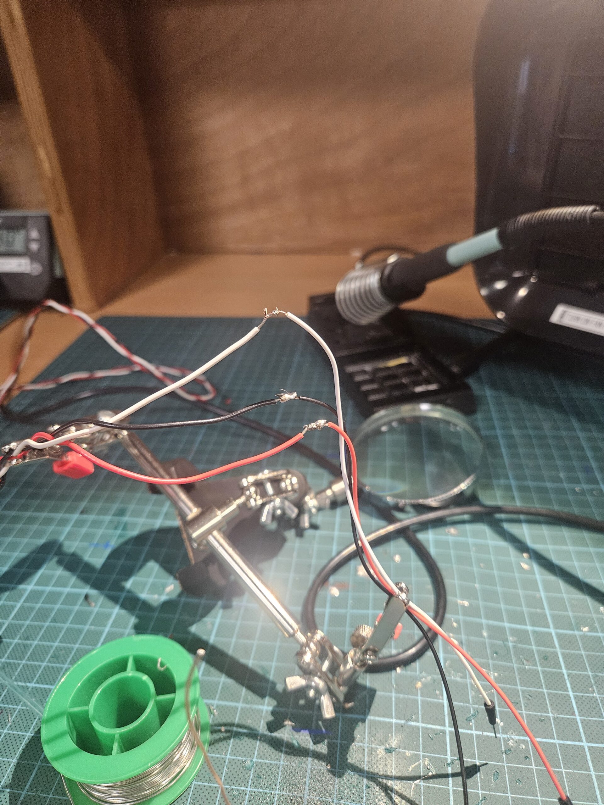
Since these sensors were not from the ardunio kit, I had to solder wires to the sensors as well as for the neo pixels. Thankfully, I was able to get used to soldering towards the end.
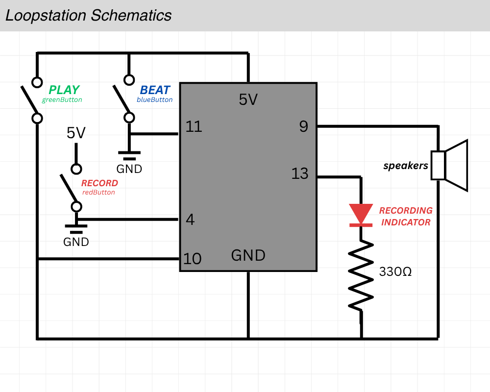
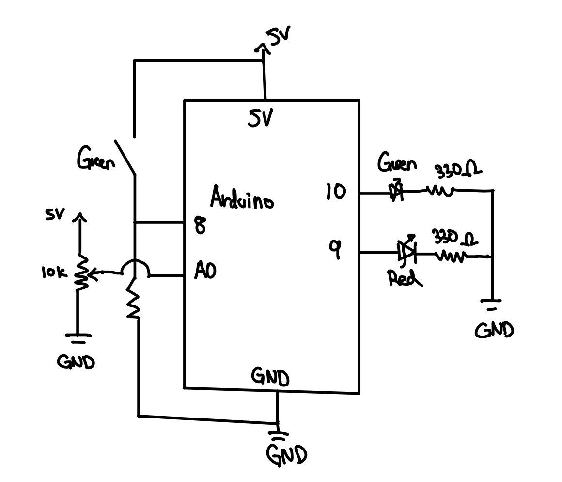
Schematic

Usage of AI
I received help from AI when displaying the memes.

function showGifForCount(count) {
  // Remove previous gif element if any
  if (gifElement) {
    gifElement.remove();
    gifElement = null;
  }

  let url = pickGifForPeopleCount(count);
  if (!url) return;

The memes were not made by me. They were all saved from a website called tenor.com.
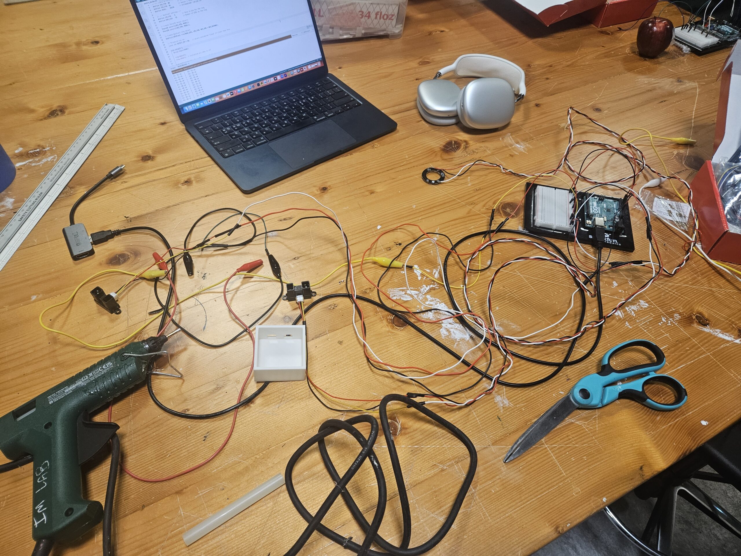
Future Improvement
One major improvement is the cable management. In the current prototype, the wiring between the sensors, microcontroller, and LED ring is exposed, which makes the setup look unfinished and less polished. A future version could incorporate a more integrated system and internal routing channels to hide the wires and create a cleaner presentation.

Final Project Proposal

I was looking for a room in Baraha to get some work done. However, to check some of the rooms there, I had to manually open the doors to see if they were occupied or not. I found the whole process inefficient, since I had to apologize if the room was occupied. The experience was embarrassing, and I was sure there were better ways to avoid it from happening.

So I decided to build my final project based on this idea: a detection machine that lets people know if the room is occupied or not. I found further inspiration from the parking lights installed in some of the malls in Abu Dhabi. There are lights on top of a parking space, and those lights display colors depending on the availability of the space.

At first, I thought using ultrasonic sensors would work. The idea was to have a sensor installed on the door to check if someone walks across the doorway: if they do, activate the light. However, ultrasonic sensors spread in an arc, so they may cause more errors than I expect. Next, I considered using PIR sensors that detect motion and heat. This is a good approach, but since PIR detects only movement, there are issues when people inside do not move: if they sit still and work on their projects, the sensor would assume the room is empty. This defeats the whole purpose of the project.

So for my sensors, I decided to use IR beam-break sensors. It is a single-line sensor that triggers when something gets in the way, so I thought it would be perfect for this project. If I have two of those sensors, I would also be able to determine whether a person enters or exits the room, allowing me to turn the LED on or off. It would be better to have the IR beam sensor installed at the door and a PIR motion sensor installed inside the room for a two-way detection system to ensure fewer errors, but cost-wise, I found that it was not worth having two sensors. I want to buy the sensors so that I can keep the project for my own use without having to return it later.

For the display, I will either order an LED panel or just use a circular LED display to show the status. Universal language such as red light means it is occupied, and green light means that the room is available. I can get more creative and use LED panels to show art installations, which would make it look more like an interactive media project.

Week 10 – Reading Reflection

Reading “Making Interactive Art” made me realize what I created for this week, needs prior explanation before the user can figure out what the device is about. The buttons I made do not have any signs or words attached so the users will need some time to process and play around witht he project before realizing that what I made is a beat memorizer. However, since I took account for possible actions that the user might do, the system won’t crash. I can essentailly, set the stage, shut up ad listen to what the user will do when given my project. In those terms, I can say that I created a successful project that follows what the reading describes.

For physical computing reading, I was able to relate to many of his projects but especially “Things you yell at”. It reminded me of my midterm project because it also used voices to control the system. Pitch detection and voice recognizition is hard at first, but the result is worth the process.

Week 10 – Musical Instrument

We decided to create a beat memorizing machine. A simplified version of the loop machine used in beat creation. Essentially, we have button to record the beat, button used to tap the beat and a button used to play the recorded beat.


Concept (With Visuals) 

After we planned what we wanted to do, I decided to visualize the project first before designing it.

The red button would be to start/stop the recording process. A red LED would indicate whether it was currently recording.

The blue button would be there for the user to tap in their beat.

When you are done with your beat, you can save it by clicking the red button once again. You can see whether it was properly stopped by the indicator turning off. Then you can press the green button to play your recorded beat.

Schematics & Planning – Hubert

Before we started connecting metal to metal, I made a schematic to quickly map out everything we needed to connect.

Code & Difficulties Encountered 

There are 3 main parts to the code. 

The first is figuring out debouncing logic, which is used to remove the state when the system is bouncing between true and false when the switch is pressed. The second part is playback, actually playing back the recorded soundLastly, the third which is the hardest part: finding how to store the beat recording.

I’ll start by explaining the hardest part first, which is storing the beat recording.
The beat recording logic works by tracking the time of each button press and release while the device is in recording mode. Every time the beat button is pressed, the program calculates the gap since the previous press (gap = now – tRef) to capture the spacing between beats. When the button is released, it measures the duration the button was held (dur = now – lastPressTime) to record how long that beat lasted. Both values are stored in arrays (gaps[] and durs[]), building a timeline of when each beat starts and how long it plays. Figuring out this logic was the most difficult part.

uint32_t clampToZero(long x) { //used in playback function when sometimes each beat is pressed too quickly and this is used to remove negative timings
  if (x > 0) {                            //for example, to find the silence between each beat, gap[i] represents time since previous press, durs[i-1] is how long it was held
    return static_cast<uint32_t>(x);      //we do gap[i] - dur[i-1] to find the silence between the notes, but when its sometimes pressed very quickly this value becomes negative
  } else {                                //since in playback, we cant delay negative, this is to prevent that
    return 0UL;
  }
}

void playback() {     
  if (beatCount == 0) {   //if nothing is recorded exit
    return;
  }
  noTone(speaker); //turn speaker off before we play
  delay(120);       //added delay to make sure nothing is cut off

  for (uint16_t i = 0; i < beatCount; i++) {  //loop through recorded beat
    uint32_t waitMs = gaps[i];

    if (i > 0) {
      long corrected = static_cast<long>(gaps[i]) - static_cast<long>(durs[i - 1]);   //this basically is the logic to finding the true silence between each beat as explained before
      waitMs = clampToZero(corrected);
    }

    delay(waitMs); //delay by true silence

    //play the tone for the recorded duration
    tone(speaker, freq, durs[i]);

    //let the tone run to completion before stopping it
    delay(durs[i] + 2);
    noTone(speaker);
  }
}

Now onto explaining the playback logic. The playback logic is responsible for reproducing the rhythm that was recorded. It does this by reading through the stored arrays of gaps and durations in order. For each beat, the program first waits for the gap time, which is the delay before the next beat begins and then plays a tone on the speaker for the duration that was originally recorded. Because each recorded gap includes the previous beat’s duration, the playback code subtracts the previous duration from the current gap to get the true silent time between beats. This ensures that the playback matches the timing and spacing of the user’s original input, accurately reproducing both the rhythm and the length of each beat. I had to create a logic to turn negative silence time to positive because sometimes it gave errors when the inputs and the durations of beats were too short. This is explained in depth in the comment section of the code.

void update() {   //ran inside the loop to update button state
  bool reading = digitalRead(pin); //read button

  if (reading != lastReading) { //if reading has changed since last time, record when it changed (it means it maybe bouncing)
    lastDebounceMs = millis();
    lastReading = reading;
  }

  if ((millis()- lastDebounceMs) >debounce) { //if the input has stayed the same for more than 20ms, what I set as accept it as real change
    if (reading != stableState) {
      stableState = reading;

      if (stableState== LOW) {
        pressEvent =true;      //we ontl change pressEvent and release Event only when input stayed same for 20ms
      } else {
        releaseEvent =true;
      }
    }
  }
}

Finally, the debounce logic ensures that each button press or release is detected only once, even though mechanical switches naturally produce rapid, noisy fluctuations when pressed. When a button’s state changes, the program records the current time and waits a short period to confirm that the signal has stabilized. Only if the input remains steady for longer than this debounce delay does the program treat it as a valid press or release event. This filtering prevents false triggers caused by electrical noise or contact bounce, giving the system clean, reliable button inputs for recording and playback control. At first, I didn’t have this debounce logic implemented and had a hard time figuring out why the system sometimes failed to recognize button presses or seemed to trigger multiple times for a single press. Once the debounce logic was added, the button responses became stable and consistent.

Week 9 – Arduino: analog input and output

Today’s class went over some of the questions I had in mind in creating the circuit and I was able to complete the assignment.

I made a circuit that took in two inputs, green switch and potentiometer. The output is displayed with two led lights: green and red.

int greenPin = 10;    
int redPin   = 9;     
int buttonPin = 8;    
int potPin    = A0;

void setup() {
  pinMode(greenPin, OUTPUT);    //two outputs led
  pinMode(redPin, OUTPUT);
  pinMode(buttonPin, INPUT);   //Input for button 

  digitalWrite(greenPin, HIGH);   //testing if leds work
  delay(1000);
  digitalWrite(greenPin, LOW);
  digitalWrite(redPin, HIGH);   
  delay(1000);
  digitalWrite(redPin, LOW);
}

void loop() {

  int potValue = analogRead(potPin);               //reading potentialometer value
  int brightness = map(potValue, 0, 1023, 0, 255); //scaling the potentimeter from 0 to 255
  int buttonState = digitalRead(buttonPin);        //when pressed it is set as high

  if (buttonState == HIGH) {      //if button is pressed, turn both lights off
    analogWrite(greenPin, 0); 
    analogWrite(redPin, 0);
  } else {                          //if not pressed, light's brightness is controlled by pot.
    analogWrite(greenPin, brightness);
    analogWrite(redPin, brightness);
  }
}

Basically, by default, the two led light’s brightness is controlled by the potentiometer. When I turn the potentiometer to max voltage, the led lights light up with maximum brightness. Otherwise, if I turn the potentiometer to 0, it means that the voltage becomes 0, hence showing no light.

Another input is the green switch and I made it so that when the button stage is high, meaning that when its pressed, the output becomes , turning the lights off.

This is the sample video:


This is the hand-drawn schematic, that we practiced in class today. Re-drawing it definitely helped.

Schematic Week 9 Handrawn

Week 8 – Creative Switch

For my creative switch project, I decided to use my elbows as the mechanism to turn the lights on and off. I attached copper tape to each elbow, with the ends of the tape connected to the circuit. When my elbows touched, the copper tapes made contact, completing the circuit and turning the light on. Surprisingly, I found that maintaining a steady contact between my elbows was more difficult than I expected. You can actually see in my video that my arms are shaking slightly, as it was challenging to keep them perfectly still while keeping the circuit closed.


Reading Response Week 8

The balance between aesthetics and usefulness has always been a hot topic. My perspective on beauty and productivity is that if something does its job well, that is enough. I used to value productivity more than aesthetics. According to the reading, for a product to be truly beautiful, it “has to fulfill a useful function, work well, and be usable and understandable” (p. 7). I agree with this idea because if a product does not serve its intended purpose, it fails to justify its existence.

However, in reality, this is not always the case. Take Apple, for example. People love Apple products because they are well-designed and undeniably beautiful. Yet, in terms of productivity, they may not always be the most practical option. MacBooks, for instance, perform most of the functions that a laptop should, but they lack a USB port. While users can buy external hubs, many find it inconvenient and would prefer at least one built-in port. Despite this, people continue to buy MacBooks. The success of Apple’s stock market performance suggests that many consumers value aesthetics just as much as, or even more than, productivity.

The next reading, about the code that helped send people to the moon, reminded me of the importance of checking and rechecking every detail. It shows why it is essential to anticipate every possible error, even those that seem unlikely or unnecessary. Launching the P01 program midflight might have seemed like a situation that would never occur, but it did. If Lauren had not accounted for this scenario, the outcome for Jim Lovell and the mission could have been very different.

Midterm Project: OOO – EEE

I made a game before that was controlled with keyboard inputs so this time, I wanted to create a game that used different input.
As I was scrolling through Youtube Shorts to find inspiration of my project, I came across a simple game playable with user’s pitch levels. In the video I watched, the character moved up and forward depending on the level of pitch. With this in mind, I tried making simple programs that took user input.


First, I built a program that detected a specific pitch, in this case “C”. If the user sings the pitch, the block is moved upwards and if the user maintains the same level for certain amount of time, the block permanently moves upwards. I made this because my initial strategy was to make a adventure game where the character travels a 2D map and make certain interactions that triggers things such as lifting a boulder with a certain note. This little exercise allowed me to get familiar with sound input and how I can utilize it in the future.

For my midterm, I decided to create a simple game that uses paddles that move left and right. The goal of the game is to catch the falling objects with these moving paddles. The hardest part about the game was obviously moving the paddles depending on the user’s pitch. At first, the paddles were so sensitive to the point that its movement was all over the place even with a slight input of sound. Adjusting that and making it so that it moves smoothly was the key in my game.

While I was testing for movements, I realized that I was making sounds that resembled a monkey. I was making the sounds OOO for the low volumne and EEE to make high pitched noise. So I came up with a clever idea to make the game monkey-themed with falling objects being bananas and the paddles as monkey hands. It made me laugh thinking that the users would have to immitate monkeys in order to play the game. Also, I added a little feature in the end to replay the sound that the players made while playing my game so that they can feel a bit humilliated while playing the game. I thought this was a great idea to bring some humor in my game. I also had to test this multiple times making the game and had to experience it beforehand.

My game is divided into 4 major stages: start screen, instructions, gameplay, and gameover screen. As explained in class, I utilized the different stages so that resetting was easiler.

The startscreen is the title screen. It has 3 buttons: instructions, play and full screen button. Clicking the buttons make a clicking sound. That is the only sound feature I have since my gameplay is hugely effected by sound. Any background music or sound effects effect how the game is played so I kept it to the minimum. Also, making the game full screen effects the game play, so I had the fullscreen feature to fill everywhere else with black.

Before playing the users can click the instructions page to find out the controls and calibrate their pitch range. I deliberately say to use OOOs and EEEs for the pitches so that they can sound like monkeys. These pitch ranges are adjustable with up and down arrows and are stored in the local storage so that the settings remain even after resetting the game. I also show a live paddle so that the users can see how their voice with move the hands.

Once they hit play, the core loop is simple: bananas spawn at the top and fall; the goal is to catch them with the monkey “hands” (the paddle) at the bottom. I map the detected pitch to x-position using the calibrated min/max from instructions, I clamp the raw frequency into that window, map it to the screen’s left/right bounds (so the hands never leave the canvas), then smooth it. To keep control stable I added a small noise gate (ignore very quiet input), a frequency deadzone (ignore tiny wiggles), linear smoothing with lerp, and a max step cap so sudden jumps don’t overshoot. the result feels responsive without the little movement I had early on. The player scores when a banana touches the hands and loses a life on a miss; three misses ends the round.

When the run ends, the gameover screen appears with the background art, a big line like “you got x bananas!”, and two buttons: “play again” and “did you sound like a monkey?”. during gameplay i record the same mic that powers pitch detection; on gameover I stop recording and let the player play/stop that clip. it’s a tiny feature, but it adds a fun (and slightly embarrassing) payoff that matches the monkey concept.


I’m especially proud of how I handled pitch jumps. early on, tiny jitters made the hands twitchy, but big interval jumps still felt sluggish. I fixed this by combining a few tricks: a small deadzone to ignore micro-wiggles, smoothing with lerp for steady motion, and a speed boost that scales with the size of the pitch change. when the detected frequency jumps a lot in one frame (like an “ooo” to a sharp “eee”), I temporarily raise the max movement per frame, then let it settle back down. that way, small fluctuations don’t move the paddle, normal singing is smooth, and deliberate leaps produce a satisfying snap across the screen without overshooting. Getting this balance right made the controls feel musical.

For future improvements on the game itself, I want to smooth the frustration without losing the funny chaos. Bananas don’t stack, but several can arrive in different lanes at the same moment, and with smoothing plus a max step on the hands, some patterns are effectively unreachable. I kept a bit of that because the panic is part of the joke, but I’d like the spawner to reason about landing time instead of just spawn time, spacing arrivals so that at least one of the simultaneous drops is realistically catchable. I can still sprinkle in deliberate “double-arrival” moments as set pieces, but the baseline should feel fair.

Week 3 – Digital Art

Unlike week 2, which lacked user interaction, I wanted this project to focus on having user interaction project an artwork. However, at the same time I didnt want user to think to much in producing the result. So I arrived at the conclusion of making the user press random keys to produce a sort of a simple artwork.

The artwork I was inspired by is from our video.

I noticed that if I have grids of the canvas with each grid having a random diagonal value, it can produce something like this. Of course, the same direction meant the same color.


The random colors are stored in an array that looks like this:

this.palettes = [
      ["#fefae0", "#606c38", "#bc6c25"],
      ["#0f0f0f", "#e63946", "#f1faee"],
      ["#f1f1f1", "#118ab2", "#ef476f"],
      ["#22223b", "#f2e9e4", "#c9ada7"],
      ["#faf3dd", "#2a9d8f", "#e76f51"]
    ];

The first is for the background of the canvas, the second one is for the left diagonal and the third one is for the right diagonal. I did no mention how to change the colors randomly. Feel free to explore and find out how to change colors. Pressing randomly keys might help.

placeRandomDiagonal() {
    //wait if full
    if (this.gridFull()) {
      return;
    }
    //get randomindex to palce the diagonal line
    const randIndex = floor(random(this.emptyIndices.length));
    const i = this.emptyIndices.splice(randIndex, 1)[0];
    
    //get random direction 1 is left 2 is right diagonal
    const dir = random([1, 2]); 
    //get random strokeWeight
    const w = random(1, 5);
    this.cells[i] = { dir, w };
    //call reset to check if its full
    this.scheduleAutoResetIfFull();
  }

This is the code that I wanted to share. This is the place Random Diagonal function, It first gets the random Index to palce the diagonal lines and chooses the random direction and random stroke weight. At the end the of the function it calls another function which simply checks if the grid is full. If it is, it calls the reset function.

//grid cells are stored in 1D array while canvas is 2D so this is to conver linear index to 2D position
//const x is column number
const x = (i % this.cols) * this.cellSize;
//row number
const y = floor(i / this.cols) * this.cellSize;

//each are multiplied by cell size to get pixel coordinates 
//ex cellsize is 20, col is 5 anat i =7. that means 7%5 = 2 column 2 which is 40, row is at 7/5 = 1 at 20, so index 7 maps to position 40,20


The hardest part about this code was the transition of 1D arrays to 2D canvas. Since the information that stores the grid cells are in 1D array, I had to find a method to map each index to a coordinate in the grid. This is done here, the specifics are explained in the comments.

For future Improvements, I think that making mouse clicks have another action on the artwork. Maybe changing the diagonal lines can make the artwork more interactive. Rather than diagonal, it can try different angles with each mouse click.

Week 3 Reading Response

The reading defines interaction to be a cyclic process in which two actors alternately listen, think, and speak. Building on this, I see a strongly interactive system as one that sustains this cycle in a meaningful way, where the user feels their input is not only received but also interpreted in a way that shapes the system’s future responses. In other words, the system doesn’t just react once, but continues to evolve as the user engages with it. I think of strong interactivity as creating a sense of dialogue, where the user’s actions feel acknowledged and the system “remembers” or adapts over time. However, I don’t think strength alone guarantees a good interaction; too much responsiveness without clarity can overwhelm or confuse the user.

I am in the process of choosing my next interactive project for week 3. While I am still brainstorming, unlike week 2’s project that lacked user interaction, I want to create a project where user’s mouse interaction and possibly keyboard interactivity produces an artistic outcome. For example, I could design the sketch so that keyboard inputs that change the “rules of the system,” such as altering font sizes or styles, to produce something like looks like a digital caligraphy. This would make the sketch feel more like an ongoing exchange rather than a one-time reaction. Instead of static outputs, the artwork would emerge from the combination of system logic and user decisions. The key idea is to create a system where user’s input results in a artistic product. I’ll try to take this idea in a direct matter.