Final Project: Space Explorer

Concept

Many of us are fascinated with space and all the heavenly objects floating around far away from us. Our Earth is one of many objects in space. I wanted to make an interactive environment where we could look at these planets and admire their beauty, while also learning a few facts about them.  Hence, I used WEBGL in p5Js to create a 3D space where I could spawn planets and stars which one can explore.

Implementation

My implementation of the project is divided into p5Js and Arduino, and has very simple controls, aesthetic visuals, with immersive audio.

Interactive Design

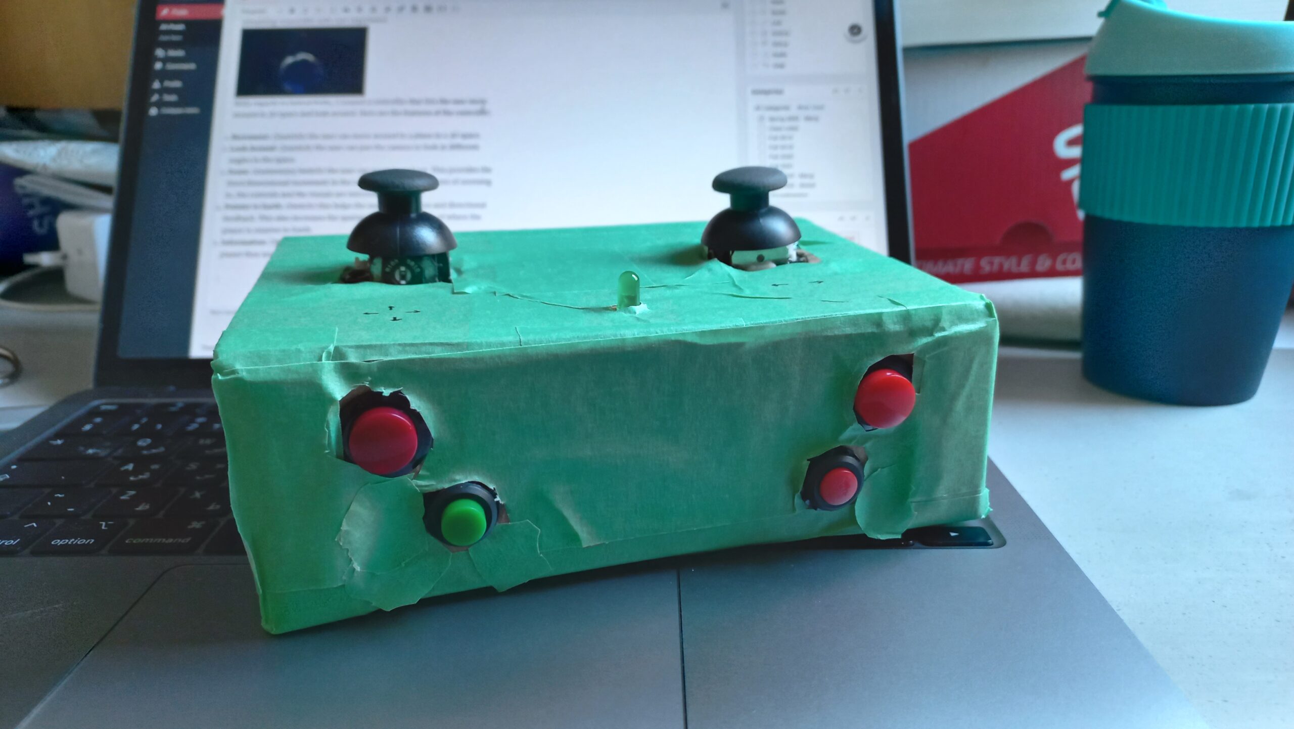
The design of the project is simple. The visual component of the project features a dark space with the nine planets in the solar system (including Pluto) and the Sun. I tried to make it to scale as much as possible but still remaining reasonable with user experience.
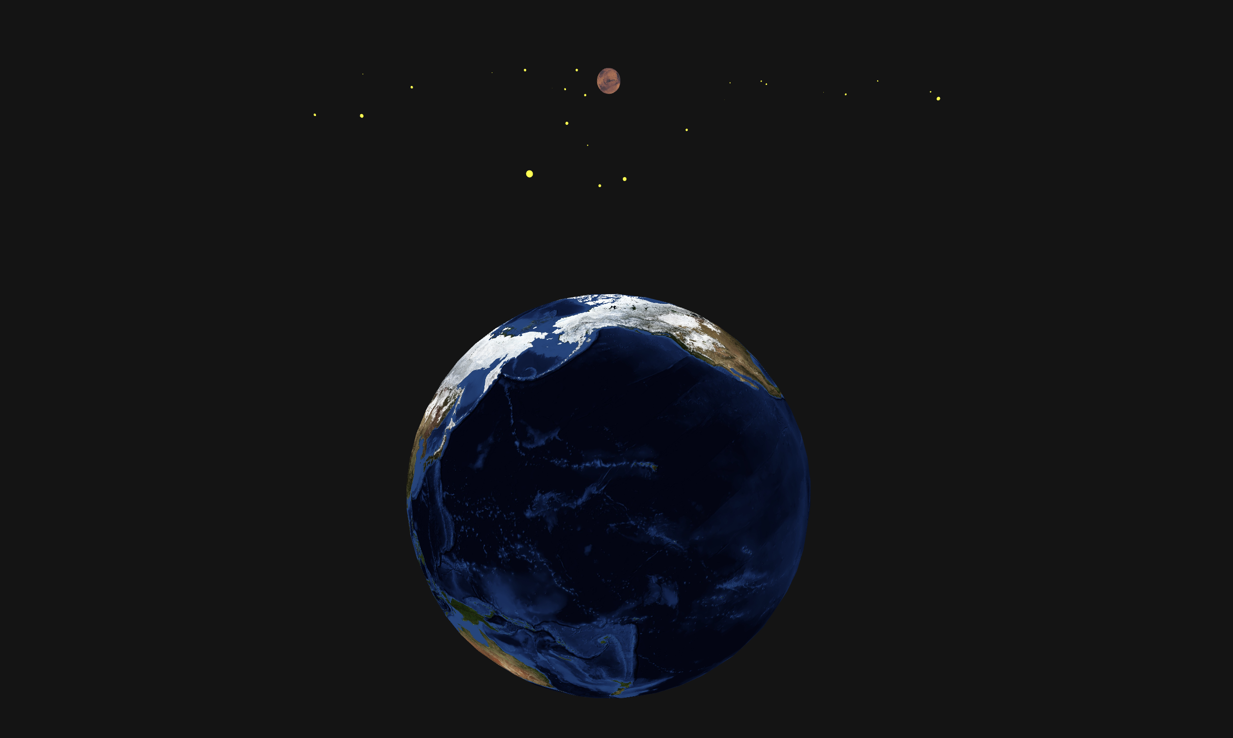
With regards to interactivity, I created a controller that lets the user move around in 3D space and look around. Here are the features of the controller:

  1. Movement: (Joystick) the user can move around in a plane in a 3D space.
  2. Look Around: (Joystick) the user can pan the camera to look at different angles in the space.
  3. Zoom: (momentary Switch) the user can zoom in and out. This provides the third dimensional movement in the z-axis. After a certain point of zooming in, the controls and the visuals are mirrored.
  4. Pointer to Earth: (Switch) this helps the user in navigation and directional feedback. This also increases the spatial awareness; the idea of where the player is relative to Earth.
  5. Information: (Switch) this will provide the user with some facts about the planet they are closest to.
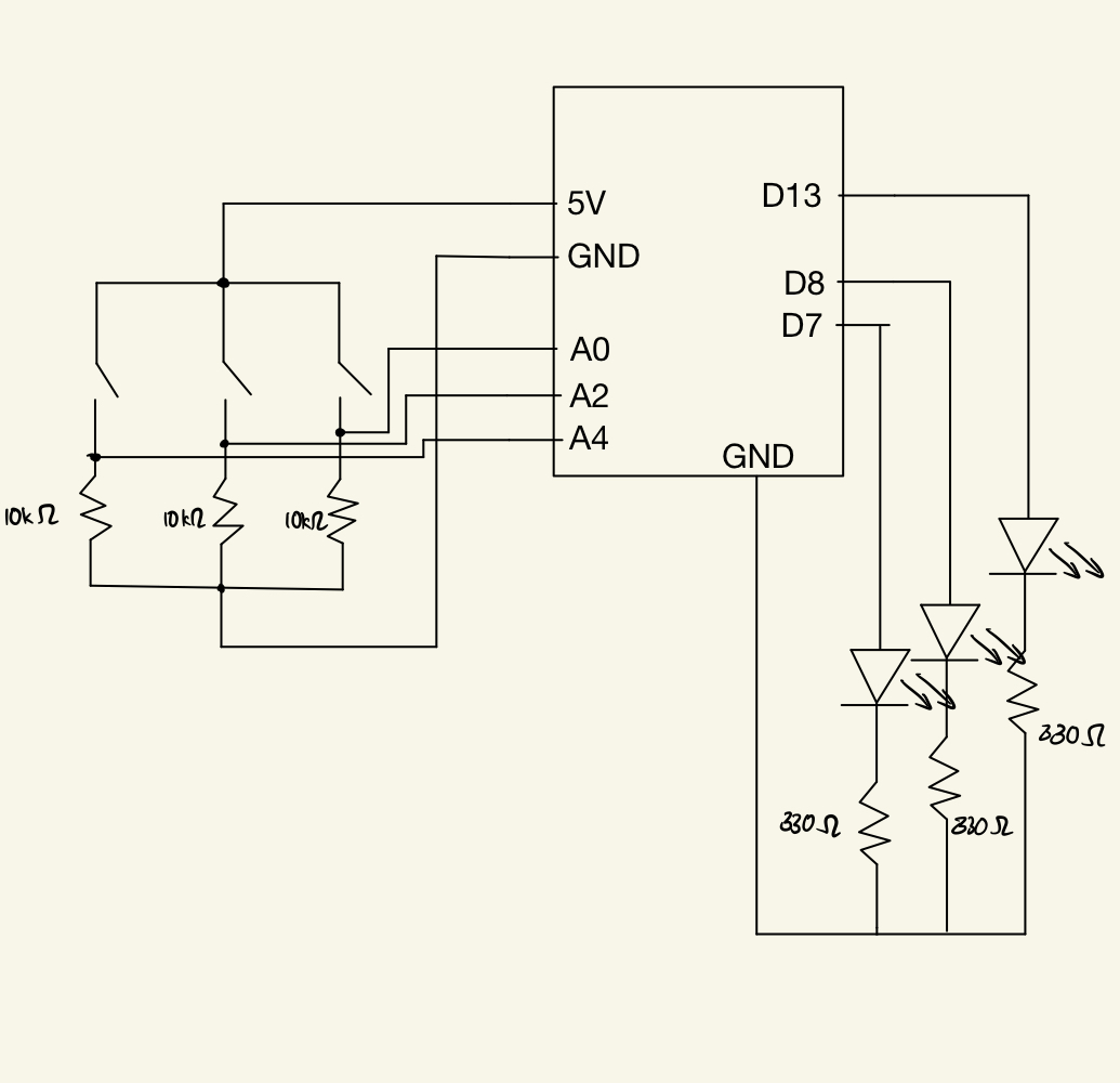
Arduino

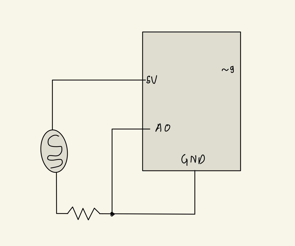
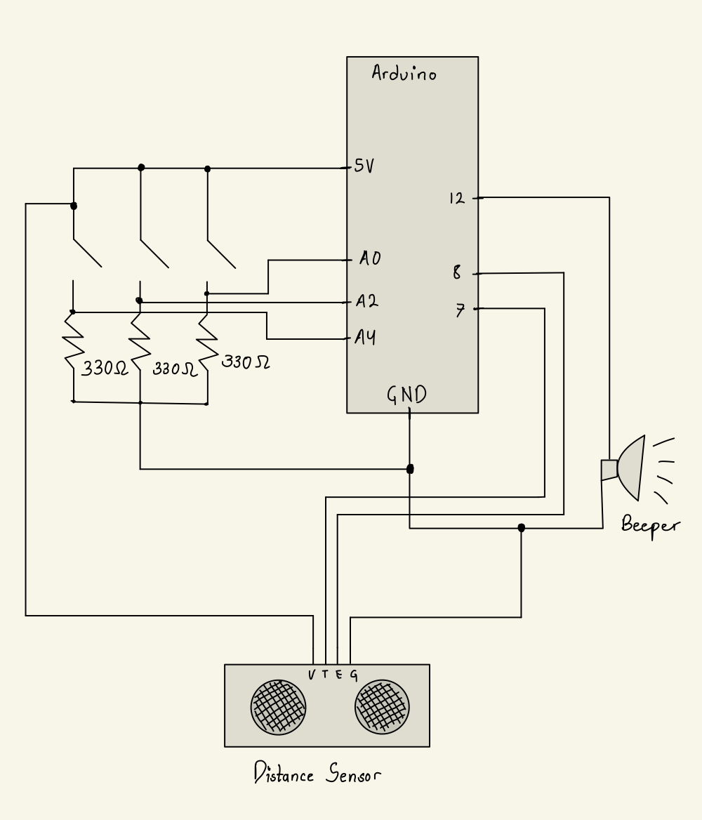
The Arduino provides controller access for the movement and changes in the p5Js. It takes inputs from the joystick and switches, processes it, and sends it to the p5Js as a suitable string of information.

// Movement using joystick
const int x_pos = A0;
const int y_pos = A1;

// zoom in and out
const int z_in = 12;
const int z_out = 11;

// Camera movement
const int camera_x = A5;

// pointer to earth button
const int pointer = 2;

// information about the planet
const int info = 7;

// LED
const int led = 5;

const int n = 7; // number of button inputs the user provides

int send_list[n];

int input_pins[n];

void setup() {
  Serial.begin(9600);

  pinMode(x_pos, INPUT);
  pinMode(y_pos, INPUT);

  pinMode(camera_x, INPUT);

  pinMode(z_in, INPUT);
  pinMode(z_out, INPUT);

  pinMode(pointer, INPUT);

  pinMode(info, INPUT);

  pinMode(led, OUTPUT);

  input_pins[0] = x_pos;
  input_pins[1] = y_pos;
  input_pins[2] = camera_x;
  input_pins[3] = z_in;
  input_pins[4] = z_out;
  input_pins[5] = pointer;
  input_pins[6] = info;

  while (Serial.available() <= 0) {
    Serial.println(0);
    delay(300);
  }
}

void get_user_input() {
  send_list[0] = analogRead(x_pos);
  send_list[1] = analogRead(y_pos);
  send_list[2] = analogRead(camera_x);
  for (int i = 3; i < n; i++) {
    send_list[i] = 0;
    if (digitalRead(input_pins[i]) == HIGH) {
      send_list[i] = 1;
    }
  }
}

void send_input() {
  String to_send = "";
  for (int i = 0; i < n-1; i++) {
    to_send += String(send_list[i]) + ",";
  }
  to_send += String(send_list[n-1]) + "\0";

  Serial.println(to_send);
}

void loop() {
  while (Serial.available() > 0) {
    // get user input and parse to send it to p5js.
    get_user_input();
    send_input();

    // receive response from p5js
    int response = Serial.read();
    analogWrite(led, response);
  }
}

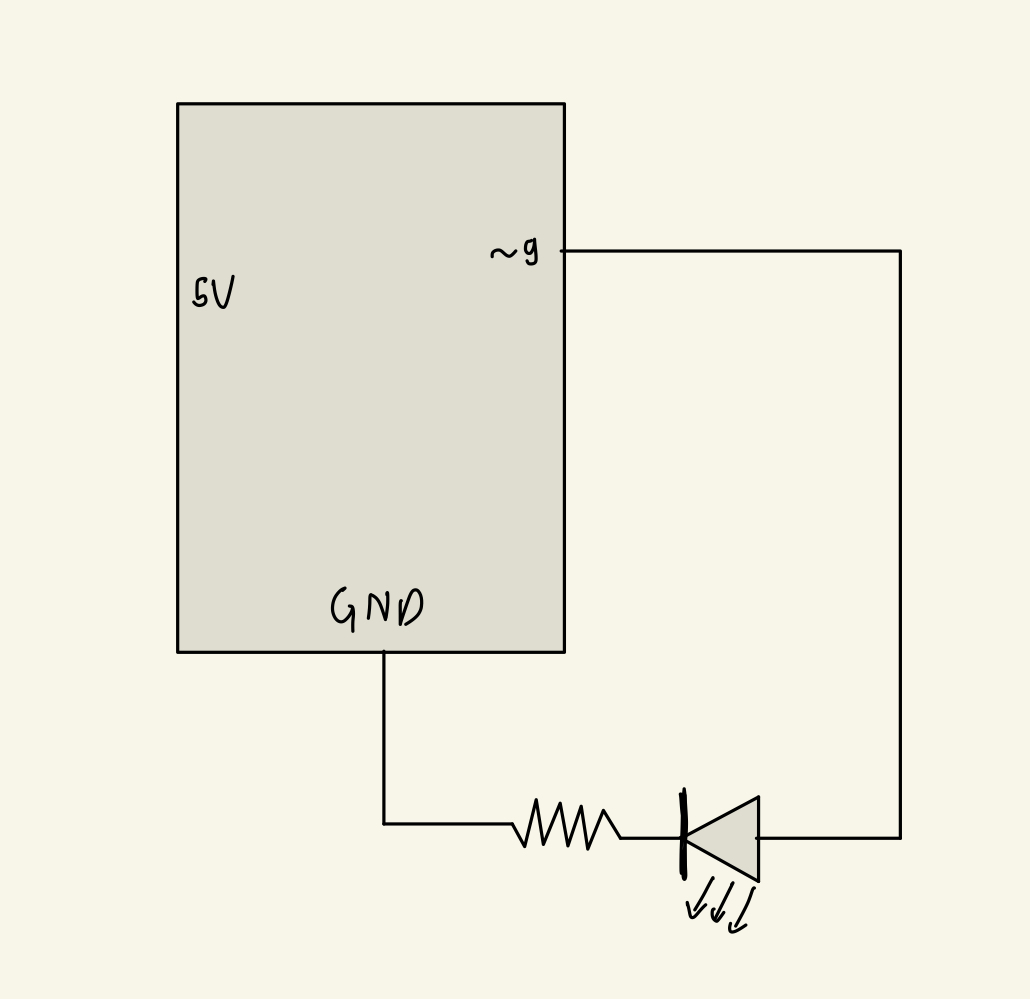
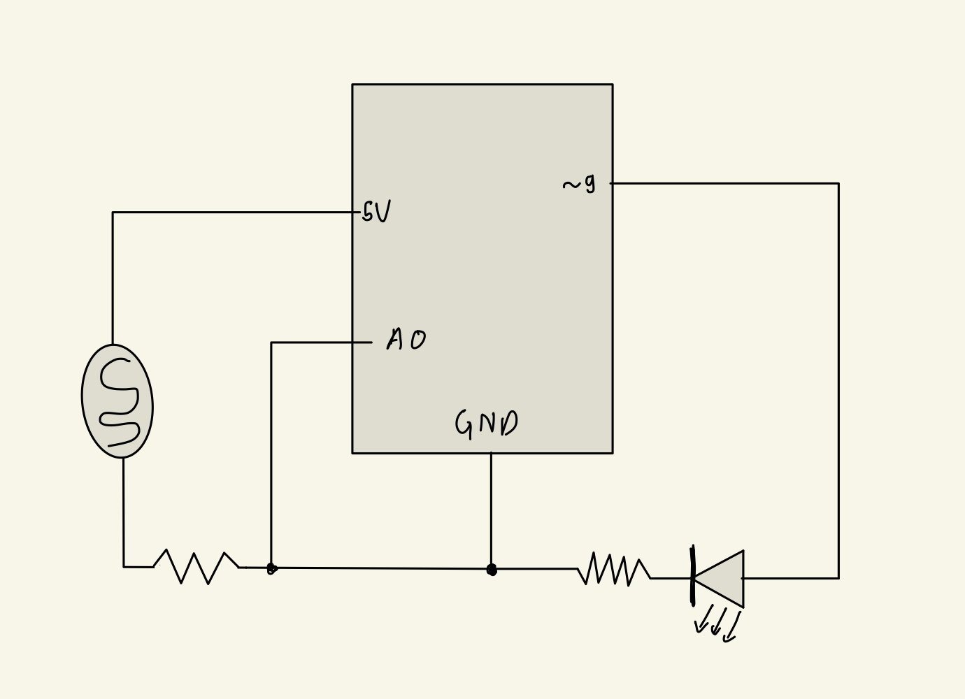
It also receives a confirmation from p5Js that the devices is connected. This can be visually seen from the LED which lights up when the connection is made.

The code first gets all the input and creates an array of them.

p5Js

My project is p5Js heavy. The code lets the user connect to Arduino and receive control information to make changes in the canvas. It creates multiple planets which are basically spheres with different sizes, positions, and textures onto them. Each planet then rotates on its axis and are tilted to some degree. The planets are made stationary relative to the Sun, to make navigation and finding the planets easier.

I used the WEBGL library, to create the 3D space and made the camera movable and responsive of the players movement. This created the effect/ feature of moving in the 3D environment.

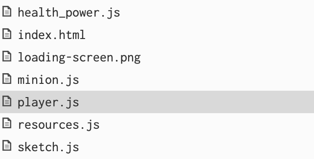
The code features multiple classes: Player, Camera, Sun, Planet, Info, Star which creates most of the functionality and visuals in the project. I separated out the Arduino interaction into a separate file, arduino.js to make debugging easier.

Communication

The communication between Arduino and P5Js is intuitive. When the Arduino senses change in the controller, it extract the values of the state the controller is in. These values are then stored into an the send_list array. All the values in this array is then converted into a string separated by commas. This string is then sent to P5Js for further processing.

void get_user_input() {
  send_list[0] = analogRead(x_pos);
  send_list[1] = analogRead(y_pos);
  send_list[2] = analogRead(camera_x);
  for (int i = 3; i < n; i++) {
    send_list[i] = 0;
    if (digitalRead(input_pins[i]) == HIGH) {
      send_list[i] = 1;
    }
  }
}

void send_input() {
  String to_send = "";
  for (int i = 0; i < n-1; i++) {
    to_send += String(send_list[i]) + ",";
  }
  to_send += String(send_list[n-1]) + "\0";

  Serial.println(to_send);
}

The P5Js then receives this string, and parses it to retrieve all the individual values of all the input devices in the controller. These are then stored in separate variable and used to control the objects on the canvas .

function readSerial(data) {
  if (data != null) {    
    
    // get the information from the arduino
    let nums = data.split(",");
    let len = nums.length;
    
    // parsing the received string to get the useful numbers
    let x = 0;
    for (let i = 0; i < len; i++) {
      user_input[x] = parseInt(nums[i], 10);
      x++;
    }
    
    // continuing the conversation between p5js and arduino
    writeSerial("10");
  }
}

After the information is received, P5Js then sends in a confirmation to Arduino to send in more information. This confirmation also determines the brightness of the LED which lights up when P5Js reciprocates back to the Arduino.

Code I am proud of

The hardest part of the entire project was to figure out the movement in 3D space. I had to first learn the orientation of the camera, then move objects using some arrow keys, and make the movement consistent with where the camera was looking at.

This was very confusing. The problem was, when you move without incorporating the camera into the movement, you would always move the same way, no matter where the camera is pointing towards. For instance, you press UP arrow to move forward. Then you change the camera angle to look behind. When you press UP arrow again, instead of you moving forward, you would move backward.

This problem was overcome by having an angle attribute to the player which would map to the camera as such:

class Camera {
  constructor() {
    // distance between the camera and the virtual player (invisible)
    this.distance = 400;
  }
  
  // creates the camera and determines the position, where the camera is looking at and at what orientation.
  make() {
    camera(this.distance * cos(player.angle) + player.pos.x, this.distance * sin(player.angle) + player.pos.y, this.distance/2, player.pos.x, player.pos.y, player.pos.z, 0, 0, -1);
  }
}

Notice in the above code, the angle is an attribute to the player. It controls where the camera is looking at and where the player moves, as seen in the code below.

// we are in the move() function in the Player class
this.pos.x += move_mag * cos(theta + this.angle - PI/2);
this.pos.y += move_mag * sin(theta + this.angle - PI/2);

Credit: I got the idea of the solution through videos of JS64 Youtube Channel.

Future Improvement

There are a lot of things that I could do with this project. I realised that this project is sort of incomplete, although it serves it purpose of being educational, interactive, and aesthetically pleasing. However, to make it more engaging, I could turn it into a game where, I introduce a character who has to search for more inhabitable planets in the vast expanse of space. I could also link it with my Midterm game, as the theme of space travel is similar.

This project only incorporates the solar system, albeit not entirely since it lacks asteroids, moons and comets. I could expand it more to have more planets and better the spatial awareness so that the player is not lost.

Week 14: User Testing

For my latest version of the final project, Aditya was my user tester. He had seen my project before, but had never used to the controls from the Arduino. My Arduino provides navigation controls for the space exploration in p5Js. I did not say what each controls did, and had him figure out on his own.

Feedback

I received some very useful feedback from Aditya. He did take some time to figure out the controls,  but he commented that the movement was “smooth”.

He liked the visuals and the overall project. However, he also pointed out some improvements I could make.

  1. He suggested I add some kind of music in the background so that the user is engaged and immersed.
  2. The movement was pretty slow and would eventually loose user’s interest.

By observing Aditya, I learnt that his previous experience with controllers, much like mine (similar functionality to X-Box controller),  was making it confusing for him to grasp the movement on screen. There is not much I could do to fix this issue, except let him get the hang of it.

Week 13: Final Project User Testing

Project Concept

I changed my Final Project idea from the LED simulation to a space exploration simulation. This project enables user to interact with the p5js console using the Arduino controlled input devices. Through various buttons (subject to change), the user can navigate through space and explore various planets. The project features a aesthetic interface with liberty for the user to move around in space and explore. As of now, the user can only see the nine planets in the Solar System (including Pluto) and the Sun.

User Testing

Jun Lee and my roommate were my user testers (featured in the video: Jun). They had some difficulty navigating the buttons as they were not labelled, but they quickly learned the mechanic looking at what each of the buttons did. They were able to navigate the space quite easily after a few seconds of trying. The project is still not complete, so the only thing the players can do is move around and admire the heavenly objects and their surface mappings.

Areas that are working well

The navigation is working quite well. I had to adjust where the camera moves (spatial positioning) relative to where it is pointing, such that the left, right, forward, and backward movement are not static and can change depending on where the player is looking at.

There are a lot of areas that need improving. One of them is positioning. Since the background is completely back, it is hard to tell where the player is in space and where he could find planets. I tried adding in a pointer to the Earth, such that the player is not lost and can come back home anytime.

Another thing that needs improvement is the purpose of the project. I want this project to be educational, and at the same time adventurous and fun as the player explores various planets and stars.

Parts I had to explain

I had to explain what the project is and what it does, which is natural and necessary. However, for the controls, I did not explain anything, but the users caught up on it pretty quickly. I had to say what planet they were looking at when they explored, but this can be fixed with a pop-up on screen about such information.

Week 12: Final Project Proposal Revision

Concept

In light of the complexity of my initial plan in making a canvas made of LEDs to let the user draw, I decided to simplify my Final project. The former idea required a lot of LEDs which can not all be supported simultaneously by the Arduino Uno. Thus, I am restricting to a small number of LEDs to bring my project to fruition.

I am planning on two things:

  1. Visual Memory: I will use a 4×4 LED grid to blink LEDs in some pattern. The user is then required to repeat the pattern onto the p5Js console in order to win. This game will increase in difficulty as the user clears the levels.
  2. Text Marquee: On the same 4×4 LED grid, I will create a test marquee which would show text that the user enters onto the p5Js console.

Implementation

Arduino

All the LEDs will be controlled by the Arduino, however, the behaviour of the Arduino will change between the two modes:

  1. For the memory game, the Arduino will generate random co-ordinates which correspond to the LED, and send them to p5Js. It will then wait for further command that instructs it to either repeat the pattern again, or create a new pattern. The difficulty level of the game can be changed with a button or a sensor hooked up to the Arduino.
  2. As for the text marquee, the Arduino will wait for the text the user types and converts it to an array of co-ordinates corresponding to the LED which should be lit up to display that text/letter.
P5Js

The p5Js will incorporate all the user interactivity:

  1. It will provide with a gaming interface for the memory game. It receives the co-ordinates of the LED which it will parse to its gaming screen to register if the user is correct or wrong. It will also send a signal to the Arduino to change the pattern or repeat the pattern
  2. For the text marquee, the p5Js is used as an input device for sending text to the Arduino to later be printed on the LEDs.


Week 11: Final Project Proposal

Concept

For the final project I wanted to do something with drawings and LEDs. So I went with the simple idea of transferring a drawing in p5Js to outputs in LED patterns. I will play around with what other features I could add such as adding colour, brightness (using the alpha in p5Js), gradients, and more.

The project is aimed at entertaining the user, through lightings and real-time feedback as they explore the potential of controlling LEDs through drawing something on the screen.

Implementation

For the user input of the drawings, I will use p5Js and prompt the user to draw something onto the canvas, providing them with colour options. I am also exploring the idea of taking a real-time picture of them and showing their silhouettes through the LED patterns.

As for the physical LED pattern, I will be using Arduino to map the pixels onto their corresponding LED. It will not be a one-to-one mapping as it would take an absurd amount of LEDs otherwise. For the latter idea of a real-time picture, I am planning on roughly mapping their outlines onto the LED.

Week 11 – in class exercises – Sarthak and Yerk

Exercise 1

Scheme: 

Code:

let xVal = 0; //initializing the X value for the position 

function setup() {
  createCanvas(640, 480);
}

function draw() {
  background(230);
  if (!serialActive) {
    text("Press Space Bar to select Serial Port", 20, 30);
  } else {
    // draw an ellipse
    ellipse(xVal, height/2, 100, 50); //giving the ellipse the value of the x position initialized above

  }
}

function keyPressed() {
  if (key == " ") {
    // important to have in order to start the serial connection!!
    setUpSerial();
  }
}

function readSerial(data) {
  if (data != null) {
    xVal = map(data, 0, 500, 0, width); //mapping the values received from the photosensor to control the X position of the ellipse 
    console.log(data);
  }
}
const int pSensor = A0;

void setup() {
  pinMode(pSensor, INPUT);
  Serial.begin(9600);
}

void loop() {
  int val = analogRead(pSensor); //initializing the value received from the sensor 
  Serial.println(val); //sending the value of the sensor to p5js
}

Video:


Exercise 2

Scheme: 

Code:

//p5js code

let change = 0; //initializing the variable for the distance between two consecutive center points of the rectangle
let previousX; //initializing the variable for the X dimension of the previous position of the rectangle 
let previousY; //initializing the variable for the Y dimension of the previous position of the rectangle 

function setup() {
  createCanvas(640, 480);
  textSize(18);
  textAlign(CENTER);
  previousX = 0;
  previousY = 0;
}

function draw() {
  background('red');

  if (!serialActive) {
    fill('white');
    text("Press Space Bar to select Serial Port", width/2, height/2);
  } else {
    fill('white');
    rectMode(CENTER);
    rect(mouseX, mouseY, 200,200); //controlling the center of the rectangle with the mouse 
    fill('black');
    text("Move as fast as you can to control the brightness of the LED", width/2,20);
    getChange(); //calling the function that will track the distance between the two consecutive positions of the rectangle 
  }
  
}

//calculating the distance of two consecutive rectangle positions 
function getChange(){ 
  change = floor(sqrt(pow((mouseX - previousX),2) + pow((mouseY - previousY),2)));
  previousX = mouseX;
  previousY = mouseY;
}

function keyPressed() {
  if (key == " ") {
    setUpSerial();
  }
}

function readSerial(data) {
  if (data != null) {
    console.log(change);
    writeSerial(change); //sending the value of the distance two control the LED brightness 
  }
}
const int led = 9;

void setup() {
  // put your setup code here, to run once:
  pinMode(led, OUTPUT);
  Serial.begin(9600);

  while (Serial.available() <= 0) {
    Serial.println("0");
    delay(300);
  }
}

void loop() {
  while (Serial.available()) {
    int brightness = Serial.parseInt(); // read the incoming data as an integer
    analogWrite(led, brightness); // set the LED brightness based on incoming data
    Serial.println();
  }
}

Video:

Exercise 3

Scheme: 

Code:

//p5js code

let velocity;
let gravity;
let position;
let acceleration;
let wind;
let drag = 0.99;
let mass = 50;

let ard_wind = 1; //initializing the wind speed 
let bit;

function setup() {
  createCanvas(640, 360);
  position = createVector(width / 2, 0);
  velocity = createVector(0, 0);
  acceleration = createVector(0, 0);
  gravity = createVector(0, 0.5 * mass);
  wind = createVector(0, 0);
  bit = 0; //initializing the value for the LED
}

function draw() {
  background(255);

  if (!serialActive) {
    text("Press Space Bar to select Serial Port", 20, 30);
  } else {
    applyForce(wind);
    applyForce(gravity);
    velocity.add(acceleration);
    velocity.mult(drag);
    position.add(velocity);
    acceleration.mult(0);
    ellipse(position.x, position.y, mass, mass);

    if (position.y > height - mass / 2) {
      velocity.y *= -0.9; // A little dampening when hitting the bottom
      position.y = height - mass / 2; 
      bit = 1; //lighting up the LED upon collision with "the ground"
    } else {
      bit = 0; //turning off the LED when the ball is not touching "ground"
    }
  }
}

function applyForce(force) {
  // Newton's 2nd law: F = M * A
  // or A = F / M
  let f = p5.Vector.div(force, mass);
  acceleration.add(f);
}

function keyPressed() {
  if (keyCode == LEFT_ARROW) {
    wind.x = ard_wind * -1; //when left arrow is pressed, the velocity of the wind attains a negative value and the ball moves to the left 
  }
  if (keyCode == RIGHT_ARROW) {
    wind.x = ard_wind; //when the right arrow is pressed, the velocity of the wind attains a positive value and the ball moves to the right 
  }
  if (keyCode == DOWN_ARROW) {
    mass = random(15, 80);
    position.y = -mass;
    velocity.mult(0);
  }
  if (key == " ") {
    // important to have in order to start the serial connection!!
    setUpSerial();
  }
}

function readSerial(data) {
  if (data != null) {
    let sen = bit + "\n";
    writeSerial(sen); //sending the values to light up or turn off the LED
        
    ard_wind = map(data, 0, 300, 0, 10); // mapping the data received from arduino to a sensible range for the wind velocity 
    console.log(ard_wind);    
  }
}
const int led = 12;
const int photoSensor = A0;

void setup() {
  // put your setup code here, to run once:
  Serial.begin(9600);
  pinMode(led, OUTPUT);
  pinMode(photoSensor, INPUT);

  while (Serial.available() <= 0) {
    Serial.println(0);
    // delay(300);
  }
}

void loop() {
  while (Serial.available() > 0) {
    int bit = Serial.parseInt(); // read the incoming data as an integer
    digitalWrite(led, bit); // set the LED brightness based on incoming data

 //send the values of the photosensor to p5js
    int val = analogRead(photoSensor); 
    Serial.println(val);
  }
}

Video:


Home Work 10 – Sarthak and Yerk (AutoTune)

AutoTune

Concept:

For this project, we were inspired by AutoTune. AutoTune allows you to take a certain musical key and make sure all the notes are aligned within that key, thereby perfecting the sound.

Execution: 

For the circuit, we used a buzzer, three switches, and a distance sensor. Initially, we used the key of C major and the note C as our reference point. Having calculated the mathematic relationships that exist between notes in a major key, we assigned different intervals of distance to different notes for that key. For instance, if the user’s hand is 0-5 cm away from the sensor, the circuit will play a C note. If the hand is 5-10 cm away, the circuit will play a D note. This method does not let notes that do not belong in the C major key to be played, which perfects the sound of the board. Just like AutoTune.

When the yellow button is pressed, the key that is being played is transposed up a half step. So if the user is playing in a C major key, once the yellow button is pressed, the user will now play in D flat major. The green button executes the opposite effect – it transposes the key down a half step. If a user is playing in F major, upon pressing the button, they will play in E major.

Finally, if the blue button is pressed, the user will now play in the natural minor key, completely changing the mathematical relationships that underlie the notes. For instance, if the user was playing in the G major key, once they press the button, they will hear the G minor key. This process goes the other way around: if the button is pressed again, the user will go back to the major key.

Circuit: 

Code:

int note_c = 262;

const int beeperPin = 12;
const int trigPin = 7;
const int echoPin = 8;
const int yellowSwitch = A0;
const int greenSwitch = A2;
const int blueSwitch = A4;

const int division = 5;

int flag = 1;

// this is the number of notes in an octave
const int num = 8;

int all_notes[num];

int getDistance() {
  // this bit of code was taken from https://howtomechatronics.com/tutorials/arduino/ultrasonic-sensor-hc-sr04/

  // calculating the distance between the user and the sensor
  digitalWrite(trigPin, LOW);
  delayMicroseconds(2);

  digitalWrite(trigPin, HIGH);
  delayMicroseconds(10);
  digitalWrite(trigPin, LOW);

  int duration = pulseIn(echoPin, HIGH);
  int distance = duration * 0.034/2;

  Serial.print("Distance: ");

  return distance;
}

int getNote(int distance) {
  int index = distance / division;

  return all_notes[index];
}

void makeMajorKey() {
  // making an array of all the notes in an octave given in the major key.
  all_notes[0] = note_c;
  int n = 1;
  for (int i = 1; i < num; i++) {
    // the third and seventh note change is a half step.
    if ((n % 3 == 0 && n % 6 != 0) || n % 7 == 0){
      all_notes[i] = all_notes[i-1] * pow(2, 1.0/12.0);
    } else {
      all_notes[i] = all_notes[i-1] * pow(2, 1.0/6.0);
    }
    n++;
  }
}

void makeMinorKey() {
  // making an array of all the notes in an octave in the minor key.
  all_notes[0] = note_c;
  int n = 1;
  for (int i = 1; i < num; i++) {
    // the second and fifth note change is a half step.
    if ((n % 2 == 0 && n % 4 != 0 && n % 6 != 0 && n % 8 != 0) || n % 5 == 0){
      all_notes[i] = all_notes[i-1] * pow(2, 1.0/12.0);
    } else {
      all_notes[i] = all_notes[i-1] * pow(2, 1.0/6.0);
    }
    n++;
  }
}

void setup() {
  pinMode(beeperPin, OUTPUT);
  pinMode(trigPin, OUTPUT);
  pinMode(echoPin, INPUT);
  pinMode(yellowSwitch, INPUT);

  Serial.begin(9600);

  makeMajorKey();
}

void loop() {
  // PipeLine
  // get the distance of an object
  int distance = getDistance();
  if (distance <= division * num) {
    // create note for that distance
    int note_to_play = getNote(distance);

    // play the note
    tone(beeperPin, note_to_play);

    // switch to transpose up
    int yellow_state = digitalRead(yellowSwitch);

    // switch to transpose down
    int green_state = digitalRead(greenSwitch);

    // switch to toggle between major and natural minor key
    int blue_state = digitalRead(blueSwitch);

    if (yellow_state == HIGH) {
      // transposing the key of the instrument a half-step up, when the switch is clicked.
      note_c = note_c * pow(2, 1.0/12.0);
      makeMajorKey();
    }

    if (green_state == HIGH) {
      // transposing the key of the instrument a half-step down, when the switch is clicked.
      note_c = note_c / pow(2, 1.0/12.0);
      makeMajorKey();
    }

    // changes major key to natural minor key and vice versa.
    if (blue_state == HIGH) {
      if (flag == 1) {
        makeMinorKey();
        flag = 0;
      } else {
        makeMajorKey();
        flag = 1;
      }
    }
  }
}

Video:

Future Improvements: 

One of the issues with the current board is that the code may register the clicking of the button as multiple clicks, even if the user had pressed the button once. With the yellow and the green buttons, this leads to a higher or a lower transposition than expected. With the blue button, there are instances when it simply skips over the shift to the minor key because it registers one click as two. In the future, we want to work toward eliminating that inconvenience.

Week 9: Digital Sensor

Concept

With this assignment, I wanted to implement a traffic light system. The system would light up the red, yellow, and green LED in order, and independently if needed. Below is a circuit diagram for the implementation of the traffic light:

Video

Implementation

There are three major features I included in this assignments:

  1. LED and Switch: I implemented the basic light switch, such that the LED lights up when their respective coloured switch is pressed.
  2. Two Switch: When you press two switches at once, their respective LEDs simulate a FizzBuzz pattern as such: Given a starting index
    1. Both LEDs are turned off when index is divisible by 15.
    2. Both LEDs are turned on when index is divisible by 3 and 5.
    3. LEDs alternate to light up when index is numbers other than ones mentioned above.
  3. Three Switch: When you press three switches at once, they simulate a traffic light, such that they oscillate from red -> yellow -> green and back for a couple of times.

Code:

const int red_in = A0;
const int yellow_in = A2;
const int green_in = A4;

const int red_out = 13;
const int yellow_out = 8;
const int green_out = 7;

const int NUM = 5;
int index;

void light_up(int out) {
  digitalWrite(out, HIGH);
  delay(500);
  digitalWrite(out, LOW);
}

void run_fizzbuzz(int out1, int out2) {
  // checking the state of the buttons, so that we do not run the code when the buttons are not pressed
  int red_switch = digitalRead(red_in);
  int yellow_switch = digitalRead(yellow_in);
  int green_switch = digitalRead(green_in);

  while (red_switch == HIGH || yellow_switch == HIGH || green_switch == HIGH) {
    // regular checking for the button press
    red_switch = digitalRead(red_in);
    yellow_switch = digitalRead(yellow_in);
    green_switch = digitalRead(green_in);

    if (index % 15 == 0) {
      digitalWrite(out1, LOW);
      digitalWrite(out2, LOW);
    } else if (index % 3 == 0 || index % 5 == 0) {
      digitalWrite(out1, HIGH);
      digitalWrite(out2, HIGH);
      delay(300);
      digitalWrite(out1, LOW);
      digitalWrite(out2, LOW);
    } else if (index % 2 != 0) {
      light_up(out1);
    } else if (index % 2 == 0) {
      light_up(out2);
    }

    delay(100);
    digitalWrite(out1, LOW);
    digitalWrite(out2, LOW);
    index++;

    if (index > 20)
      break;
  }
}

void setup() {
  // defining the digital output and digital input for the LEDs
  pinMode(red_in, INPUT);
  pinMode(yellow_in, INPUT);
  pinMode(green_in, INPUT);
  pinMode(red_out, OUTPUT);
  pinMode(yellow_out, OUTPUT);
  pinMode(green_out, OUTPUT);
}

void loop() {
  // Code base for the LEDs
  /*
    OBJECTIVE: Simulate Traffic Light
  */

  // reading the switch state
  int red_switch = digitalRead(red_in);
  int yellow_switch = digitalRead(yellow_in);
  int green_switch = digitalRead(green_in);

  // starting index for FizzBuzz
  index = 1;

  // if all of them are pressed, start simulating a traffic light: RED -> YELLOW -> GREEN. Oscillate between these every few seconds
  if (red_switch == HIGH && yellow_switch == HIGH && green_switch == HIGH) {
    // simulate the traffic light

    // this is a blocking function, as no inputs are registered as long at this loop is running.
    for (int i = 0; i < NUM; i++) {
      light_up(red_out);
      delay(100);
      light_up(yellow_out);
      delay(100);
      light_up(green_out);
      delay(100);
    }

  } else if (red_switch == HIGH && yellow_switch == HIGH && green_switch == LOW) {
    // if the red and yellow switch are turned on, run a FizzBuzz algorithm, such that every multiple of 3, 5 or 15 lights of both the LED, while the LEDs oscillate between each other during other iterations
    run_fizzbuzz(red_out, yellow_out);

  } else if (red_switch == HIGH && yellow_switch == LOW && green_switch == HIGH) {
    // if the red and yellow switch are turned on, run a FizzBuzz algorithm, such that every multiple of 3, 5 or 15 lights of both the LED, while the LEDs oscillate between each other during other iterations
    run_fizzbuzz(red_out, green_out);

  } else if (red_switch == LOW && yellow_switch == HIGH && green_switch == HIGH) {
    // if the red and yellow switch are turned on, run a FizzBuzz algorithm, such that every multiple of 3, 5 or 15 lights of both the LED, while the LEDs oscillate between each other during other iterations
    run_fizzbuzz(yellow_out, green_out);

  } else {
    // light up red when red switch is pressed
    if (red_switch == HIGH)
      digitalWrite(red_out, HIGH);  

    // light up yellow when 
    if (yellow_switch == HIGH)
      digitalWrite(yellow_out, HIGH);

    // light up gree when 
    if (green_switch == HIGH)
      digitalWrite(green_out, HIGH);
  }

  // default state
  digitalWrite(red_out, LOW);
  digitalWrite(yellow_out, LOW);
  digitalWrite(green_out, LOW);
}


Improvement

There is probably a better way to implement the circuit, and the code. The Two Switch features only works when you keep on pressing the button, as opposed to pressing them once and letting the code run. However, this is intended such that pressing two buttons simultaneously by mistake does not lead to the user, waiting for the FizzBuzz to end. However, I have made the Three Switch feature, blocking, such that the user waits for the traffic light animation to end in order to provide other inputs again.


Week 8: Unusual Switch

Concept

Since, we had to make a switch that did not require the use of hands, I thought of using wind to switch on the LED lights. The easiest thing to do was to blow onto a metallic strip like aluminium or tin foil, such that the strip would touch another metallic surface to complete the circuit.

This idea of blowing onto something let me develop this project into a device that would act as a spirometer (Fig. below). A spirometer is a device used to test a person’s lung capacity. One would simply blow onto the pipe and try to raise the three balls to the top. The idea of my switch is similar; one would simply blow onto two strips of metallic strip to turn on the two LED lights.

Video

How it Works

I used some copper tapes and joined them together to make two flexible metallic strip. I used a solid metallic sheets such that they stay in place when some wind is applied to it. The idea is to blow onto the copper strip hard enough to light up both the bulbs.

The first metallic strip is thinner and easier to deform, while the second one is relatively thicker and requires more force to make it touch the metallic sheet.

Note: the first circuit lights up the red LED, while the second lights up the yellow.

When a copper strip touches a metallic sheet, they complete the circuit. However, only one copper strip and metallic sheet is associated with one LED light. In other words, the circuit is set up as two parallel circuits as shown in the figure below.

Improvement

The copper strips are set up in such a way that one blocks the wind from the other which only makes it harder to light up the second LED. So, an improvement could be a set-up which does not block wind, but a mechanism which requires more pressured air such that both the lights are lit up.

Week 7: Midterm Project – Endure.io

Concept

You and your friend are space travellers who roam around various planets just for the fun of it. Racing against each other as you explore few planets is a hobby for both of you. One day, however, your spaceship malfunctions and crashes into a nearby planet. Your friend was so far ahead on the race that s/he does not realise you have crashed. You do not get injured in the crash but your spaceship is damage and all the equipments in the spaceship, including your laser gun.

An entire alien civilisation has seen you crash and perceives you as a threat. They are coming to attack you! Defend yourself with a damaged gun that shoots laser on random directions as you collect resources scattered around the planet to repair your ship and hopefully get back to your friend.

Game Dynamics

This is a simple game with simple dynamics:

  1. The player is movable through the arrow keys.
  2. The aliens/minions are not playable characters but follows the player wherever they go.
  3. Resources and Health Regen spawn in random places

I have made the game as simple as possible so that the player is not overwhelmed with all the functionality possible. This is mainly a time based game where the player needs to survive for the longest period of time and collect about 50 resources to win the game. However there is a catch. The resources spawn every 5 or so seconds and you will only have at most two resources dropped at any given moment. Thus, the player can not wait for all the resources to be dropped then collect it, rather the player constantly needs to move around to collect he resources. This is true for the health regeneration power up as well, however, you can have at most three of these at any given moment on screen.

Code I am proud of

The biggest thing that made working on the code easier was dividing the whole code into various different JS files and having them only focus on certain aspect. For instance, I divided the player, minion and weapon class into different JS files to make debugging and understanding the code easier. This also makes the filing structure logical and effective.

The hardest part of the project when either the laser or the minion were to be deleted from the canvas and the game environment after a collision. The problem is simple; when the laser hits the minion:

  1. The minion has to be deleted
  2. The arrow has to be deleted

Despite the simplicity of the problem, it was not easy to overcome. Let’s just look at minions for now. I had to figure out:

  1. what deleting a minion from the game environment meant.
  2. which minion to delete, and how do I know which is the minion in the array that I had to delete

For the first problem, I realised that deleting simply meant that I had to remove the minion from the minions array. This would simply not display a minion object, hence removing it entirely. The next problem I ran into right after implementing the deletion code was that: as the player moves around, the minion that was deleted was not the ones that the laser hit. The deletion of minions appeared to be random. I had my eureka moment, when I realised I had to specify an id for each minion so that I could identify which laser hit (the lasers are also id‘ed) which minion. This way I could delete the specific minion and not break the code.

I decided to id the objects using their indices in the array. This meant that I had to decrease the id of the objects of the subsequent objects in their arrays by 1. This made id reusable and limited to the number of minions in any given instance.

detectLaserHit() {
    for (let i = 0; i < lasers.length; i++) {
      let laser_pos = lasers[i].getLaserPos();
      
      let d = dist(laser_pos.x, laser_pos.y, this.pos.x, this.pos.y);
      
      if (d < this.radius) {

        this.health--;
        if (this.health <= 0) {
          // Notice we delete the minion according to their id and reset the id in the following lines
          minions.splice(this.id, 1);

          // since the minion id is linked to its index in the array, we are decreasing the id of every minion that comes after the minion we killed in the array.
          for (let i = this.id; i < minions.length; i++) {
            minions[i].id -= 1;
          }
        }
        
        lasers[i].sturdiness--; 
        if (lasers[i].sturdiness <= 0) {
          lasers.splice(i, 1);
        }
      }
    }
  }

Problems Encountered:

There are various problems I ran into and here is a list of them:

Note: italics means that I was able to solve them, while bolded text mean I was not.

  1. Sound: I had an error while running the code. The error told me that play() was being called when a new sound file was being loaded. It appeared it was an error with createAudio, which I swapped out with loadSound. Another problem was that my sound was clipping because I put my play function inside the draw function, which was calling the play function multiple times. I had to take play the sound in setup function.
  2. Event called more than once: When suppose we are at time 10 seconds in the game, at this time I call the upgrade_weapons function. This was however being called multiple times in the course of the 10th second. So, I had to use a boolean flag to make sure I was only calling the functions once.
    if (endurance_time % 10 == 0 && upgrade_flipper) {
      upgrade_weapons();
      upgrade_minions();
      drop_health_power_up();
    }
    // stop upgrading when upgraded once
    // flipping the flippler to true once the second has passed.
    if (endurance_time % 10 == 1) {
      upgrade_flipper = true;
    }
  3. Minions movement: The minions move towards the player in a trivial fashion, just changing direction straight towards the player. This creates a line of minions in the x-axis and y-axis relative to the player. I tried adding in randomness to their movement but this. I did randomise the speeds of every minion to minimise this effect, but it is still persistent.

Future improvements:

There are a lot of thing to improve on this game. Firstly the game dynamics itself. I could add in different levels and improve the weapon in different level. I could also implement a controllable weapon where you can roughly aim where to hit (with enough resources, you can repair your weapon). Another improvement could be adding in a boss alien when killed would give me tons of resources. This game could take a multiplayer approach, where my friend finds me and helps me escape the planet.