Tokyo Flight (Final Project by Shota)

Main Concept:

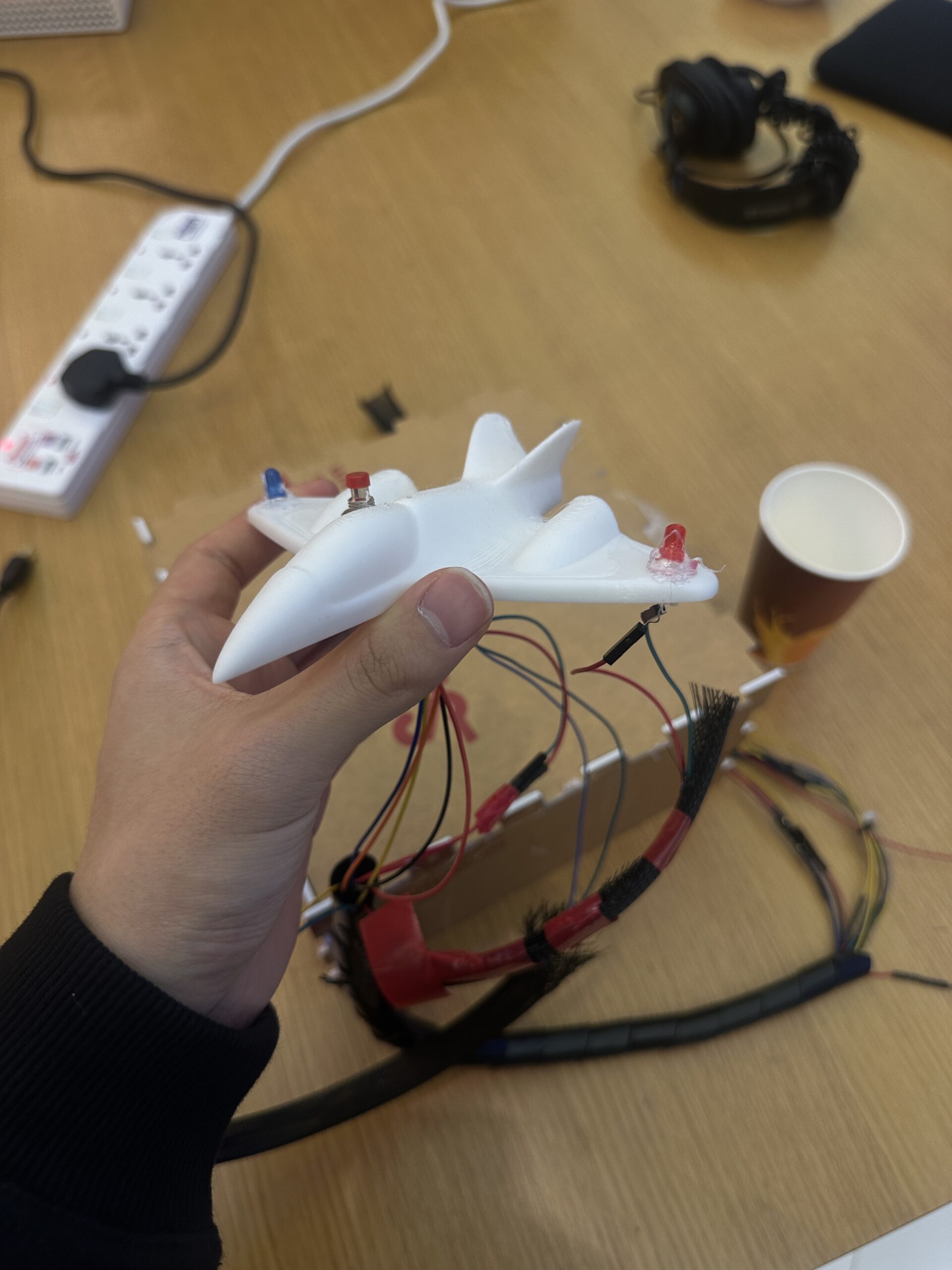
As a super ambitious Ghibli fan, it has always been my dream to step into a Ghibli world, especially The Wind Rises, the film about an aviation engineer during World War II. For this final project, I made my dream come true by creating an interactive game called Tokyo Flight where users can experience flying in the sky and controlling their own plane as a pilot. The game is controlled using a handmade physical airplane that I designed and built with a 3D printer. It includes an accelerometer to measure the plane’s tilt angle, a button to boost its speed, and LED lights that illuminate the airplane during gameplay. The objective is simple: collect as many stars as possible without getting hit by bombs.

Interaction Design:

Tokyo Flight is very interactive due to the effective communication between Arduino and p5. First of all, users control the airplane on the screen using a unique handmade airplane controller. During user testing, people found it very unique and interesting because it made them feel like they were actually flying in the sky, and they had never used this kind of controller before, so I am very proud of it. Furthermore, there is a button on the airplane that users can press to boost the plane’s speed on the screen. There are also LED lights on top of the controller so that users can see when they collect stars, reflecting the actual lights on real airplanes. Overall, the smooth communication between Arduino and p5, along with the unique controller, makes the game very interactive.

P5 Code:

Since my final project is an interactive game, my code uses different game states, and depending on which state the user is in, it displays the corresponding screen and either shows buttons or allows them to play the game. This is exactly what we learned in class before the midterm about using game states to control the flow of the game, so I applied that technique here. I also used the sprite trimming technique we learned in class. This time, however, I struggled to cut out each plane cleanly since the distances were not measured accurately. I tried adding padding, but the current state is the best I could do to make each plane size look consistent. 

// get the width and height of the spritesheet
  let imageWidth = spritesheet.width;
  let imageHeight = spritesheet.height;
  
  // get the number of images in row and col
  let cols = 5;
  let rows = 6;
  let cellWidth = imageWidth / cols;
  let cellHeight = imageHeight / rows;
  
  // some padding between the images
  let padding = 5;
  
  airplaneSkins = [];
  
  // use the template from the class slides 
  // extract each plane from the spritesheet
  for (let row = 0; row < rows; row++) {
    for (let col = 0; col < cols; col++) {
      // get the position and the size of each image 
      let x = col * cellWidth + padding;
      let y = row * cellHeight + padding;
      let w = cellWidth - (padding * 2);
      let h = cellHeight - (padding * 2);
      
      // ensure we don't go outside the image bounds
      x = max(0, min(x, imageWidth - w));
      y = max(0, min(y, imageHeight - h));
      w = min(w, imageWidth - x);
      h = min(h, imageHeight - y);
      
      // extract the image if it is not empty
      if (w > 0 && h > 0) {
        let img = spritesheet.get(x, y, w, h);
        airplaneSkins.push(img);
      }
    }
  }


The part of the code that I am particularly proud of is mapping the sensor value from the accelerometer to the vertical position of the airplane. Since the sensor value ranged from 285 to 380, I set those as the minimum and maximum values and mapped them to the plane’s y position. I also added a threshold to prevent the plane from jittering. I initially tried controlling it through delay on the Arduino, but because I wanted the movement to feel more stable and robust, I implemented the threshold instead.

// function to control the airplane's movement 
function updateControls() {
  let moveUp = false;
  let moveDown = false;
  // detect whether the space bar or the button is pressed or not
  let boosting = keyIsDown(32) || buttonPressed;
  
  // if the sensor is connected and the port is open
  if (useSensor && port && port.opened()) {
    // map the sensor value from the accelerometer to the plane's y position 
    let targetY = map(sensorValue, 285, 380, plane.size / 2, height - plane.size / 2);
    // store the current y position of the plane
    let currentY = plane.y;
    // get the difference 
    let diff = targetY - currentY;
    
    // the plane only moves if the difference is larger than the threshold 
    let threshold = 3;
    if (abs(diff) > threshold) {
      if (diff > 0) {
        moveDown = true;
      } else {
        moveUp = true;
      }
    }
  } else {
    // if the sensor is not connected, then use keyboards to control
    moveUp = keyIsDown(UP_ARROW);
    moveDown = keyIsDown(DOWN_ARROW);
  }
  
  return { moveUp, moveDown, boosting };
}


Full P5 Code

Arduino Code

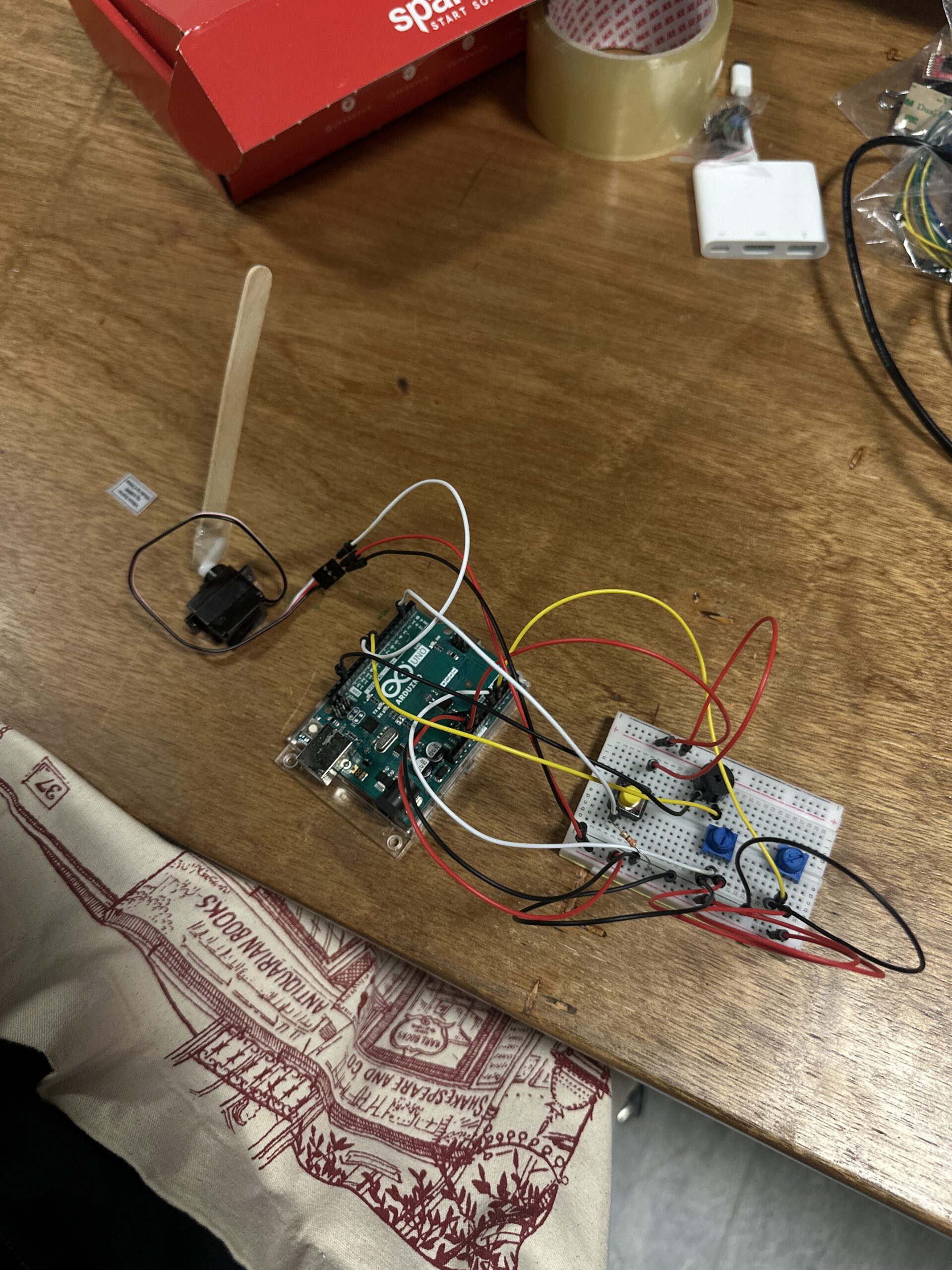
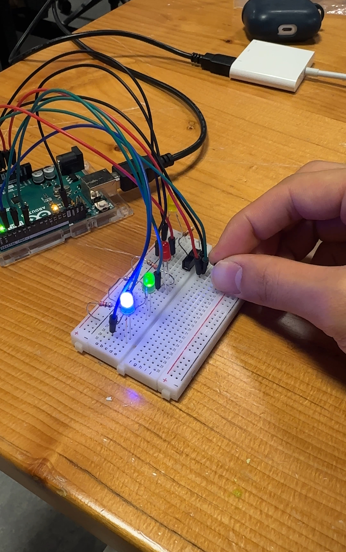
My Arduino code is fairly simple since I used some of the class templates. For the accelerometer, because we need to map the sensor value to the plane’s y position in p5, we use analogRead(A0) to read the sensor value from analog pin A0 and send it to p5 through the serial port. Likewise, we read the sensor value from the button using digitalRead(). For the LED lights, we read one character from p5: if it is 1, we turn on both LED pins; if it is 0, meaning the user is not collecting stars, we turn them off. I also set a delay of 100 to prevent sending sensor values to p5 too rapidly, which would make the plane shake due to the accelerometer’s sensitivity.

// pin to read button press 
const int buttonPin = 2;

// LED pints to light up when stars are collected
const int led1 = 8;
const int led2 = 9;

unsigned long ledOnTime = 0;  // record when the LED turns on 
const unsigned long ledDuration = 500;  // LEDs turn on after 500ms

void setup() {
  Serial.begin(9600);
  pinMode(buttonPin, INPUT); // set to input since we want to send sensor values 
  pinMode(led1, OUTPUT); 
  pinMode(led2, OUTPUT);
  digitalWrite(led1, LOW); // turn off first
  digitalWrite(led2, LOW);
}

void loop() {
  int x = analogRead(A0); // read accelerometer value (0 to 1023)
  int btn = digitalRead(buttonPin); // read the button state 
  Serial.print("ACC:"); 
  Serial.print(x); // print accelerometer value
  Serial.print(",BTN:");
  Serial.println(btn); // print the button state (1 if is's pressed)

  if (Serial.available()) {
    char c = Serial.read(); // gets one character from p5
    if (c == '1') { // if it is 1
      // turn on the LED pins
      digitalWrite(led1, HIGH);
      digitalWrite(led2, HIGH);
      // save the time so that LEDs can turn off automatically after 500 ms
      ledOnTime = millis();
    }
    if (c == '0') { // if it is 0
      // turn off the LEDs 
      digitalWrite(led1, LOW);
      digitalWrite(led2, LOW);
      // reset the timer to 0
      ledOnTime = 0;
    }
  }

  // if the LED has been lighting up for more than 500 ms
  if (ledOnTime > 0 && (millis() - ledOnTime) >= ledDuration) {
    // turn both off
    digitalWrite(led1, LOW);
    digitalWrite(led2, LOW);
    ledOnTime = 0;
  }

  // set delay to 100 so that plane on p5 won't be too sensitive 
  delay(100);
}

Full Arduino Code

Communication between P5 and Arduino:

Arduino and p5 communicate with each other in three ways. First, the accelerometer on the plane controller measures the tilting angle and sends sensor values to p5 so that the plane on the screen moves up and down accordingly. Second, there is a button on the plane that boosts the plane’s speed in p5 when pressed. When the button is pressed, we send its sensor value through the serial port, and p5 processes it. Lastly, there are two LED lights on the physical plane. Whenever the plane in p5 collects a star, p5 sends either a 1 or 0 to Arduino to turn the LEDs on or off. This represents communication from p5 to Arduino.
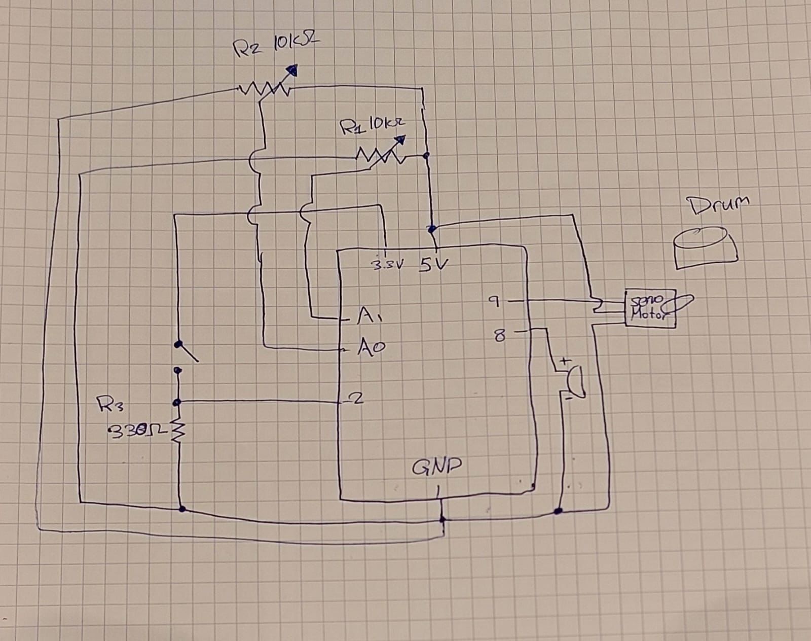
Schematic:

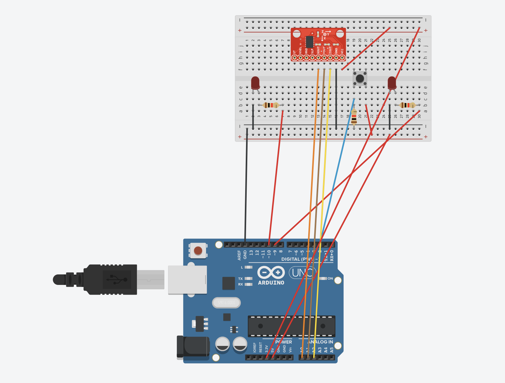
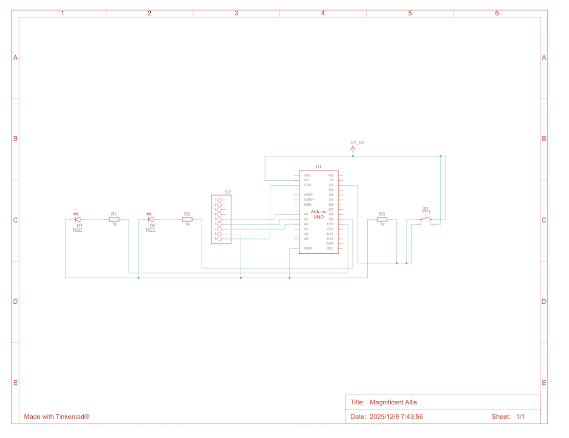
For some reason, the image is too blurry, so you can see the clear image of schematic through the link below:

Schematic (clear version)

User Testing & Experience:

Some people told me that the screen was a bit too laggy, so it was a little hard to play. Since this is a technical issue related to my laptop, I think I will need to use a better computer with a stronger CPU. I also received feedback at the IM show, and one professor mentioned that it would have been very nice if the airplane were shown from the user’s perspective. That way, the game would feel more interactive and immersive. So next time, I will improve the UI and make users feel like they are actual pilots.

These are the videos of users I filmed during IM Show.

User 1

User 2

User 3

What are some aspects that you are particularly proud of: 

I’m especially proud of the button on the physical airplane because it was very challenging to embed it securely. At first, I considered using a LEGO block to hold the button in place, but it was too unstable. Instead, I decided to make a hole in the plane and embed the button directly. To do this, I asked a professor from Creative Robotics to help me understand how to use different drills to create a precise, tiny hole for the button. I also used a glue gun to attach it firmly to the plane. As a result, the button became very stable.

Future Improvements:

For future improvements, I would like to add a vibration motor to the physical airplane so that users can feel feedback when the plane in p5, for example, gets bombed. Additionally, since there are currently many wires coming out of the airplane, I want to reduce them to make the controller easier to use. In terms of UI, I want to add a moving character on the plane so that users feel as if they are actually riding it. I believe these improvements would make the game more interactive and visually engaging.

References:

For resources, I watched this tutorial ( https://www.youtube.com/watch?v=zpV7ac3ecl4 ) to learn how to use the accelerometer, especially because I didn’t know how it worked. It helped me understand which pins to connect and that there are 3 vectors I can use to measure the tilting angle. I also used ChatGPT to adjust the position and size of each button and screen element using getScale and scaleSize, which are custom functions I designed. The getScale() function helped me pick the smaller ratio between (800, 600) and (curWidth, curHeight), and use it as a base scale factor, which we multiply by the size of each element inside scaleSize(). This effectively helped me adjust the position and size of each component both in fullscreen and non fullscreen modes.

Furthermore, I learned about localStorage, which is a browser API that allows user data to persist on their browser even after they close it. This helped me create a persistent leaderboard that can store as much user data as needed. Lastly, I asked ChatGPT to figure out why the LED lights were not lighting up properly, and it told me that I had not placed the wire in the correct position. I used the class templates, but ChatGPT helped me work through the additional details I needed to complete my interactive game.

Week 13: User testing

Link to Video

Are they able to figure it out? Where do they get confused and why? Do they understand the mapping between the controls and what happens in the experience?

I had two users test my final project, “Tokyo Flight,” and they were able to figure out how to play the game using the physical airplane controller I built. The instruction page was helpful overall, but they initially got confused because it first explained how to play the game within p5 only. This made it very confusing for them to understand how to use the physical airplane to control the plane on p5. The tester eventually understood the mapping between the controller and p5. However, the button on the physical airplane took them some time to understand how it works. Thus, I need to improve the instruction page to clearly explain how to play the game using the physical airplane.

What parts of the experience are working well? What areas could be improved?

The airplane on p5 successfully received sensor values from the accelerometer, so the main feature of the game was working perfectly. Specifically, the airplane on p5 moved vertically according to the tilt of the physical airplane. However, one of the LED pins was not working properly due to a loose wire connection. I had to fix it manually during the game to get the LED to light up. To rectify this issue, I am thinking of using a glue gun or tape to make the connection stronger so the wires do not come loose during the game. Furthermore, the testers told me that the entire experience was a bit too laggy, which made it difficult to play the game. To fix this, I moved all the files to VS Code and used Live Server, which resolved the lagging issue.

What parts of your project did you feel the need to explain? How could you make these areas more clear to someone that is experiencing your project for the first time?

I definitely need to improve the UI of the p5 interface, since some text are overlapping with each other, and the Airplane Collection page has poor UI design. Specifically, the point values are hidden behind each box, so users cannot easily understand how many points they need to get to unlock each skin. I also realized that I needed some kinds of background music to make the atmosphere better, based on the tester’s feedback. I added Ghibli music since the main theme is about this ghibli movie called Wind Rises. The tester also told me that the accelerometer is very sensitive and that depending on the delay, sensor values are sent to p5 too quickly. This causes the tilting movement of the physical airplane and the airplane movement on p5 to be sometimes mismatched. I will experiment more with the delay values on arduino to find the best delay value that avoids lag or mismatch between the real tilting movement and the airplane movement on p5.

Week 12: Tokyo Flight inspired by The Wind Rises (Final project concept)

Final Project Concept:

“Tokyo Flight” is an interactive flying game that is inspired by one of Ghibli movies called The Wind Rises. The player controls a cardboard airplane equipped with an accelerometer and a button, both of which are connected to Arduino. The way the game works is that the user is going to tilt the airplane and the airplane on p5 will follow the movement of the tilt. The goal of the game is to pass through as many floating rings as possible without touching them or going out of the canvas. If users press the button on the airplane, then the speed of the airplane on p5 will boost up to help reach difficult rings. If the player collides with a ring or flies out of the screen, the flight ends. 


Arduino Components:

    • Accelerometer (MPU6050) inside the airplane: It measures the tilt forward and backward. Possibly left or right tilt as well.
    • Push buttons: It triggers a temporary speed boost.
    • LED lights: Light up when the boost is active


What Arduino does:

    1. Read sensor values: 
      • It continuously read acceleration + gyroscope data from the MPU 6050
      • We smooth the data to remove the noise 
      • We convert the tilt into a single value (from -90 degrees to 90)
    2. Read button state: 
      • We check if the button is pressed or not
      • Sends a signal (0 or 1) 
    3. We send data to p5.js through webserial 
    4. Additional feature: 
      • We receive signals from p5 to blink LED when boost is available 
      • Vibrate the motor when the user crashes 


What p5.js game will do:

    1. Connect to arduino via webserial 
      • We parse incoming serial strings and extract tilt angle and button state
    2. Control the on-screen airplane
      • We map tilt to the airplane’s vertical position. 
      • We also map horizontal tilt to slight horizontal drift
      • If speed boost button is pressed, we increase forward movement temporarily 
    3. Generate game objects: 
      • Rings appear from the right and move left 
      • Rings vary in size and vertical position 
      • We generate a wind to affect the airplane’s movement 
    4. Collision detection: 
      • If the airplane touches ring boundary, it is game over 
      • If the airplane goes beyond the canvas, it is game over. 
    5. Scoring System 
      • +5 for passing through small rings
      • +2 for passing through big rings 
    6. Visual and Audio design: 
      • We will have a soft blue sky with clouds and a green glassfield at the bottom to represent Wind Rises.
      • We will also play Ghibli audio while the game is playing 
    7. Send feedback to Arduino
      • Arduino flashes LED lights when the airplane crashes
      • Arduino keeps lights on when the airplane is on boost mode 
      • Arduino vibrates when the airplane goes through the rings.


Week 11: Final Project Concept

Main Concept

The main concept for my final project is the “Lock In Buddy.” It basically never lets you stop studying. Your laptop acts as the monitor, and the system uses Arduino sensors and p5 to track your behavior while you are studying. If it detects your phone, it triggers a super loud alarm. If it senses that you’re leaving the table using a distance sensor, it activates the speaker and says, “Come back to the desk. You gotta lock in!” I also want to incorporate the Pomodoro technique, where you study for 25 minutes and take a 5-minute break. A student can press a physical button to start the timer, and press it again to stop it. At the end, the system will give you a score based on how distracted you were by environmental variables, like looking at people walking by, eating, or any other interruptions. Essentially, it becomes your study buddy until you graduate.


Lock In Buddy will have these features: 

    • Phone detection alarm 

It will detect when the user picks up a phone, uses, or brings their phone to a nearby desk. The monitor is always watching the user to make sure that they don’t use their phone. 

    • Leaving the desk detection 

The distance sensor detects when the user moves away from the study area. It plays a warning voice message saying “you gotta lock in buddy. Or you will become homeless”. 

    • Real time distraction detection 

The system detects whether you’re being distracted by environmental conditions. Those include looking at people passing by, eating, chair movement, or noise.

    • Pomodoro timer with physical buttons 

Users can press the button to start, pause and stop the Pomodoro session. Also, it will record how long you have been studying for, which is going to be recorded for the scoring system as well. 

    • Focus score generation 

P5 will calculate the number of distractions, phone usage count, time away from desk, noise levels, and the number of successful Pomodoro sessions.


How to integrate p5 and Arduino

Phone detection + alarm: 

    • p5.js + Webcam + ML5 COCO-SSD 

Or 

    • Arduino light sensor + phone jail box
    • Start playing the warning alarm saying “Lock in” in p5


Eating or talking: 

    • Sound sensor


Pomodoro Timer with physical buttons: 

    • Buttons with arduino


Leaving desk: 

    • Ultrasonic distance sensor 


Focus Score generation: 

    • Arduino continuously reads 
      • Light sensor → phone removed 
      • Ultrasonic sensor → left desk 
      • Sound sensor → eating/talking 
      • Button → start/stop Pomodoro
    • Send those data to p5 and calculate the score 

week 11: reading response

This reading gave me a new perspective on the intersection between disability and technology. I didn’t know that eyeglasses were initially made for the medical purposes only, so it was really interesting to learn how societal perceptions and stigma can change so dramatically over the course of time. I realized how powerful designers are in shaping these perceptions, as discussed in the reading. This is definitely something that engineers cannot achieve by themselves. As a prospective software engineer, I learned that my goal should not be just to make things useful, but to make them as simple and usable as possible for everyone in the world, like AirPods, irrespective of nationality and background. I’ve personally experienced how complexity can mess up the development process and even the essential purpose of a product.


For instance, I’m currently developing my mobile app that turns TikTok into studying. Initially, I wanted to integrate a social media feature where users can compete with each other in terms of how many questions they can answer in a row. But that feature turned out to be super complex, and spending too much time on implementing that single feature prevented the essential purpose of my app, which is to make studying addictive for students in the world. That is the reason why I decided to focus sorely on the scrolling system, since it is the simplest and most essential feature of TikTok that makes it so addictive. Through this reading, I was able to understand how important it is to make a product as simple and usable as possible for all the users in the world.

Week 11: Exercises – Shota and Isabella

EXERCISE 01: ARDUINO TO P5 COMMUNICATION

Concept:

For the first exercise we used a photoresistor as an analog sensor on Arduino to make our ellipse shape move on the horizontal axis in p5. For our code, we adjust it so that with every touch on the photoresistor, the ellipse would move on the canvas.

VIDEO:

video1

Code we’re proud of:

When it comes to the first exercise, the part we are most proud of is the block of code that controls the x-position of the ellipse using the light sensor value from the Arduino. We read the sensor value through the serial port that is connected to the Arduino and map it from 0 to the width of the canvas so that it never goes out of the dimension of the screen.

//read the data coming to the port until the newline character
   let data = port.readUntil("\n");
   //if there is a data
   if (data.length > 0) {
     //convert the clean data into integer
     rValue = int(trim(data));


     //store data of left and right into msg
     let msg = left + "," + right + "\n";
     //send the msg back to the Arduino
     port.write(msg);
   }


   text("rValue = " + rValue, 20, 50);
 }


 //move xpos depending on the sensor value (max = 640)
 let xpos = map(rValue, 550, 900, 0, width);
 fill(0, 0, 255);
 ellipse(xpos, height / 2, 100, 50);


EXERCISE 02: P5 TO ARDUINO COMMUNICATION
Make something that controls the LED brightness from p5

Concept:

For the second exercise we used the createSlide function to create a slider on the canvas of p5. This way, every time we moved the slider to the right, the brightness of the LED on the Arduino would increase, and every time the slider was moved to the left, the brightness would decrease.

VIDEO:

video2

Code we’re proud of:

For the second exercise, this block of code combines what we learned during the class about p5.js (createSlider) and Arduino. Since we remembered using a slider to control a value or game score, we decided to use it to control the brightness of the LED. We take the slider value, store it in a variable called brightness, and send it to the Arduino through the serial port, as shown in the block of the code below.

//read the slider value
 brightnessValue = brightnessSlider.value();


 //if the port is open
 if (port.opened()) {
   //store the brightness value from the slider
   let msg = brightnessValue + "\n";
   //send it to Arduino
   port.write(msg);
 }


EXERCISE 03: BI-DIRECTIONAL COMMUNICATION

Concept:

For the third exercise, we made use of a potentiometer ( analog sensor ) on Arduino and a LED light, connecting it on the corresponding pins and then connecting Arduino UNO with P5. After adding the necessary codes on P5, we adjusted our “ball” so that every time it bounced against the floor, the LED would light up, and once it stopped bouncing the LED turned off. With the potentiometer, we were able to control the “wind”, causing the ball to be pushed from side to side, depending on the direction in which we turned the potentiometer.

VIDEO:

video3

Code we’re proud of:

For the third exercise, we’re proud of the block of code below. It basically captures the main objective of this exercise. When the ball reaches the ground and the LED state is 0, meaning the LED is currently off, we turn it on by sending a 1 to the Arduino through the serial port. It is simple but we needed to understand the basics of what is going on in the vectors. 

//if the ball reached the floor and the led is currently off
 if (isBounced && ledStatus === 0) {
   //turn the LED on
   port.write("1");
   //set the state to 1
   ledStatus = 1;
 }
 else if (!isBounced && ledStatus === 1) {
   //turn the led off
   port.write("0");
   ledState = 0;
 }


Challenges and Further Improvements:

Fortunately, we were able to complete all the assignments successfully, and managed to achieve all the necessary responses of P5 and Arduino. For each exercise, we started by planning out which tools we would use, how to arrange them on our breadboard, and once this was done, our greatest challenges consisted of arranging and adding the codes required to make each response function. On the third assignment we especially struggled writing the codes required to make the potentiometer affect the “wind” and consequently the direction in which the ball was pushed. For future improvements, we would like to grasp a better understanding of the exchanges between P5 and Arduino in order to make more complex and interactive responses that can also satisfy the assignment’s requirements.


Github Link:

exercise1 Arduino

exercise1 p5

exercise2 arduino

exercise2 p5

exercise3 arduino

exercise3 p5

Reference:

We used ChatGPT to help us understand the bouncing ball template code since we hadn’t yet learned about the vector library in class. After understanding the foundation of it, we were able to integrate the isBounced logic into the template code to detect whether the ball was bouncing or not. Thus, we’re glad we were able to learn a lot about vectors library. We also used ChatGPT to learn about DOM library methods such as .position() and .style(). Although we had covered the basics of createSlider, we didn’t delve deeper into it during the class, so we needed to learn how to adjust its position and CSS styling of the ball.

Week 10: Reading Response

After reading this article, I was reminded of Mark Zuckerberg’s quote where he said that the next biggest innovation is going to be VR. The author emphasized that the incorporation of more senses into these technological devices allows people to really interact with them in a much deeper sense, whereas smartphones are just composed of screens and we just scroll on the glass, not getting any feedback. At first, I thought we still get tactile feedback from the screen. For instance, when we are playing games and get attacked by someone, we feel the vibration. But that does not foster any intimate interaction between users and the device itself. What makes an experience more unique and immersive is stimulating as many human senses as possible, something that I learned in the class I took when I was a sophomore, called Immersive Experiences. I think for my final project, I want to do something that can impact people’s thoughts and make them reflect on their past experiences through immersive experiences. Through these two articles, I learned that we are shifting to a world where the distance between technology and humans is getting much closer. I am somewhat worried about it because there are already cases where people get confused about their identities since they spend most of their time in a digital world. I think it is best to create a boundary between us and technology to remain humanities in this world.

Week 10: Group Project “NYUAD DJ Kit”

Main Concept:

The main concept for our group project is a DJ, since we wanted to experience what it feels like to be one. A DJ needs to handle many sounds and instruments using their unique artistic skills to create music that makes people happy and excited. Thus, we crafted this device called “NYUAD DJ Kit.” By using it, you can choose different kinds of songs with various speeds and a base sound produced by a wooden stick. This is a unique way to compose new kinds of songs as a DJ. 

Demonstration Video


Schematic:


Code we’re particularly proud of:

The parts of the code we’re most proud of are the one shown below. The if else statement allows us to move to the next song and play it. When the button is pressed, meaning the pin is low, we set buttonPressed to true and noteIndex to 0 so that the song plays from the beginning. We also used the modulo operator to ensure that we always go back to the first song after the last one. The else if statement resets the buttonPressed state to false, so that the next time we press the button, it plays the next song. 

//handle music switching using modulo
if (digitalRead(BUTTON_PIN) == LOW && !buttonPressed) {
    buttonPressed = true;
    //move to the next song
    currentSong = (currentSong + 1) % 3; 
    //set note to 0 so that a song plays from the beginning
    noteIndex = 0; 
    isPlaying = false;
    noTone(BUZZER_PIN);
    delay(250); //delay for 250 milliseconds
  } else if (digitalRead(BUTTON_PIN) == HIGH) {
    //set buttonPressed to false to play next song 
    buttonPressed = false;
  }


The second snippet of code allows the servo to move every servoDelay milliseconds, controlling its speed and angle. We applied the concept we learned in class called “non-blocking” to ensure that this operation does not affect the rest of the program. Inside the if statement, we use the write() function from the Servo library to change the servo’s angle each time it runs. This way, the servo continues changing its angle until it reaches either 180° or 0°, incrementing by a step each time servoDelay milliseconds have passed. We’re happy that we were able to apply multiple concepts we learned in class, such as non-blocking and modulo, to our DJ project. As references, we used the example file ToneMelody from the Digital section and the Knob example from the Servo library. We also used ChatGPT to help us figure out how to apply the non-blocking concept so that the melody can move to the next one without affecting the rest of the program, which allows the servo to continue moving smoothly.

//Use non-blocking to not affect the rest of the program
if (currentTime - lastServoUpdate >= servoDelay) { //if servoDelay mills has passed
    lastServoUpdate = currentTime;
    //Change the angle of the servo by servoPos 
    myservo.write(servoPos);
    servoPos += servoStep;
    //Start decrementing if servo reaches 0 or 180 degrees
    if (servoPos >= 180 || servoPos <= 0) servoStep = -servoStep;
  }


Link to GitHub: https://github.com/KimShota/Intro-to-IM/blob/13b494508781fc36c9b95d3b46e5145d18c06808/nyuad_dj.ino

Reflections & Future Improvements:

In terms of reflections, we struggled a lot to make the base work because we needed to attach the wooden stick to the servo and it was not stable at all at first. The way we attached it was by using tape, which was the primary cause of why it was unstable. As a result, every time we ran the servo fast, the stick fell off or the servo stopped working for some reason. We eventually managed to make the stick and servo stable by placing some weight on top of the setup so that no matter how fast the servo moved, the stick remained stable. 

As for future improvements, we want to enhance the quality of the base because right now we’re just using a wooden stick, and it doesn’t produce a loud enough sound for a party situation. Furthermore, as the stick swings faster, its swing range becomes smaller, so we need to move the bottle manually to allow the stick to reach it. We believe this happens because the servoDelay becomes too small, reaching about 1 ms, so the servo can’t physically keep up. Therefore, next time we should use constrain() on the mapped value to prevent electrical noise from going out of range. This way, we can allow the servo to catch up with the speed that we want.

Week 9: Reading Response

Thinking about the artwork “Remote Hugs”, I believe current physical computing devices are incapable of understanding and replicating human emotions due to their complexity. Emotions are constructed through a series of events that occur throughout one’s life, and we need to comprehend each event to truly understand and simulate one’s emotions. Since Remote Hug does not have the capability to analyze people comprehensively, I think it cannot replicate human warmth. Even the author mentioned that they were not able to understand the motivation behind it. Thus, I believe we need to integrate deep learning or machine learning mechanisms into such affective computing devices to better understand one’s emotional states.

In terms of the second reading, I disagree with the author in the sense that we should not completely let the audience interpret the meaning and purpose of an artwork on their own. I used to be a big fan of this idea, but that idea changed after I went to teamLab. When I visited teamLab, I experienced all the immersive artworks there but I was confused about what they were trying to convey and what kinds of experiences they wanted me to have. At the end of the day, I was completely lost and feeling dizzy heading back to campus. I think the essence of an artwork is to guide the audience through the experience, allowing them to connect it with their own personal thoughts and emotions. It goes back to the discussion we had about how we can incorporate randomness into artwork. As an artist, I think it is important to have a clear motivation and purpose behind the artwork and to guide the audience in how to interpret it.

Week 9: Analog and Digital Sensors

Main Concept:

I was always curious about using a temperature sensor because I could never imagine how such a tiny device can detect human temperature and convert it into volts. Therefore, I used this homework to experiment with the temperature sensor. I also decided to use the slider switch because I love the feeling of opening and closing it. I learned how to use the temperature sensor through an online tutorial (tutorial) since we have not yet covered it in class. It works quite simply. We supply electricity through the +VS pin to measure temperature internally, and the measured analog voltage is then sent back to the Arduino through the GND pin.


Figure 1 : temperature sensor + slide switch


Schematic

Full Video of Demonstration


Code I’m proud of:

This is the part of the code that I’m most proud of. First, I read the sensor value from pin A0 and convert it into millivolts since the temperature sensor calculates the corresponding voltage in millivolts. Then, I crafted this formula based on what I learned from the tutorial: each degree Celsius corresponds to 10 millivolts. Because the output voltage increases by 10 millivolts per degree Celsius, starting from 500 millivolts at 0°C, I subtracted 500 from the measured millivolts and divided the result by 10 to map the temperature to its corresponding voltage value. Converting Celsius to Fahrenheit was quite easy since I had already learned that in chemistry class.

//read the volatge from analogPin A0
  sensorValue = analogRead(A0);
  //convert digital numbers (0 to 1023) into voltage values 
  volts = sensorValue * maxVoltage / 1023.0;
  //convert volts into millivolts 
  millivolts = 1000 * volts;
  //convert into temperature in celsius
  celsius = (millivolts - 500)/10;
  //convert into temperature in fahrenheit 
  fahrenheit = (celsius * 9/5) + 32;


Reflections & Future Improvements:

Overall, I loved learning how to use the temperature sensor since I have always been fascinated by how such a tiny component can capture environmental variables. I was especially curious about why it has three pins, and I was able to understand the internal mechanism where we supply electricity to measure temperature, convert it into analog voltage, and send that voltage back to the Arduino. It was a bit challenging to find the right thresholds for each LED light to turn on and off smoothly. Sometimes I set the threshold of the last LED too high, so it never turned on. However, I was able to adjust them correctly through multiple experiments. For future improvements, I would like to combine the slider switch and temperature sensor so that they work together to control shared LED lights seamlessly. I tried doing this, but I had so many wires and LEDs that I struggled to find a proper way to connect them. Next time, I will spend more time figuring this out.