Concept
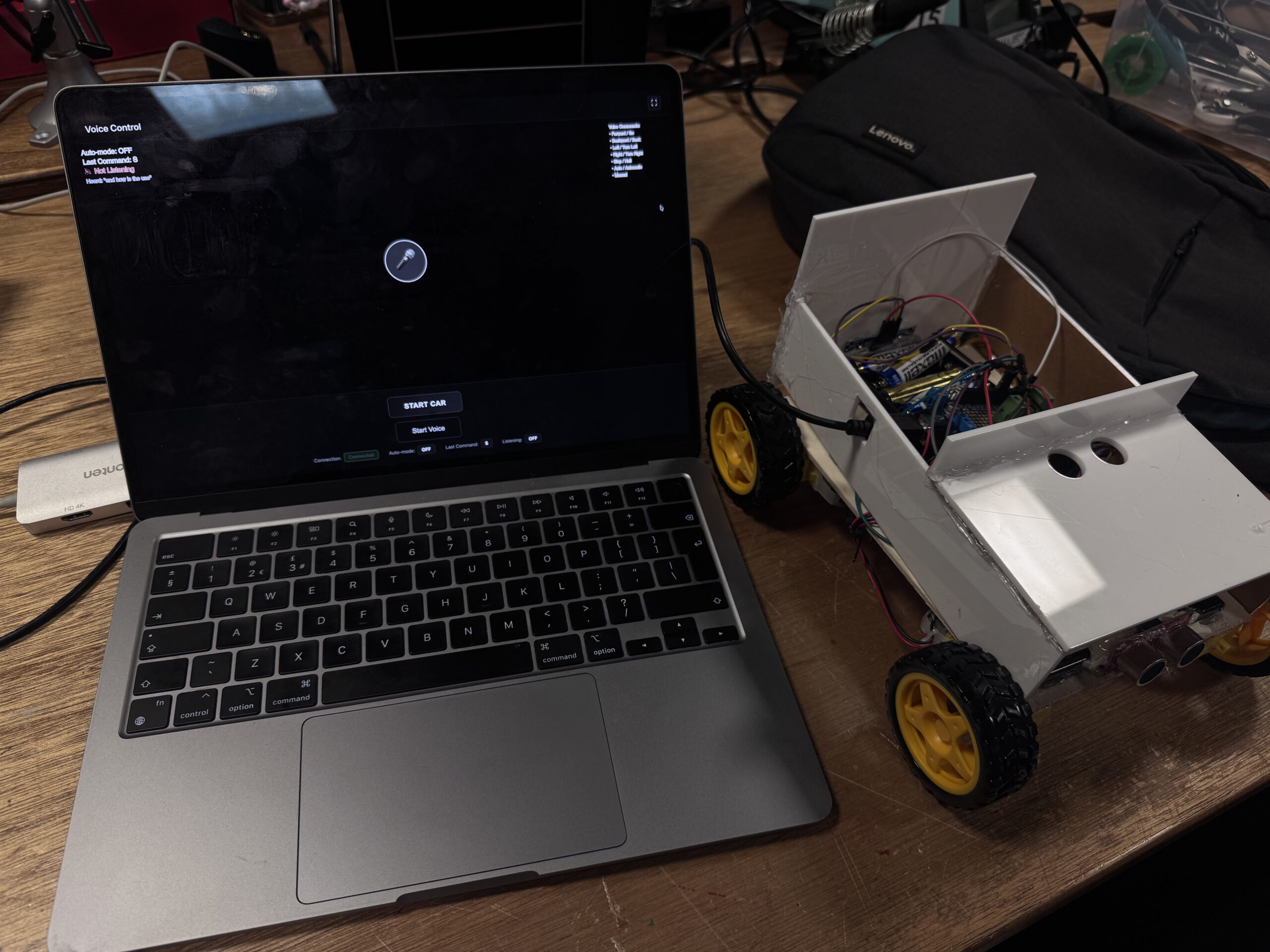
This project is a small car that connects to my laptop with a USB cable. Instead of using buttons, I control it with my voice. I say simple words like “forward,” “left,” “right,” “back,” or “stop,” and the car moves instantly. There is also an auto mode that lets the car drive itself while the screen shows what it’s doing.
My goal was to make something fun, hands-free, and beginner-friendly. Some videos of the project interaction can be found below
Here are some videos from the IM showcase:
How It Works
My laptop runs the p5.js and the Web Speech API. When I speak, the browser turns my speech into text, then the code matches the text to a command. It sends a single letter over the Web Serial API to an Arduino.
The Arduino reads that letter and moves the motors to go forward, back, turn, or stop.
A small “health check” in the JavaScript restarts the microphone if it stops listening. This makes the whole loop smooth and fast:
I talk → the browser listens → Arduino moves the car.
Interaction Design
The webpage shows everything clearly: whether the car is connected, if the mic is listening, the last command heard, and if you are in auto or manual mode.
A pulsing microphone icon tells you when to speak. Quick onboarding text teaches the basic words. The screen also shows what the system heard, so you know why the car reacted in a certain way.
Arduino Code Description
The Arduino code controls all the movement and safety features of the car. It uses the Adafruit Motor Shield to run four DC motors and two ultrasonic sensors to check the front and back distances. The laptop sends one-letter commands over serial—f, b, l, r, and s—and the Arduino reacts right away.
When a command arrives, the Arduino checks the sensors first. If the car is too close to something in the front and you say forward, the car protects itself by going backward instead. The same logic works for the back sensor. This gives the car a simple but smart safety layer.
Two LEDs show safety states:
-
Green → safe
-
Red → danger or warning
The code also includes turning functions that rotate the car in place for about 1 second to make a clean left or right turn. Everything is written in a clear, modular way so you can change speeds, turning time, and safety distances easily.
Below is the full Arduino sketch, which includes motor control, safety checks, distance reading, and serial command handling.
Arduino code : Github
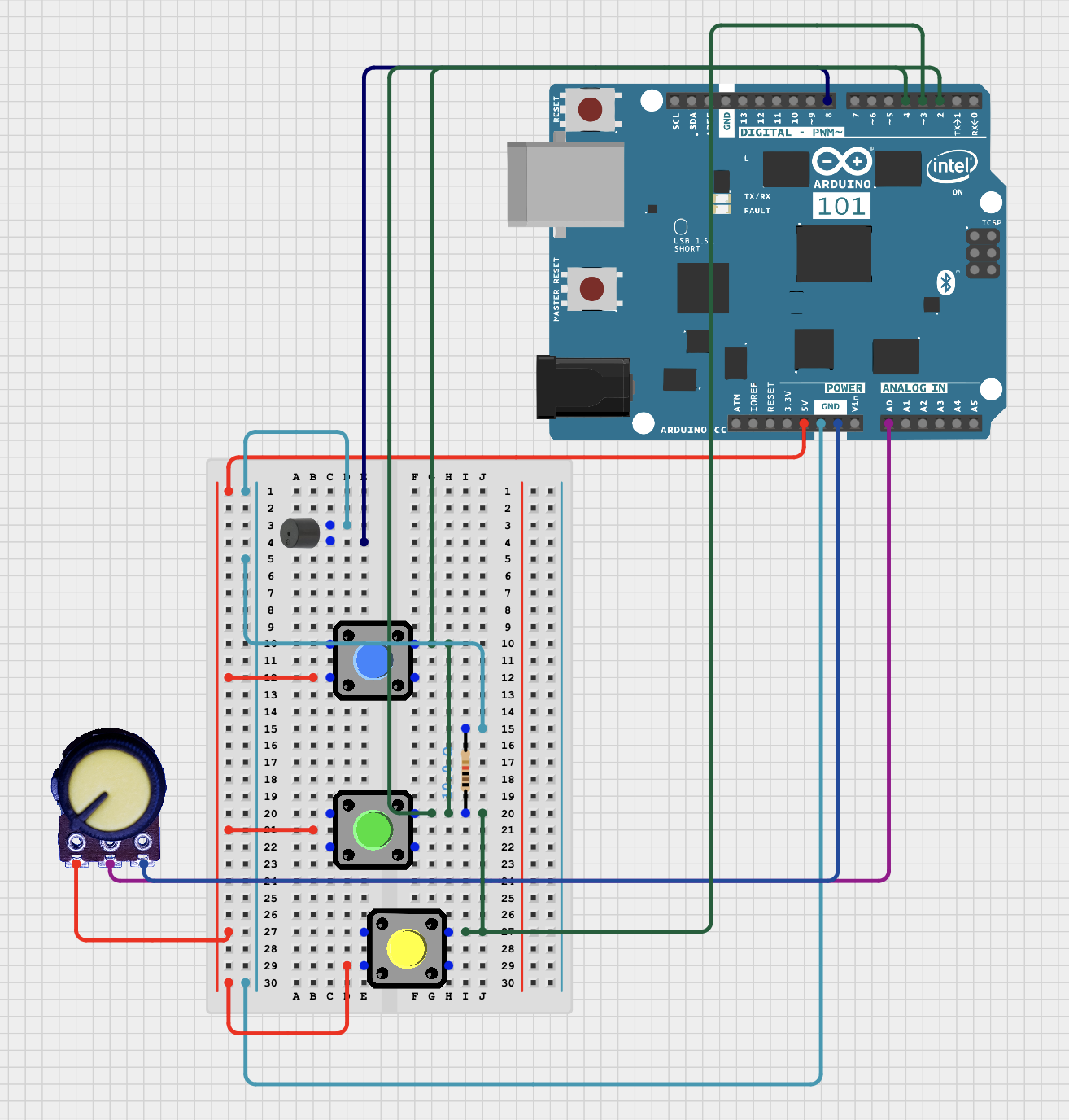
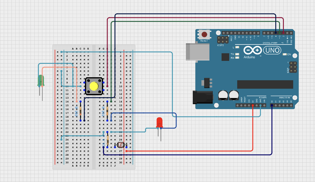
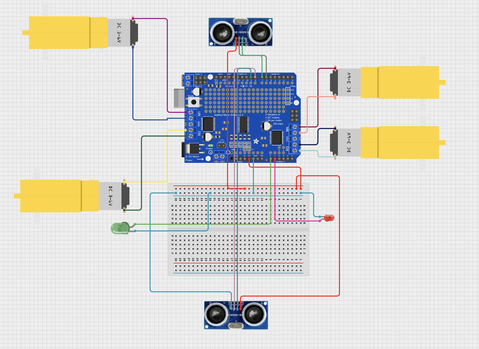
Circuit Schematic
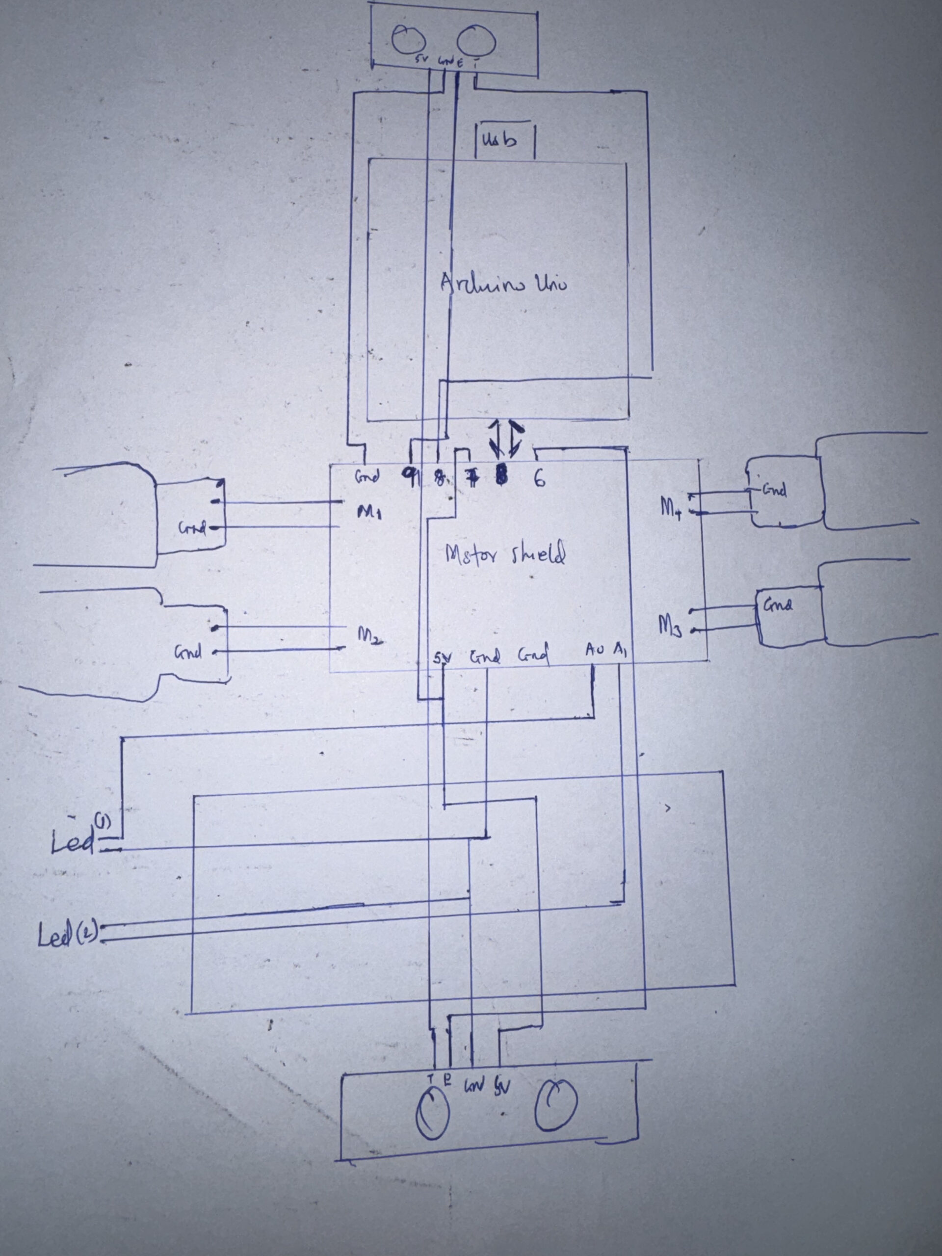
Schematics:
p5.js Code Description
The p5.js code is the control center of the whole project. It listens to your voice, figures out what you meant, and sends a one-letter command to the Arduino. It uses the Web Speech API to hear your words and a fuzzy-matching system so it can understand similar phrases like “go,” “ahead,” or “move forward.” Even small mistakes or accents are handled using a simple distance-matching algorithm.
The sketch draws the full interface: the microphone icon, the last command, auto-mode status, and a short list of voice commands. It also shows what the system heard in real time. If needed, you can use the arrow keys as backup control. The canvas resizes automatically, and there’s a fullscreen button for demos.
code : p5 – code
p5 project view : p5
Communication Between Arduino and p5.js
The connection between p5.js and the Arduino happens through the Web Serial API in the browser. When you press start button, the browser asks you to choose the Arduino’s USB port. After you allow it, p5.js opens the port at 9600 baud.
Whenever the voice system recognizes a command, p5.js sends a single letter to the Arduino:
-
f→ forward/go -
b→ backward -
l→ left -
r→ right -
s→ stop -
a→ auto mode
The Arduino listens on its serial port and reacts immediately to whichever letter arrives. p5.js also sends an s (stop) right after connecting to make sure the car doesn’t move unexpectedly.
This simple one-letter system makes communication fast, reliable, and easy to debug.
What I’m Proud Of
I like the voice system is, at first I was having a lagging in the voice control system , and also getting wrong inputs , so I saw this python system(Fuzzy string matching – Levenshtein distance)., which simplified everything for me. Also the auto-restart loop keeps the mic alive even during long testing sessions. And the UI makes the whole system feel clear and great. These little details make the whole experience smoother.
Future Improvements
Here are some things I want to add:
-
A wake word, so the mic listens only after a trigger phrase
-
Smoother motor speed and softer turns
-
Sensors for obstacle avoidance in auto mode
-
A stronger chassis with cleaner wiring and a power switch
-
Logging data to help tune performance over time
REFERENCES: This project used AI tools mainly to support coding and debugging . AI was used to help clarify technical concepts. It assisted in explaining algorithms such as fuzzy matching and Levenshtein distance, and in organizing the projects. The creative decisions, programming logic, user testing, and system design were all done by me, with AI acting only as a supportive tool for communication and explanation.
sources: Fuzzy-source