1. Concept
The Room Status Device is a physical indicator system designed to display whether a room is Available or Busy.
It uses:
- A slide switch to select the room status
- A 16×2 LCD to display the message
- Optional computer UI integration (p5.js) for serial communication
The goal was to create a simple, intuitive way to communicate room availability without relying on software or mobile apps.
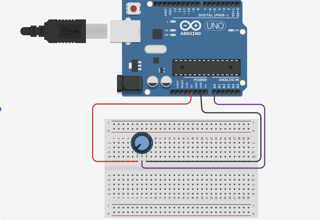
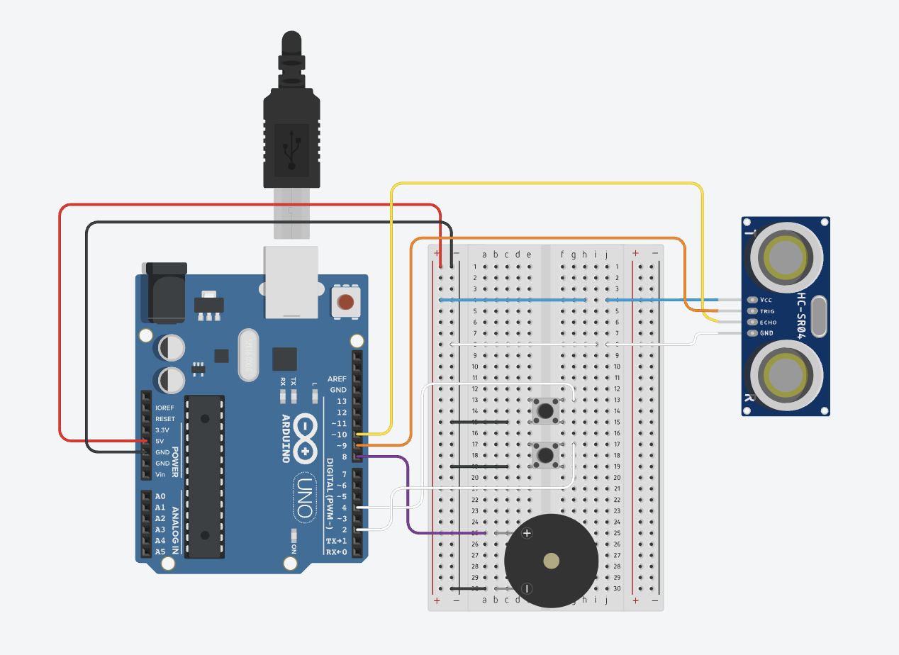
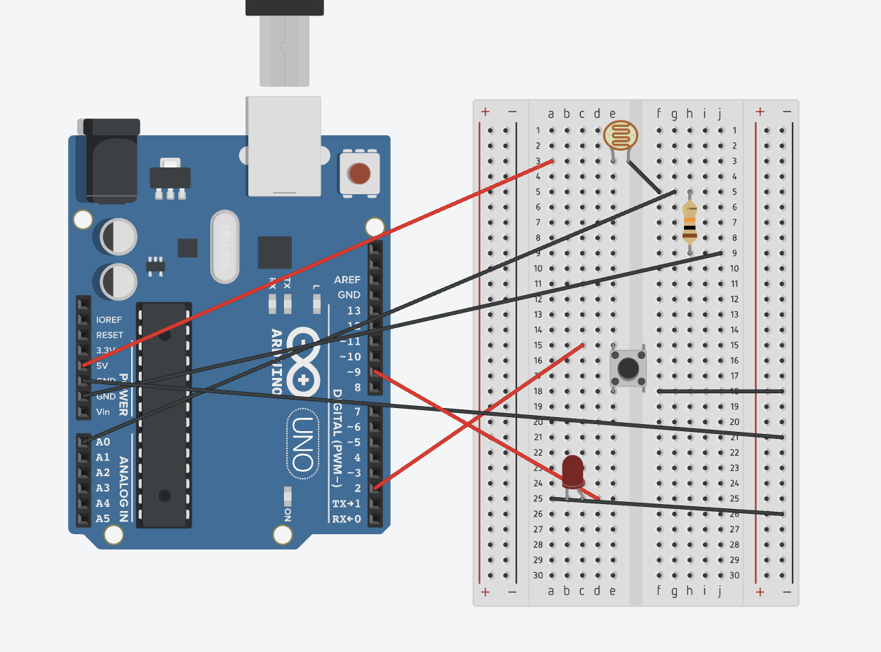
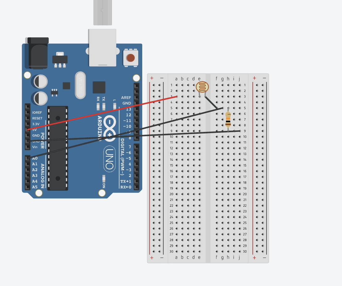
2. Images of the Project
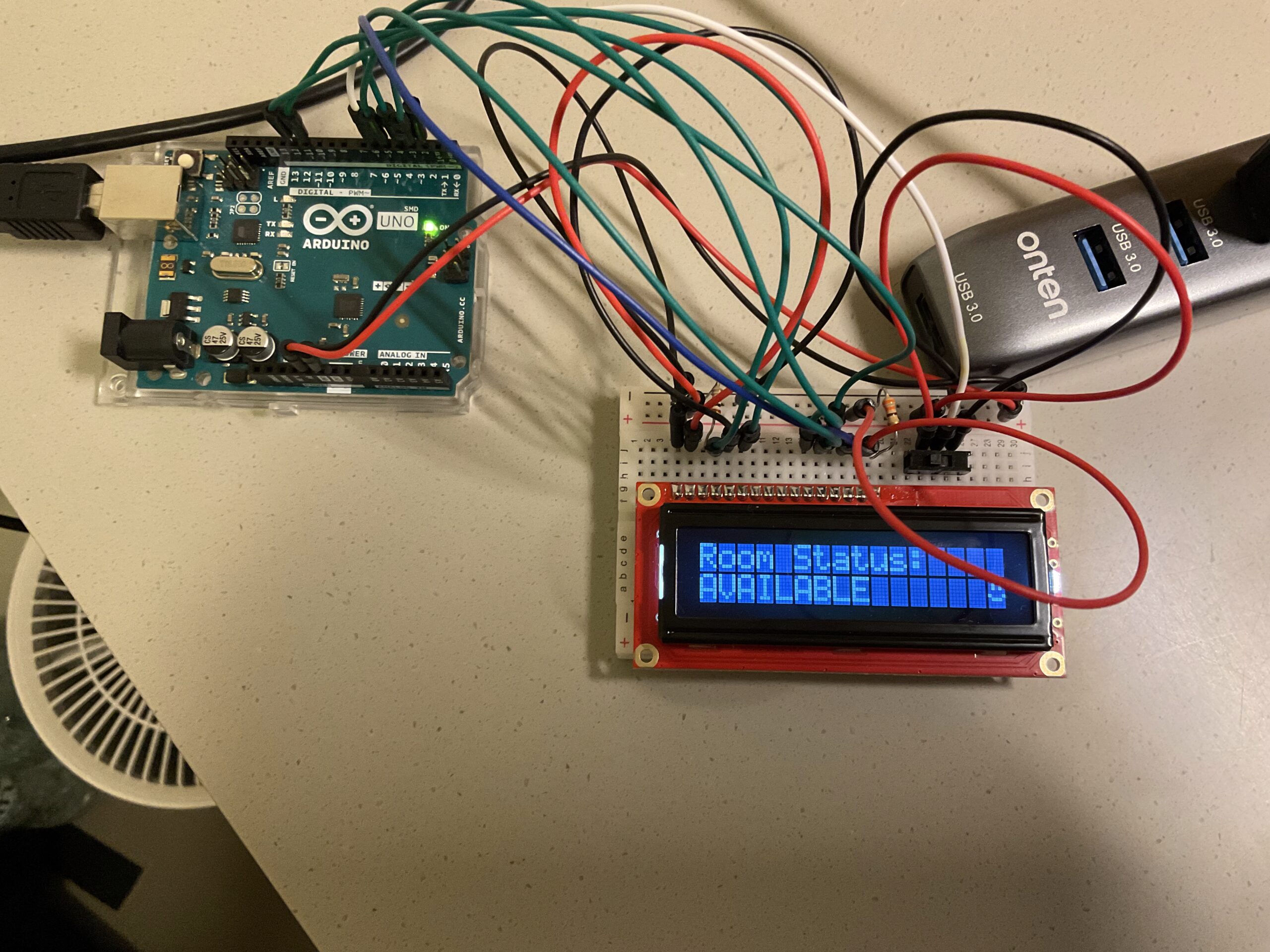
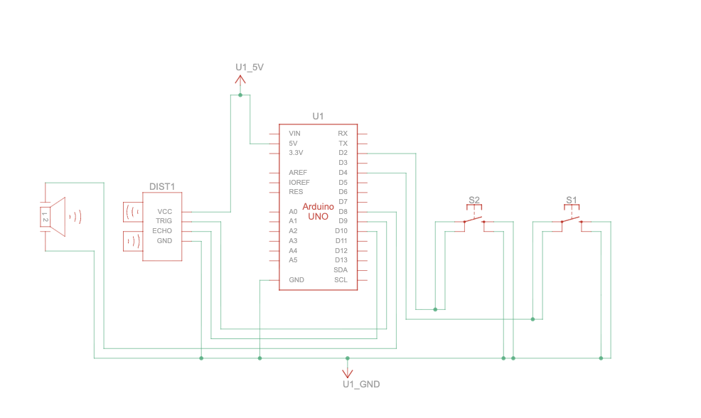
3. Schematic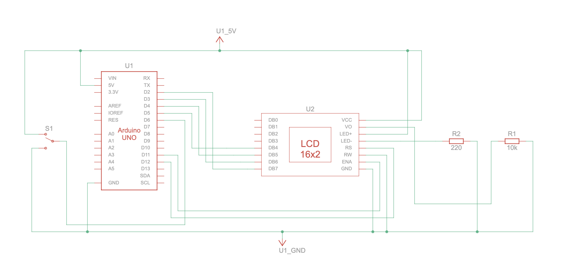
4. User Testing Videos
5. How the Implementation Works
Interaction Design
The user simply toggles a slide switch:
- Up → AVAILABLE
- Down → BUSY
The device updates the LCD instantly.
When connected to the p5.js UI, the device also sends status updates via serial for digital mirroring.
6. Arduino Code + Snippets
#include <Arduino.h>
#include <LiquidCrystal.h>
#include "DisplayManager.h"
#include "Emoji.h"
#include "Wireless.h"

const uint8_t SWITCH_PIN = 6;
bool lastSwitchState = HIGH;  // because of INPUT_PULLUP

DisplayManager display(12, 11, 5, 4, 3, 2);
WirelessHandler wireless(display);

void onSwitchStatusChangedToAvailable() {
  wireless.handleCommand("AVAILABLE");
}

void onSwitchStatusChangedToBusy() {
  wireless.handleCommand("BUSY");
}

void setup() {
  display.begin();
  wireless.begin();

  pinMode(SWITCH_PIN, INPUT_PULLUP);
  lastSwitchState = digitalRead(SWITCH_PIN);

  // Apply initial switch state
  if (lastSwitchState == HIGH) {
    onSwitchStatusChangedToAvailable();
  } else {
    onSwitchStatusChangedToBusy();
  }
}

void loop() {
  wireless.handleWireless();

  // Check switch state
  bool reading = digitalRead(SWITCH_PIN);
  if (reading != lastSwitchState) {
    lastSwitchState = reading;

    if (reading == HIGH) {
      // Switch position mapped to AVAILABLE
      onSwitchStatusChangedToAvailable();
    } else {
      // Switch position mapped to BUSY
      onSwitchStatusChangedToBusy();
    }
  }

  display.update();
}
7. p5.js Code + Snippets + Embedded Sketch
Full code: https://github.com/Building-Ling/Room_Status_Device
8. Communication Between Arduino and p5.js
Summarize the protocol:
- Arduino prints:
"AVAILABLE"or"BUSY" - p5.js listens via Web Serial
- Pressing F triggers fullscreen
9. Aspects I am Proud Of
- Clean, minimal hardware design
- Professional file structure
- Tidy p5.js UI
10. AI Tool Referencing
Chatgpt
Cursor
11. Challenges + How You Overcame Them
Version control: Git
12. Future Improvements
Improve UI