Concept
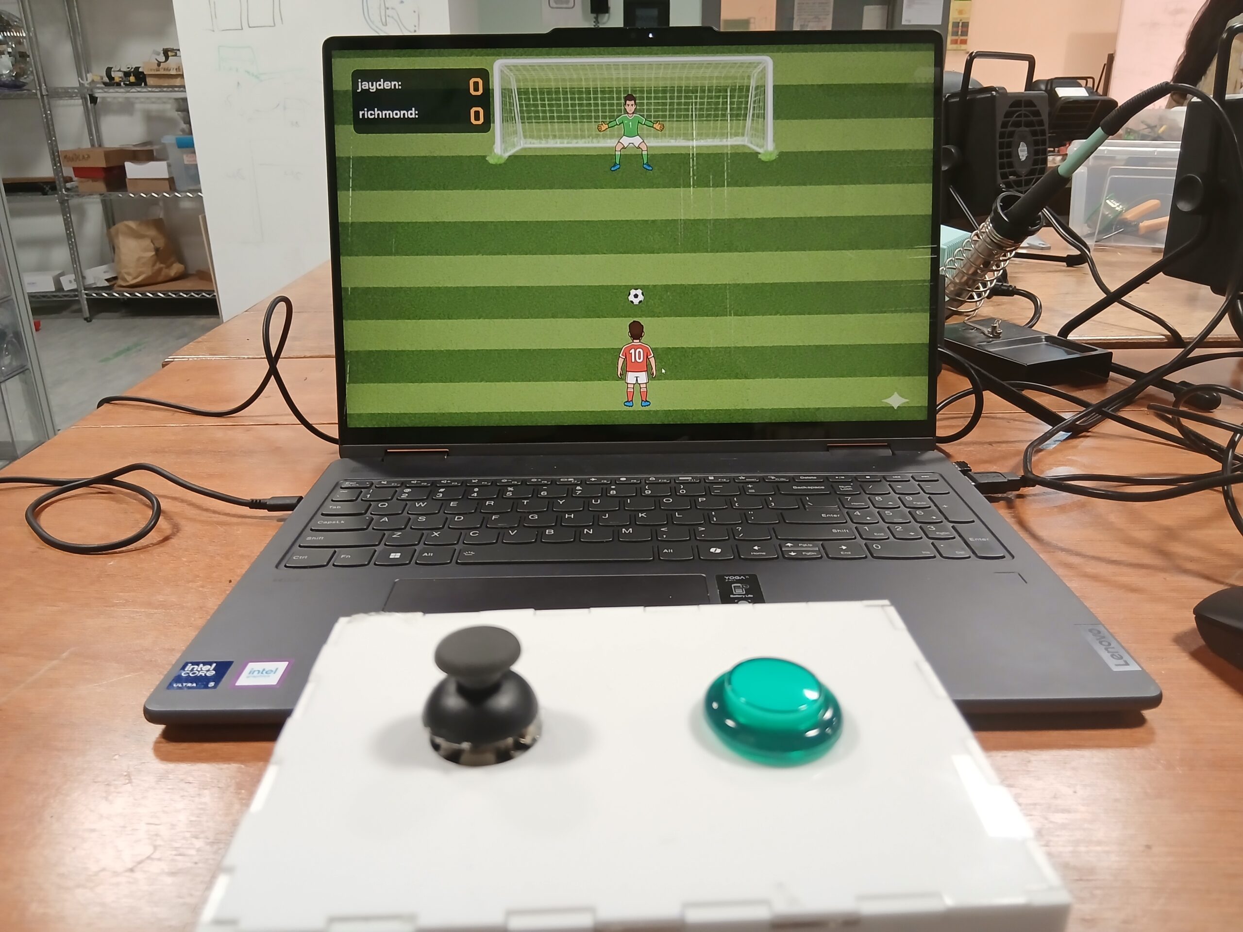
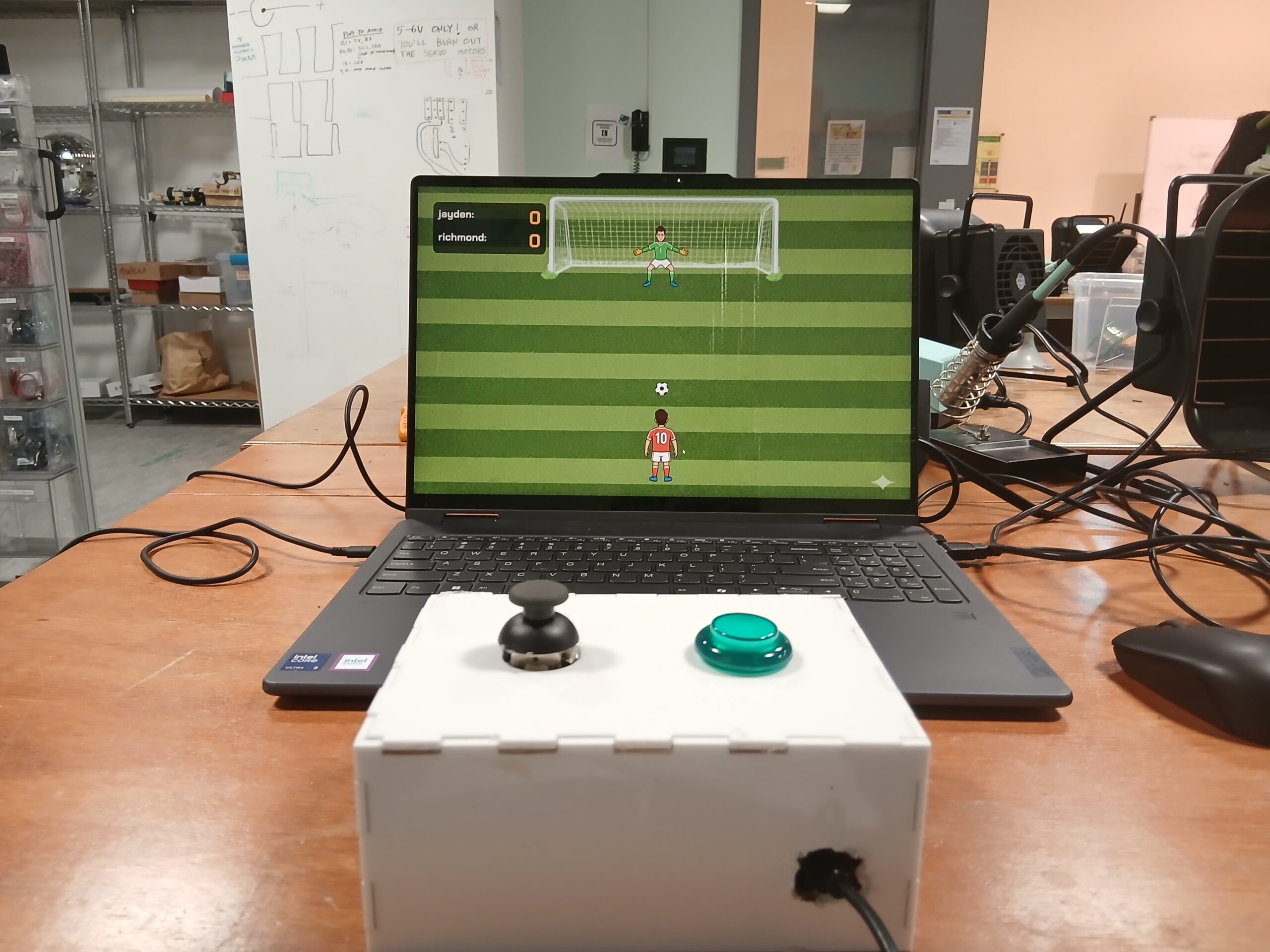
For my final project in Intro to IM, I created KICK ‘N’ SAVE, an interactive penalty-kick game that combines Arduino hardware, a joystick + arcade button, p5.js animation, and machine-learning hand-tracking using ML5’s Handpose model.
The idea was to create a soccer experience where the player controls the shooter with a physical joystick, while the goalkeeper is controlled by hand gestures picked up by a webcam. This combination of digital and physical interaction makes the gameplay energetic, intuitive, and fun for spectators.
The goal was to build something that feels like an arcade mini-game, is simple to understand immediately, and still feels alive because of the hand-controlled goalkeeper.
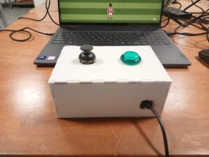
Images of the Project
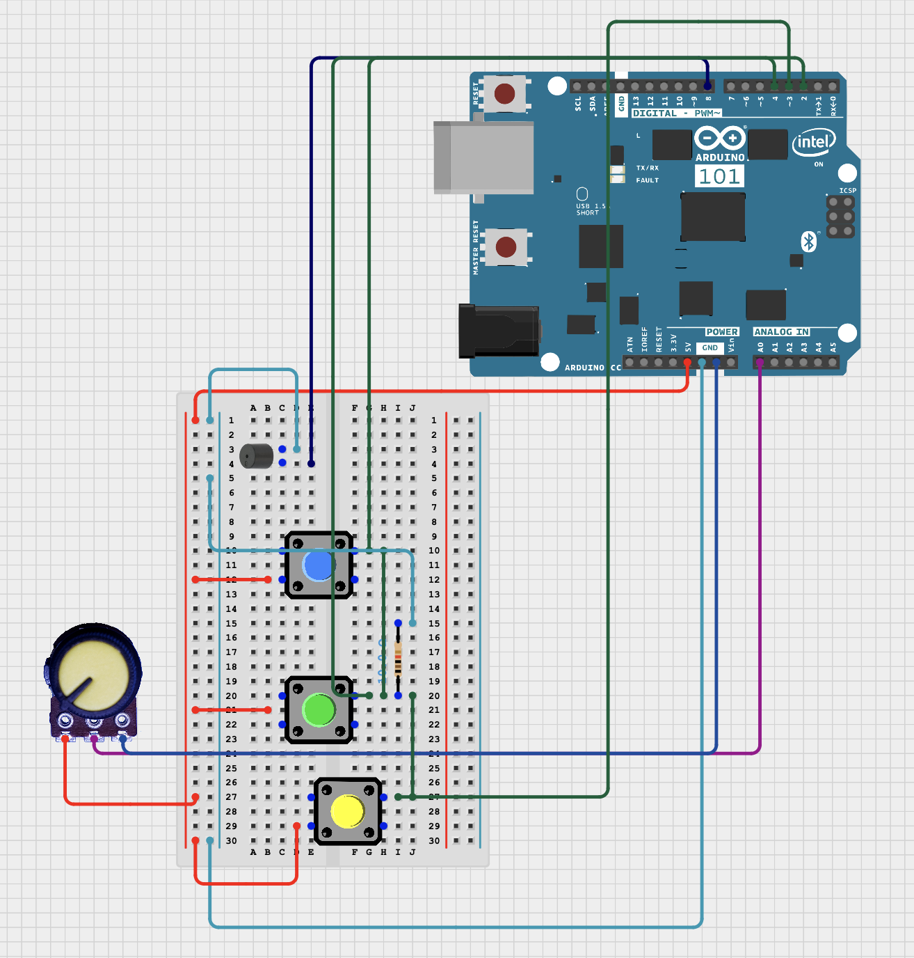
Schematic
User Testing Videos
How the Implementation Works
Interaction Design:
KICK ‘N’ SAVE involves two simultaneous interactions:
-
Shooter (player 1):
Uses a physical joystick-
Tilt ← → to select shot direction
-
Press the push button to shoot
-
LED flashes green if a goal is scored
-
-
Goalkeeper (player 2):
Controlled by hand gestures using a webcam-
Move hand to left/center/right
-
ML5 Handpose tracks the index fingertip
-
Keeper smoothly lerps toward the detected zone
-
Attempts to block the shot
-
The design intentionally creates a duel between physical and digital control.
Arduino Code:
The Arduino handles:
-
Joystick left/middle/right detection
-
Button press detection for shooting
-
LED flashing animation when p5.js sends ‘G.’
-
Serial communication to send ‘L’, ‘M’, ‘R’, and ‘S’ to p5.js
Code Snippet
// PIN DEFINITIONS

const int xPin = A0;        // Joystick XOUT
const int buttonPin = 2;    // Joystick Button (SEL)

const int GREEN_LED_PIN = 10; // Green LED (NOW: Arcade Button Light)

// JOYSTICK THRESHOLDS

const int thresholdLow = 400;
const int thresholdHigh = 600;

// State variables
String lastDirection = "M";  // Start in middle
int lastButtonState = HIGH;

// LED flash duration (1 second flash)
const int LED_FLASH_TIME = 1000;

void setup() {
  Serial.begin(9600);

  pinMode(buttonPin, INPUT_PULLUP);

  pinMode(GREEN_LED_PIN, OUTPUT);

  digitalWrite(GREEN_LED_PIN, LOW);
}

void loop() {

  // A. HANDLE LED COMMANDS FROM p5.js
  if (Serial.available() > 0) {
    char c = Serial.read();

    if (c == 'G') {
      digitalWrite(GREEN_LED_PIN, HIGH);
      delay(LED_FLASH_TIME);
      digitalWrite(GREEN_LED_PIN, LOW);
    }
    else if (c == 'R') {
      // Do nothing
    }
  }

  // B. READ JOYSTICK X-AXIS

  int xVal = analogRead(xPin);
  String currentDirection;

  if (xVal < thresholdLow) currentDirection = "L";
  else if (xVal > thresholdHigh) currentDirection = "R";
  else currentDirection = "M";

  if (currentDirection != lastDirection) {
    Serial.println(currentDirection);
    lastDirection = currentDirection;
  }

  // C. READ JOYSTICK BUTTON (SHOT)
  int buttonState = digitalRead(buttonPin);

  if (buttonState == LOW && lastButtonState == HIGH) {
    Serial.println("S");
  }

  lastButtonState = buttonState;

  delay(50);
}
Here is the link to the full code on GitHub: Github
p5.js Code:
The p5.js sketch handles:
-
Rendering the game visuals
-
Animating the ball based on the joystick-chosen direction
-
Keeper movement driven by ML5
-
Collision detection
-
Sending ‘G’ or ‘R’ back to Arduino
Embedded sketch
Parts of the Project That I’m Proud of
One of the things I’m most proud of in this project is how naturally the hybrid interaction system came together. The combination of a physical joystick for the shooter and ML5 hand tracking for the goalkeeper created a dynamic, two-sided experience that feels genuinely interactive and different from typical p5.js games. I’m also especially proud of the smooth goalkeeper movement—using lerp() to reduce jitter made the keeper feel responsive yet realistic, which dramatically improved gameplay. I’m also pleased with the UI design, especially the cartoon-style intro page, which gives the game a professional and cohesive look. On the technical side, achieving stable serial communication between Arduino and p5.js—with no dropped signals—was a big accomplishment and made the hardware and software feel seamlessly connected. Altogether, these elements make the project feel less like a school assignment and more like an actual mini-game someone might find in an arcade or mobile app.
Link to Resources Used
- ml5 handpose detection Link to resource
- Arduino joystick tutorials Link to resource
- Arcade push button tutorials Link to resource
- Serial communication tutorials Link to resource
AI Tools Referenced
I used AI tools in the following ways:
ChatGPT
-
Helped debug Arduino serial issues
-
Helped rewrite and clean p5.js classes
-
Guided merging of joystick logic with animation logic
-
Assisted in writing ML5 code for controlling the goalkeeper in the three directions
Gemini
- Helped generate images used for the project (intro page image, goalkeeper image, shooter image)
Challenges Faced & How I Overcame Them
1. ML5 Handpose jitter
-
Solved using
lerp()for smoother movement -
Added 3-zone classification instead of direct x-values
2. Joystick sending multiple repeated values
-
Fixed by only sending direction when it changes
3. Arduino errors from invisible characters
-
Caused by stray UTF-8 spaces
-
Solved by rewriting the affected lines manually
4. Serial communication timing issues
-
Added delays + ensured consistent baud rate
-
Verified using the p5 serial monitor
5. Resizing issues
-
Used
scaleFactoreverywhere based on the window height -
Updated positions inside
windowResized
Areas for Improvement
Looking ahead, there are several exciting improvements I’d love to bring into future versions of this project. One of the biggest upgrades would be enhancing the core game mechanics – especially by adding variable shot power so the ball’s speed and curve depend on how long the shooter holds the button. This small change would instantly add depth and skill to the gameplay. I also want to rethink how the goalkeeper reacts by introducing a realistic “dive” mechanic that forces quick decisions instead of constant tracking, making the challenge more balanced and intense. On the user experience side, adding a subtle aiming line for the shooter and a clear tracking-zone guide for the goalkeeper would solve most of the confusion players currently face. Technologically, expanding the serial communication to include haptic feedback or LED signals would make the hardware feel more alive and connected to the game. And finally, introducing polished animations – like a proper kick sequence or a dramatic save – as well as a slight 3D-style pitch perspective would elevate the visual experience far beyond the current prototype. All together, these improvements could transform the game from a fun demo into a fully immersive, replayable mini-sports experience.