Concept Development
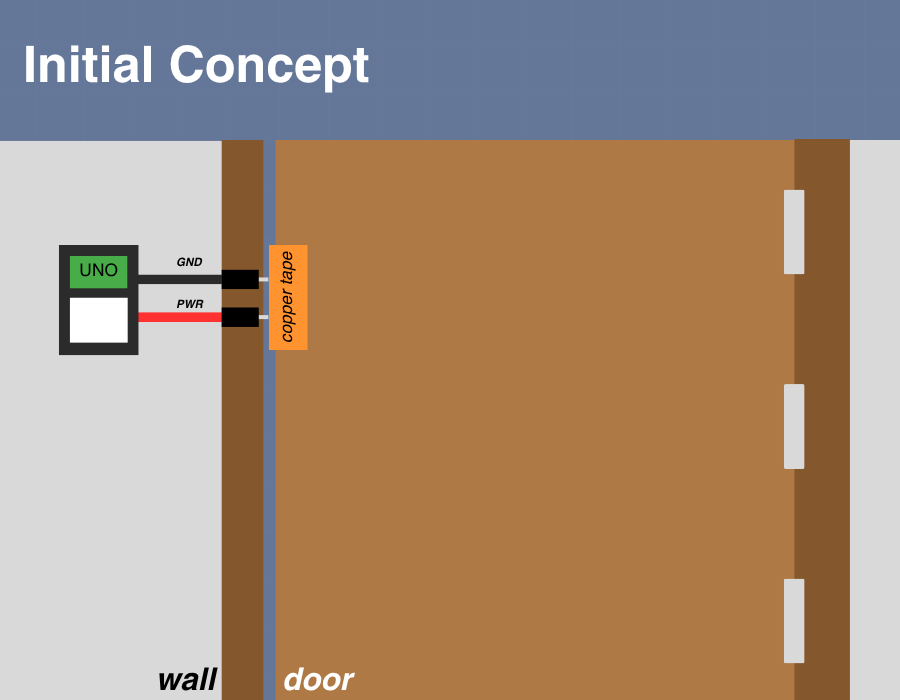
If you’ve seen my previous blog post and the ideas I had for how to construct this thing, you would notice that the final version of the build is very different from the original plan.
There were essentially two major issues going into this idea:
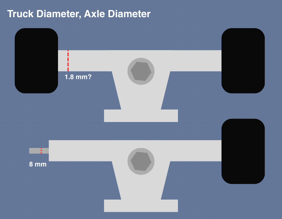
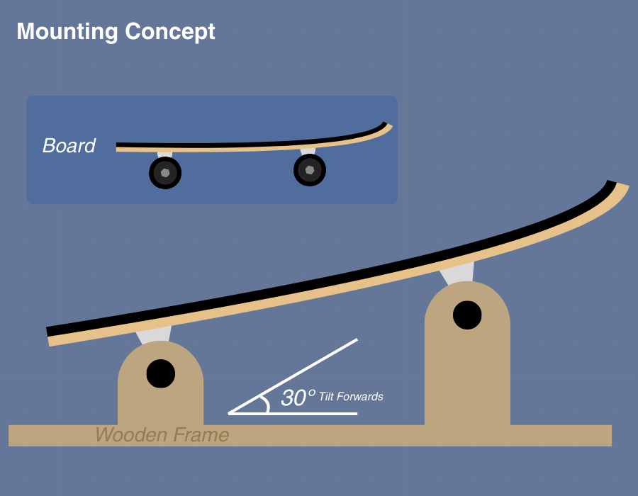
I forgot to consider that the trucks move in more than just one axis, they also lift up (I believe this is because I have RKP trucks); this means the original support columns would hold the trucks still and disallow it from tilting in either direction
I have no idea how to build stuff with wood.
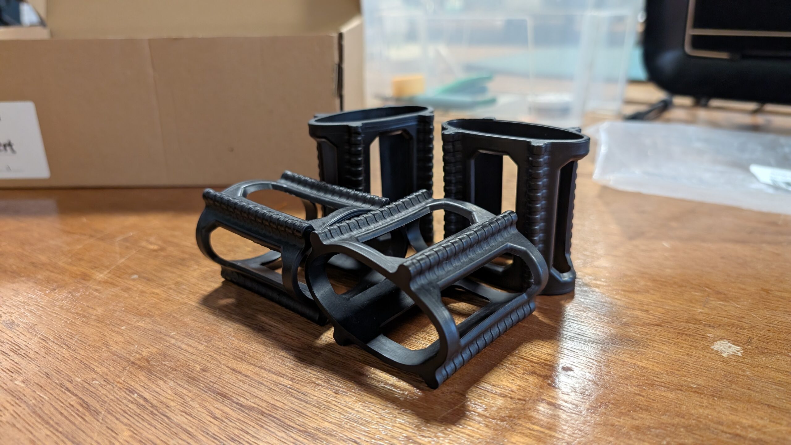
It was actually Dustin that recommended me to search for “skateboard trainers” online instead of “skateboard mounts” because “mounts” were leading me to wall display mounts instead of what I wanted. Searching up “skateboard trainers” gave me these rubber things that I ordered immediately.
Dustin also recommended me to use large zip ties to secure the board in place instead of building a socket for each wheel. This greatly simplified the process and saved me so much time. I am forever grateful to Dustin.
Testing Prototypes
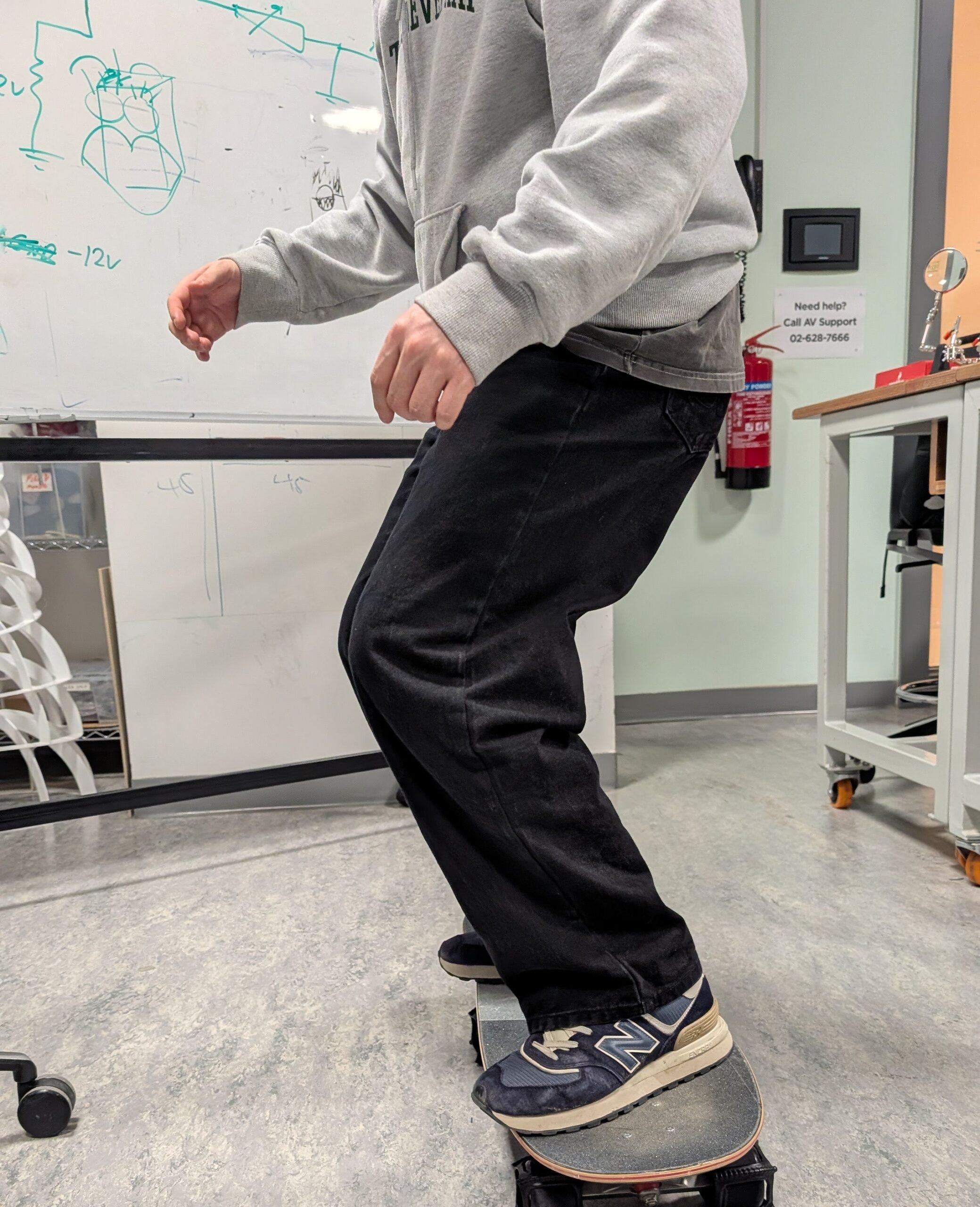
While I was in class, I thought it might be a good idea to see how people interact with the skateboard so far, with just the rubber trainers holding the wheels, so I invited Yongje and Siyona to take a ride on it. When Yongje initially stepped on it, he said some handle bars might make him feel safe but he quickly got comfortable with it. I paid special attention to where he approached getting onto the board and where he was placing his feet. Siyona was initially a little confused on where to place her feet, so this is when I got the idea to add some green indicators on the board for where to stand
It was at this time where Professor Mang strongly advised me against the idea of introducing a forward-leaning angle to the board. This would’ve created a safety nightmare so I decided to make the whole skateboard sit flat. We also measured out the board’s dimensions and the base’s potential dimensions based on that.
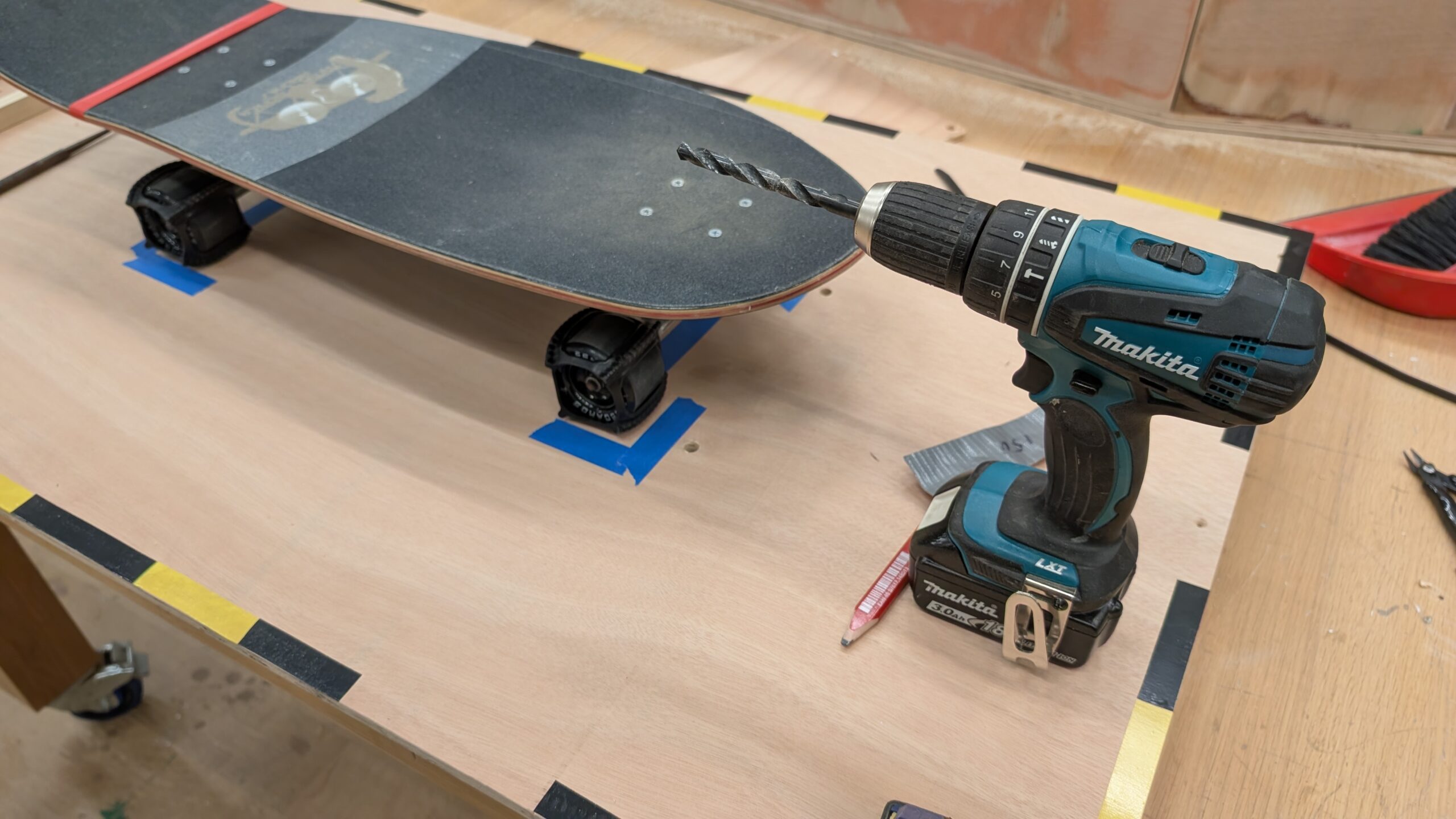
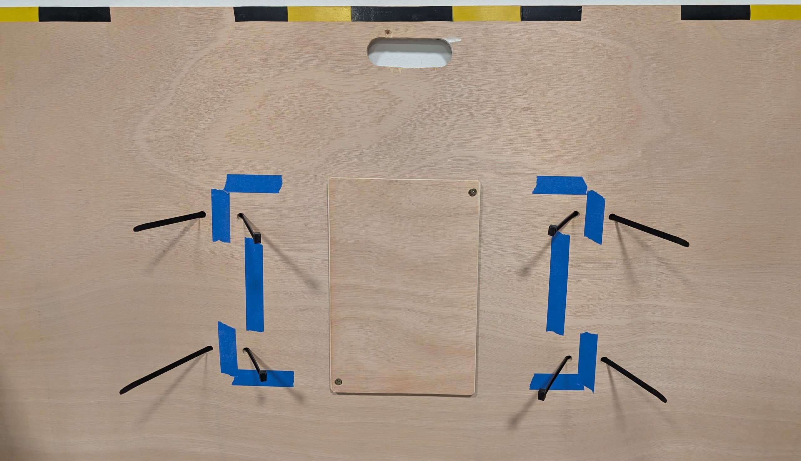
The next day, I went to the scene shop with Prof.Mang to grab a piece of plywood around 126 cm x 72 cm. We sanded it down and I taped a sequence of yellow and black tape as caution lines around the perimeter of the board. I also put down temporary paper tape to indicate where the wheels will go and where the trucks are; this would allow me to drill holes into the
After I had finished planing out the base, I had my good friend Clara step onto it to see how she would interact with it. This is what I documented for the week 13 User Testing so I’ll keep it brief; Clara has never stood on a skateboard before and this was her first time. I started getting an idea of where people who’ve never skateboarded typically stand.
Then I got a video from further away to see how she was naturally adjusting to the board as she got on. I pay special attention to how people bend their knees and adjust their arms when they’re leaning on the board.
Construction & Arduino Integration
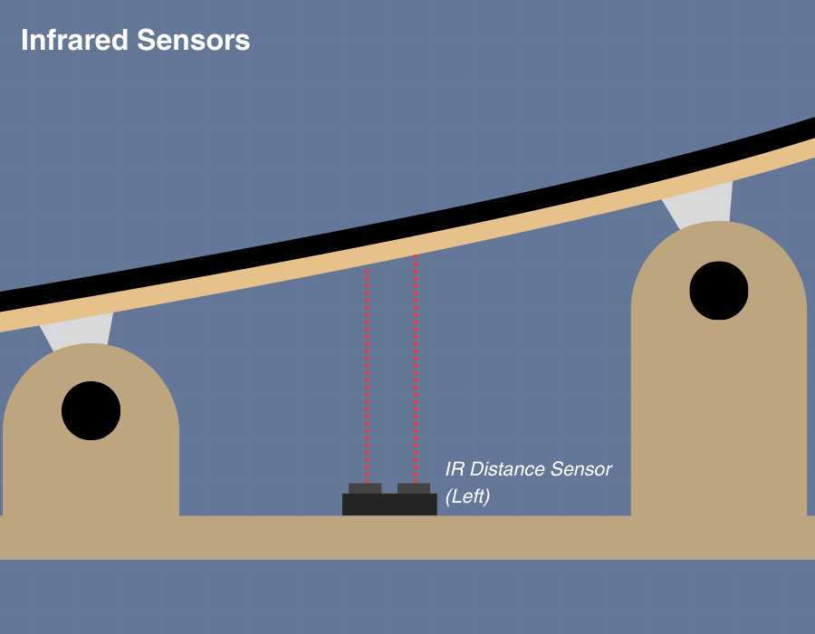
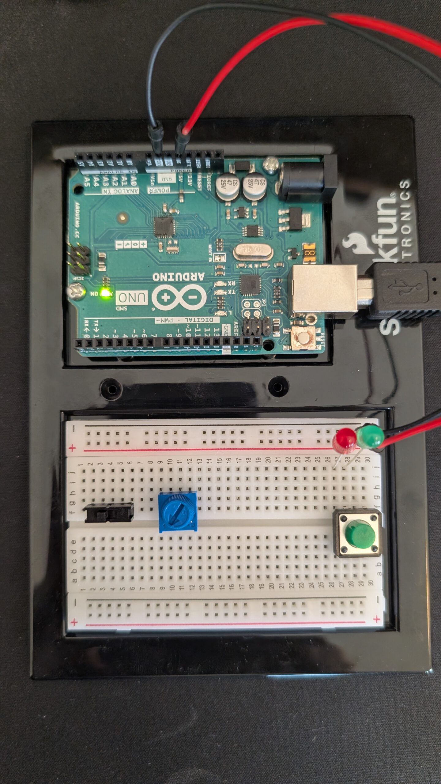
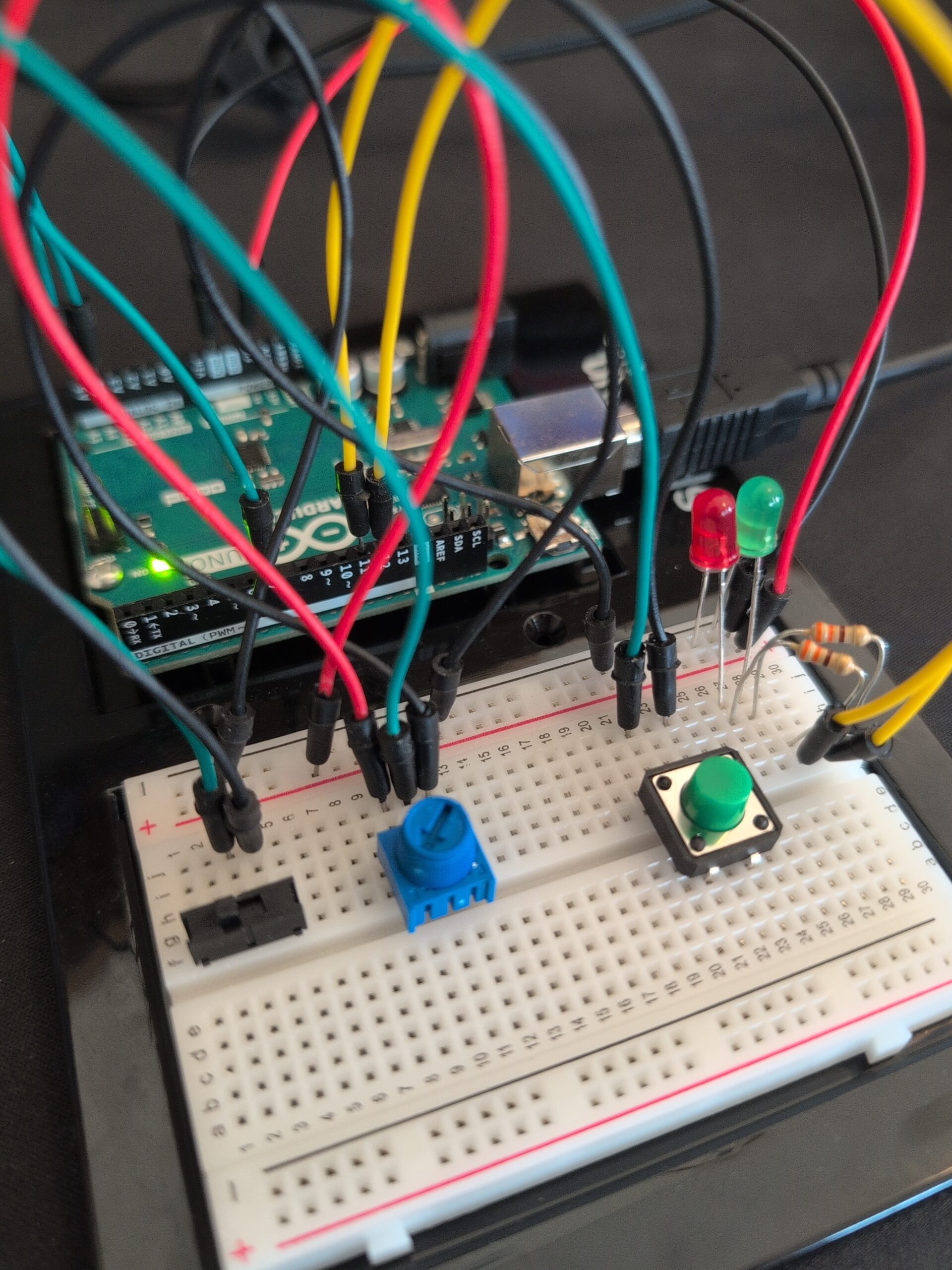
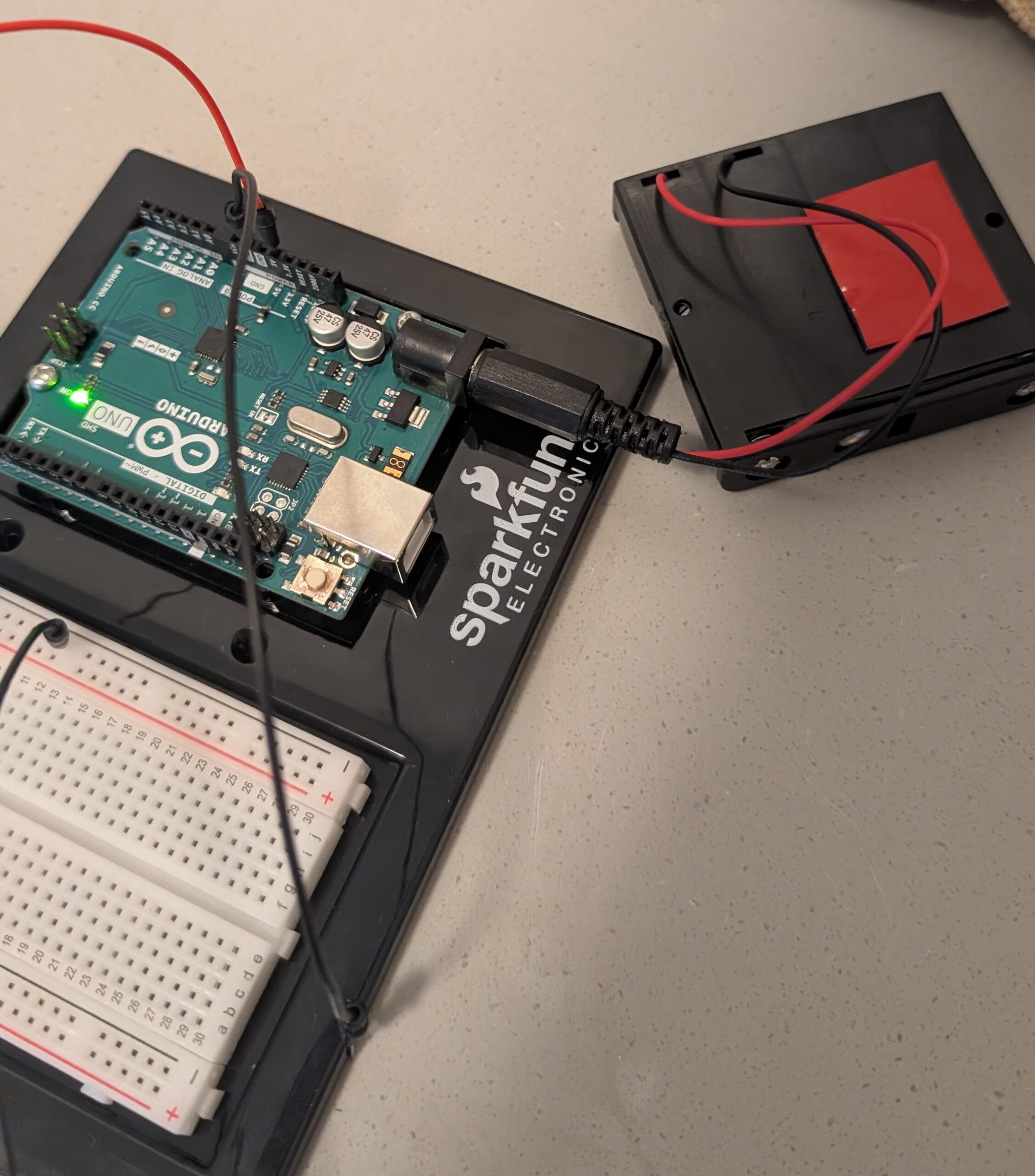
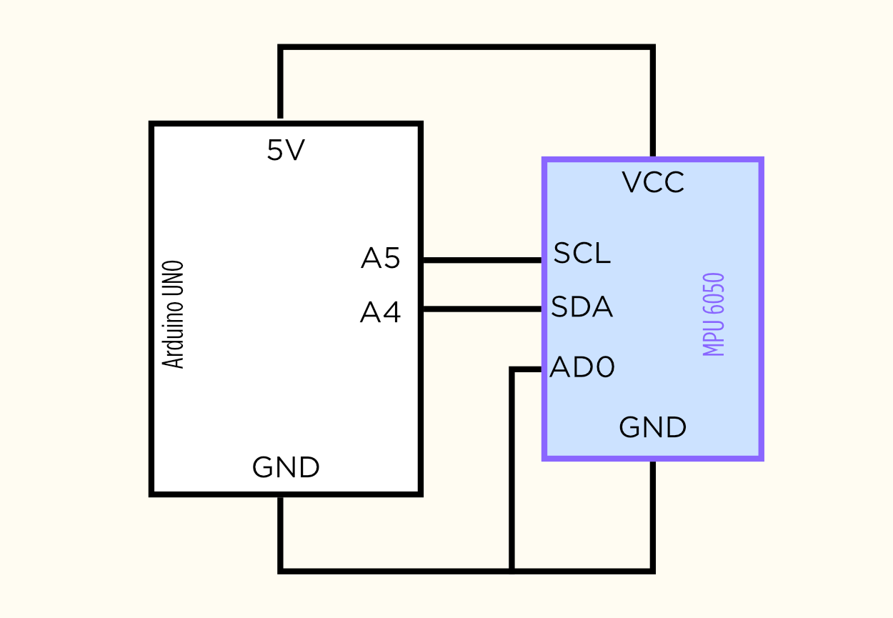
For this project, I needed an accelerometer for its ability to detect tilt. I bought my Accelerometers off of Amazon instead of renting one from the connect2 system because I wanted to keep it for my project after the showcase. The
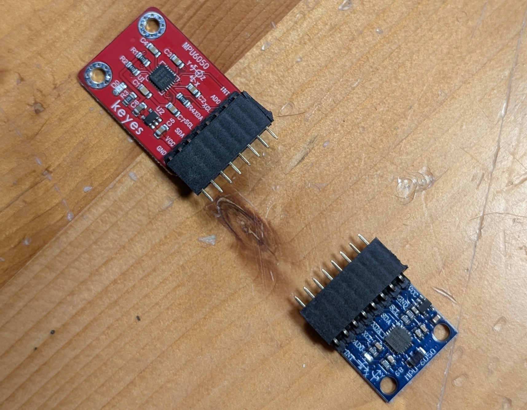
accelerometer I bought was the HiLetGo MPU6050 (the blue one) and it worked fantastic despite not being from one of the larger brands.
However, the accelerometer did not come pre-soldered so I had to solder it myself. Thankfully Professor Shiloh did a fantastic job of teaching me everything about soldering and I was able to solder everything really well by myself.
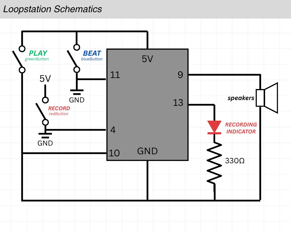
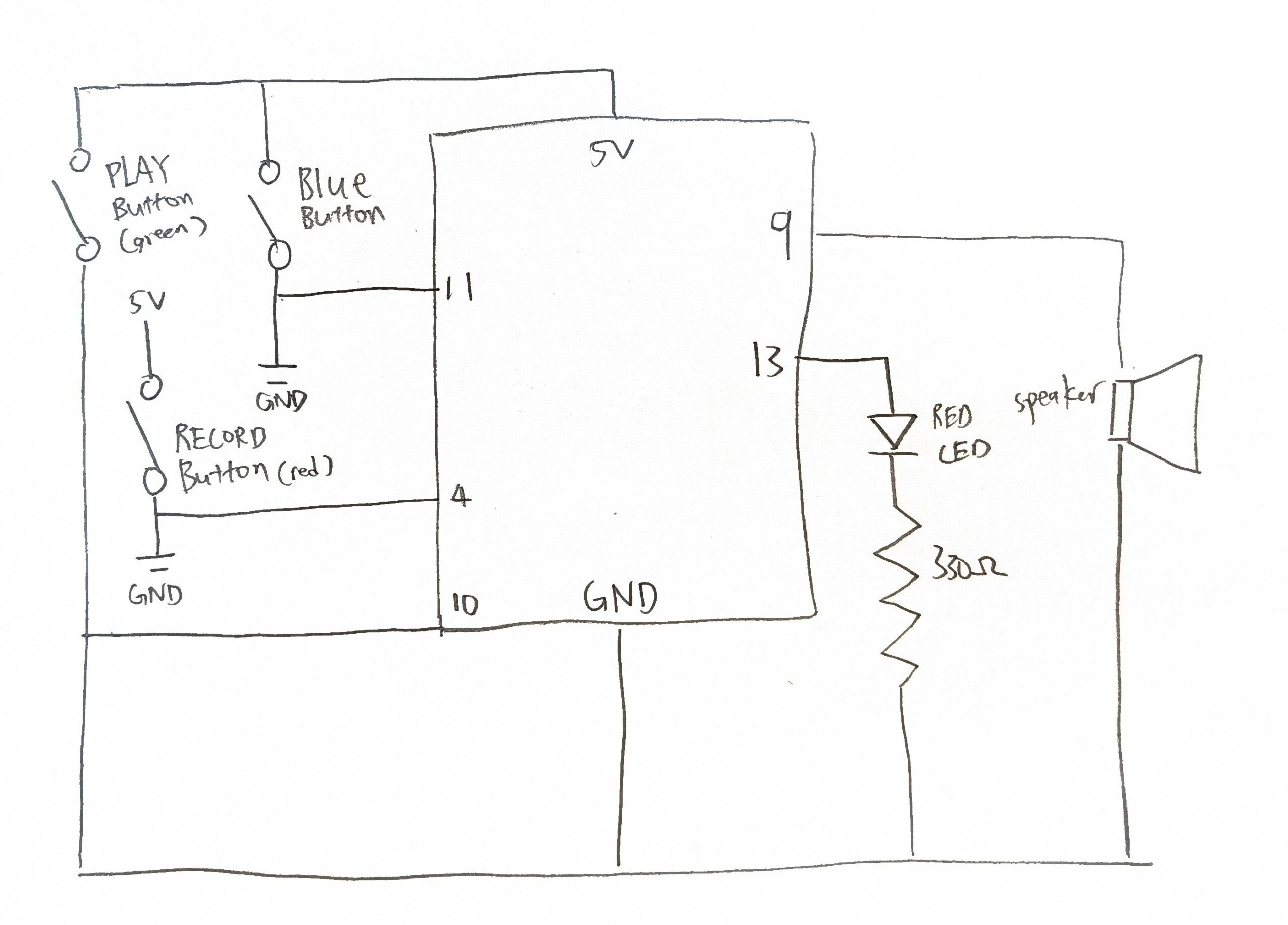
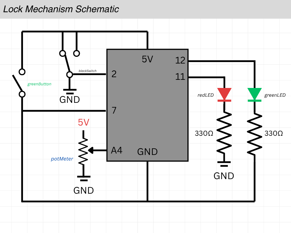
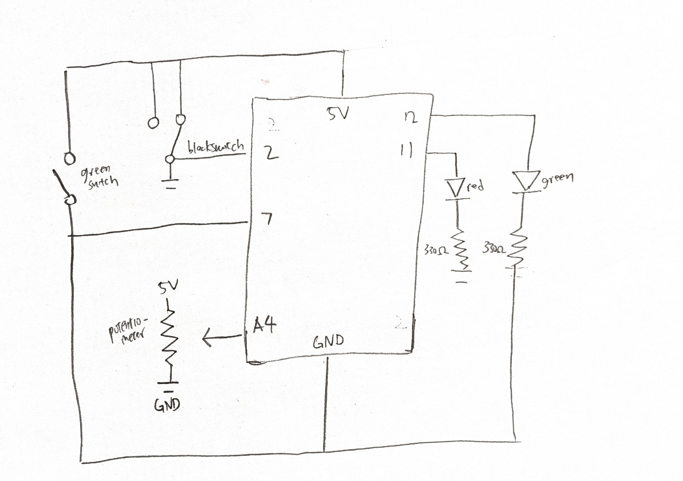
Here’s my vector-hand drawn Affinity schematic for the circuits:
After that day, I spent a lot of time in the scene shop with Tony working on the base of my project. Carrying it by its sides was getting very tiring so I decided to cut a handle with the jigsaw. In my practice cuts I was not cutting very clean circular shapes at the ends of the handle so I decided to use a hole saw for the corners and use the jigsaw to cut the straights instead. The handle may not have been necessary but it was much more convenient to transport the big rectangular base after I made it.
Then was the task of drilling holes in the base for the zip ties to tie down the board to the base. The original idea was to tie it to the trucks but the rubber skateboard trainers actually make for a perfect place for the ziptie to slip through. I measured roughly where the zip ties would have to go through for maximum stability while allowing slight lift for the RKP trucks to tilt, marked it with a pencil, and then drilled it out with a 9.5mm bit. This part was very challenging since it was my first time woodworking but it was a very rewarding experience; I was very glad I challenged myself to make this project.
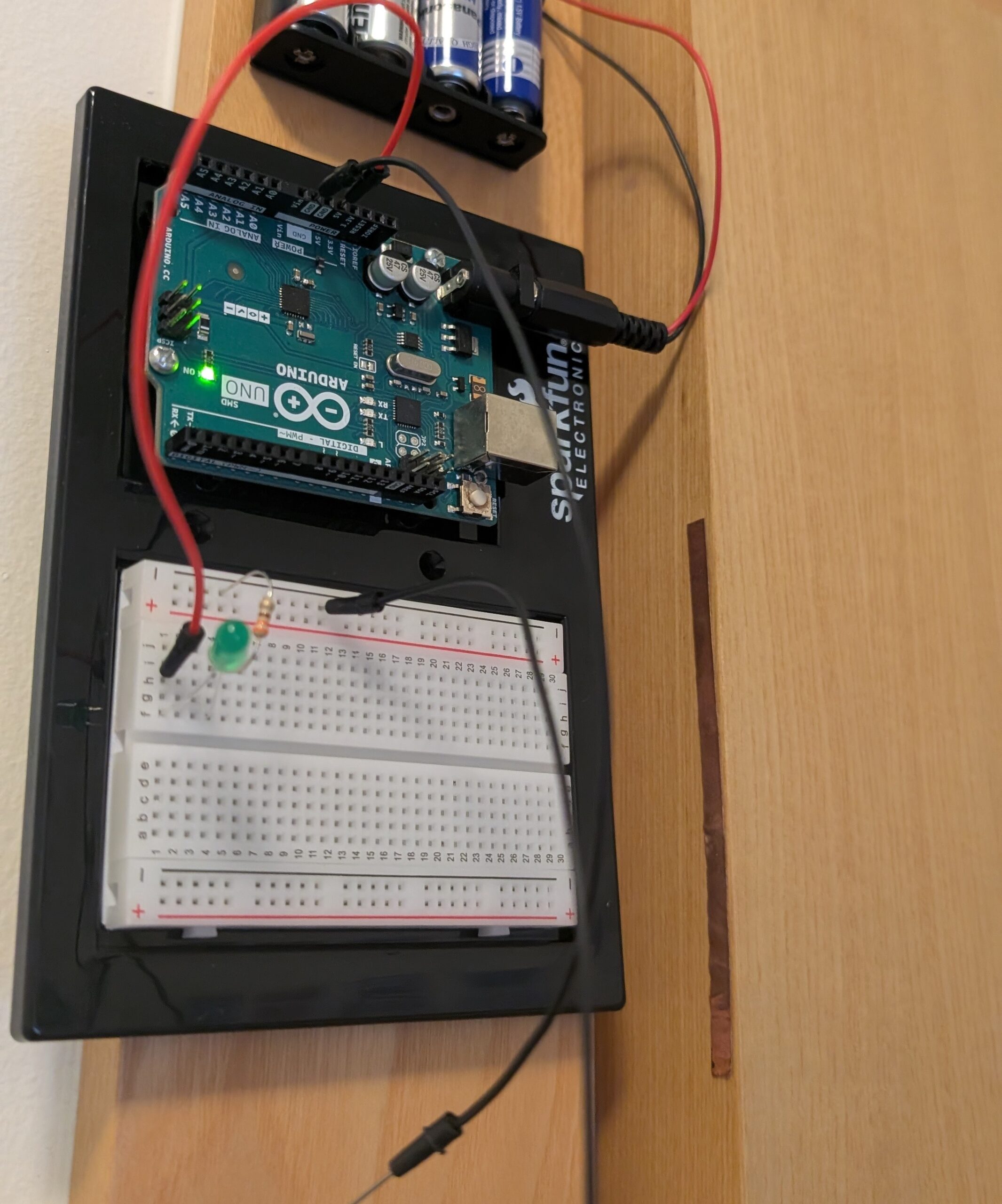
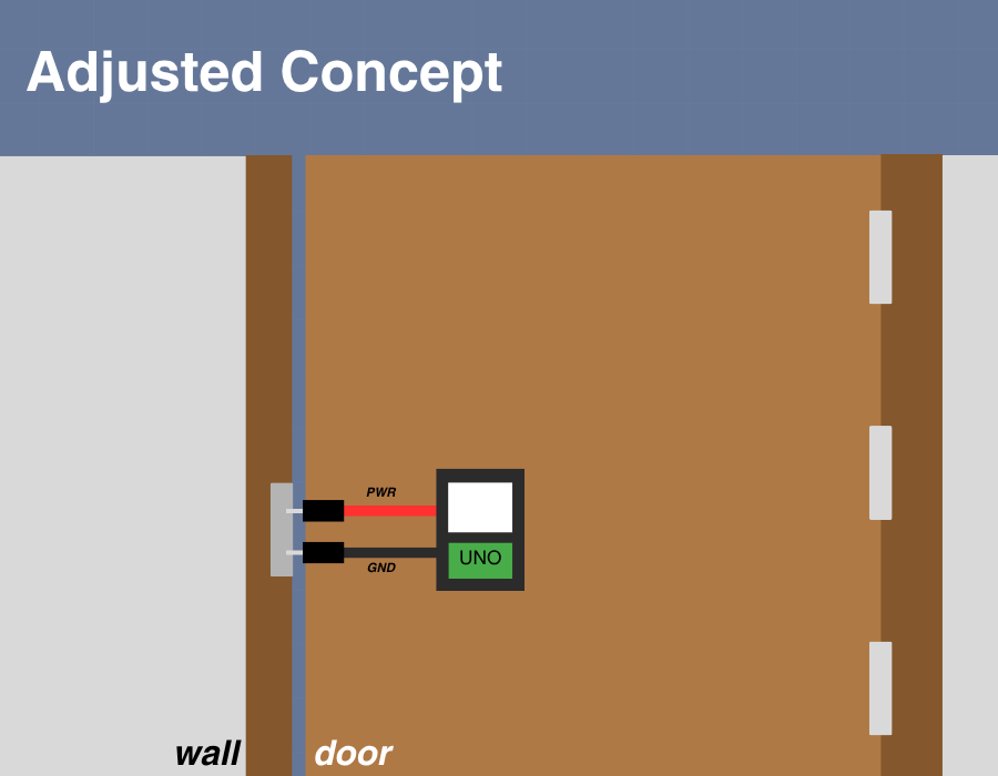
Professor Mang recommended that I make a small plank of wood that would house my Arduino and be semi-locked under my board but removable at any time so I decided to make that; I started by grabbing a small plank and sanding it down thoroughly since I was going to be handling it very often. Then I moved onto drilling two holes in opposite corners to each other and marking the holes on the main base with pencil. I then screwed in two small golden screws to hook onto the small modular piece. It turned out pretty great, and it even stays on while held vertically; although I’m not sure if the added weight from the Arduino and breadboard would allow that once those are mounted on.
You might have also noticed that I made a handle for the base; that took a really long time but I love how it turned out.
Software Development
I didn’t really have a clear idea of what the game would actually look like for most of the semester; and yes, I’ve been planning this since day one. I even
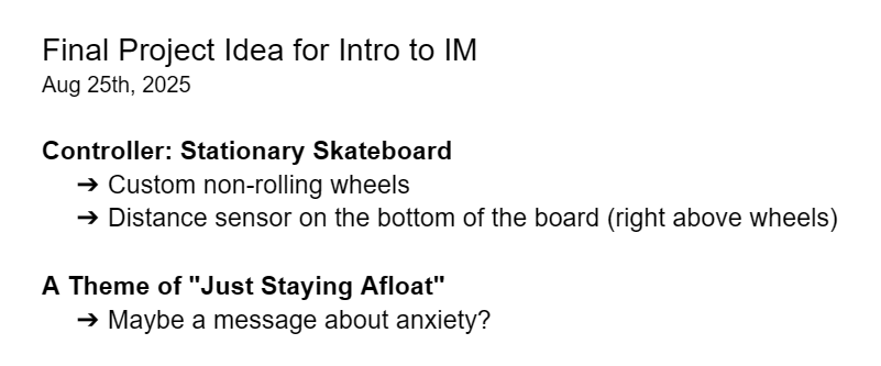
wrote it down on a doc in my drive.
Sure I had a few ideas, but nothing that really excited me. I wanted a game that involved only side to side movement, but it would still be engaging and dynamic.
I thought about games like Pong, Subway Surfers, and even the “catching random things falling out of the sky” genre, but none of these sounded fun. Pong would be easy to do but I’m not sure it would be very fun playing against a wall that bounces the wall back by oneself; the reason why the midterm co-op mode worked was because having a second player added a whole ‘nother dimension to the design.
I ended up having this great idea for a bullet-hell inspired 2D spaceship shooter; I didn’t want it to be too stressful so there wouldn’t actually be bullet hell intensity but there would still be obstacles you need to steer away from. So I got to work.
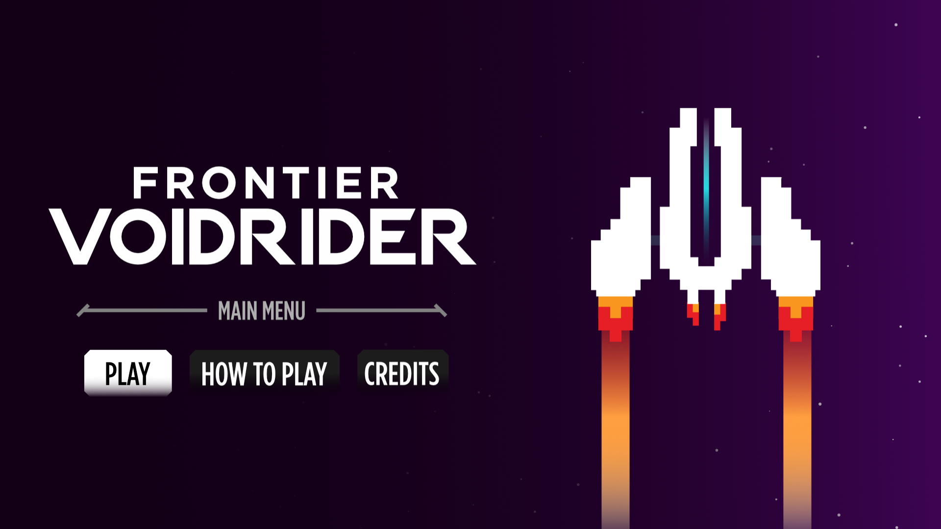
Interface Design
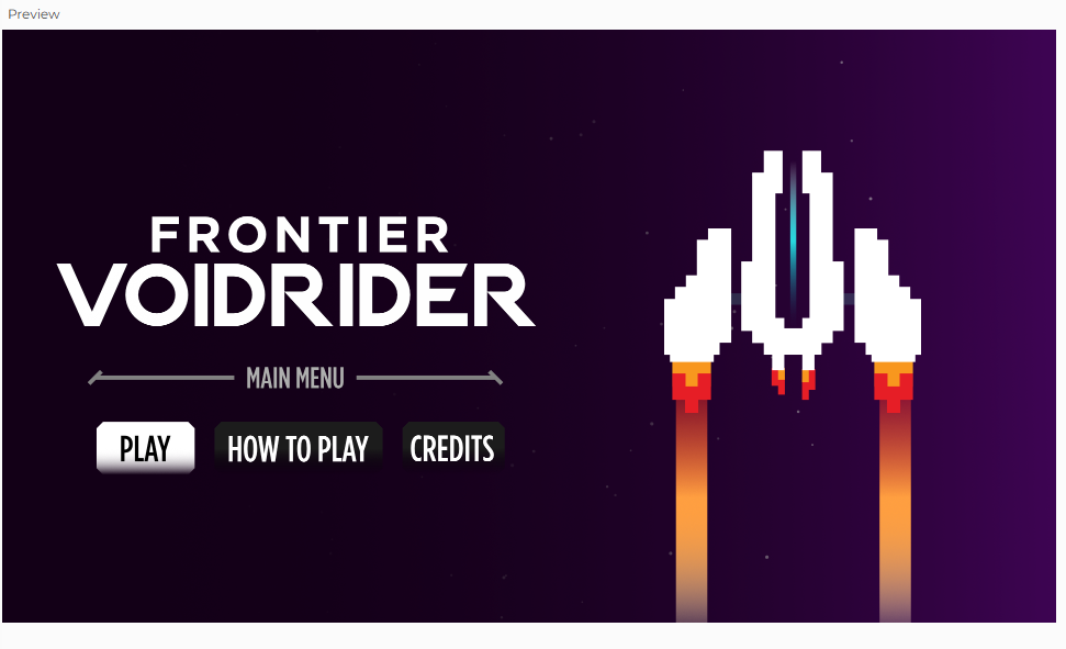
The interface was inspired by many different things. A lot of the UI is inspired by my midterm project; I thought it would be nice to have a coherent menu system between them. It made sense since I also reused my code for screen and button management for this project. I loved how the title screen turned out. I had been designing in portrait mode all semester because portrait feels more casual and informal but I knew this project had to get the full landscape treatment and be placed on a big display.

The “Hull Integrity” health bar is inspired by one of my favorite games of all time, Titanfall 2. It works perfectly here as the
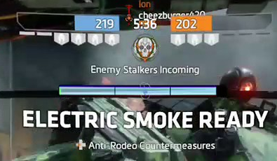
health for the ship. I think it looks great too, especially with the blinking effect when your ship is “doomed.”
So much of this project was inspired by the Titanfall universe and the amazing design from the team behind it. I really hope that my designs make any potential Titanfall fans that play this project happy; it sure made me happy learning to recreate it.
Sprite Design
All the sprites were custom drawn by me in Affinity using vector tools. I had a lot of fun designing the sprites for the game. I really loved creating separate sprites for the spaceship based on the damage it had taken. I think it adds a lot to the visual communication to the player, especially for them to take more caution.
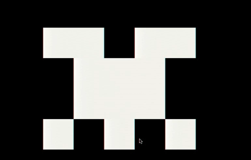
The parasite alien sprites were inspired by Casey Reas’ Eyeo talk on chance operations all the way back from the Week 2 reading; it’s from around 28:00 minutes in where he creates these little symmetrical space invaders-looking aliens. I have an image below of one of the ones Casey made and one I made that was inspired by it. All of the parasite designs were strongly inspired by examples shown in that Eyeo talk; I thought it’d be a nice callback to I believe was our first ever reading assignment.
The asteroid sprites were the one I was least proud of, I really struggled to make unique variations so some of them look a lot nicer than the others. I’ve always struggled to depict nature so this stressed me out a lot. I only made 3 of these so unfortunately you see a lot of repeats.
Sound Design
The sound design for this game was quite challenging. For one, the game is set in space— there is no sound in space. For two, I wanted to avoid generic Star Wars-like sounds.
I chose a kickdrum for the railgun shooting sound because I knew a bass-y sound would be less annoying to listen to on repeat than something high pitched. I had a big emphasis on subtle sound design in this project.
Speaking of subtle, I really cared to add things like ambient spaceship-humming and stuff like a sci-fi bridge sound effect on loop when you’re on the menu screen. I thought the bridge sounds with the ambient music in combination turned out amazing; you could listen to some pretty immersive sounds while you browsed the menus.
I also had the countdown sound effect I used in my midterm project return for this one, used in the exact same way — to count the player down before the game starts.
Near the very end of developing this game, I found some voice line files from Titanfall 2 where the mech, BT, says to the pilot “Warning. Major Hull Damage Detected” and “Warning. Heavy Damage Sustained.” This really added to the immersion of the gameplay and I really hope people will like it.
Misc. Design Choices
I could go on forever about the many little decisions I made in an effort to make this game excellent but I’ll stick with the most practical things I designed.
I placed calibration settings in the “How To Play” menu so players can calibrate while they’re on the same page where they try to understand the controls and objectives.
I made all the menu navigation possible with just a mouse; so even if you don’t have a keyboard in your hands, you can just click RMB to go back to the main menu; but if you do have a keyboard available you can also press CTRL to go back (ESC would exit fullscreen and I don’t think I can remove that from the browser).
Creating Custom Keybinds
I had a lot of fun setting up the serial connection because I split everything up into separate functions I can call and assigned each of them to a keybind. I thought the “Connect to Arduino” buttons I was seeing looked so ugly and felt so unintuitive, so I came up with my own solution.
I needed a button to quickly reset the current angle to C so I assigned “C” to become my calibrated button. It was chosen because the word calibrate starts with a C, which became a reference point that was easy to remember.
“X” was used to connect/disconnect the serial connection. It felt SO much more practical than having an onscreen button. “X’ was chosen purely because it was next to “C.”
And lastly, “B” to open the debug menu. This really made it feel like a real developed video game.
How this was Made (AI Utilization):
I asked ChatGPT 5.1 to help me set up the accelerometer I bought off of Amazon. It helped me understand what each pin did and gave me the library I needed to download for my MPU6050; afterwards, It helped me debug my serial connection code that I copied from the lecture notes and helped me add a P5 to Arduino transmission that would tell it to zero itself and calibrate the current angle to 0 degrees. ChatGPT 5.1 was a major help for setting up the serial connection.
ChatGPT 5.1 was also used to debug everything when I couldn’t figure it out. It recommended a lot of different approaches to program things like enemy spawning. Through the debugging process I ended up learning really fast because it answered all my questions like”why would you fix it that way?” or “are you sure you’re right? doesn’t this function() work like this?” in a really clear and precise manner.
Final Words:
This project was genuinely one of the most fun projects I’ve worked on in my three years at NYUAD. Through this project alone, I learned so much about woodworking with Tony in the scene shop, soldering with Professor Shiloh, and general project management throughout every step.
I want to give a very special thank you to Tony, Dustin, Professor Shiloh, Professor Ang for general guidance throughout the project, whether it was teaching me new skills or even training me in new tools. This project wouldn’t have been possible without them.
I also want to thank my playtesters:
Gauhar Meiram, Clara Juong, Yongje Jeon, Siyona Goel