Week 14 — Final project

Concept Description

My project is a physical digital simulator that showcases the UAE across three eras: the past, the present, and the imagined future. The idea came from listening to my grandfather’s stories about how he used to live, and how different life is now. Seeing how quickly the UAE developed made me wonder how the future will look. I wanted to create an experience where people can explore this progression visually by interacting with a real physical device.

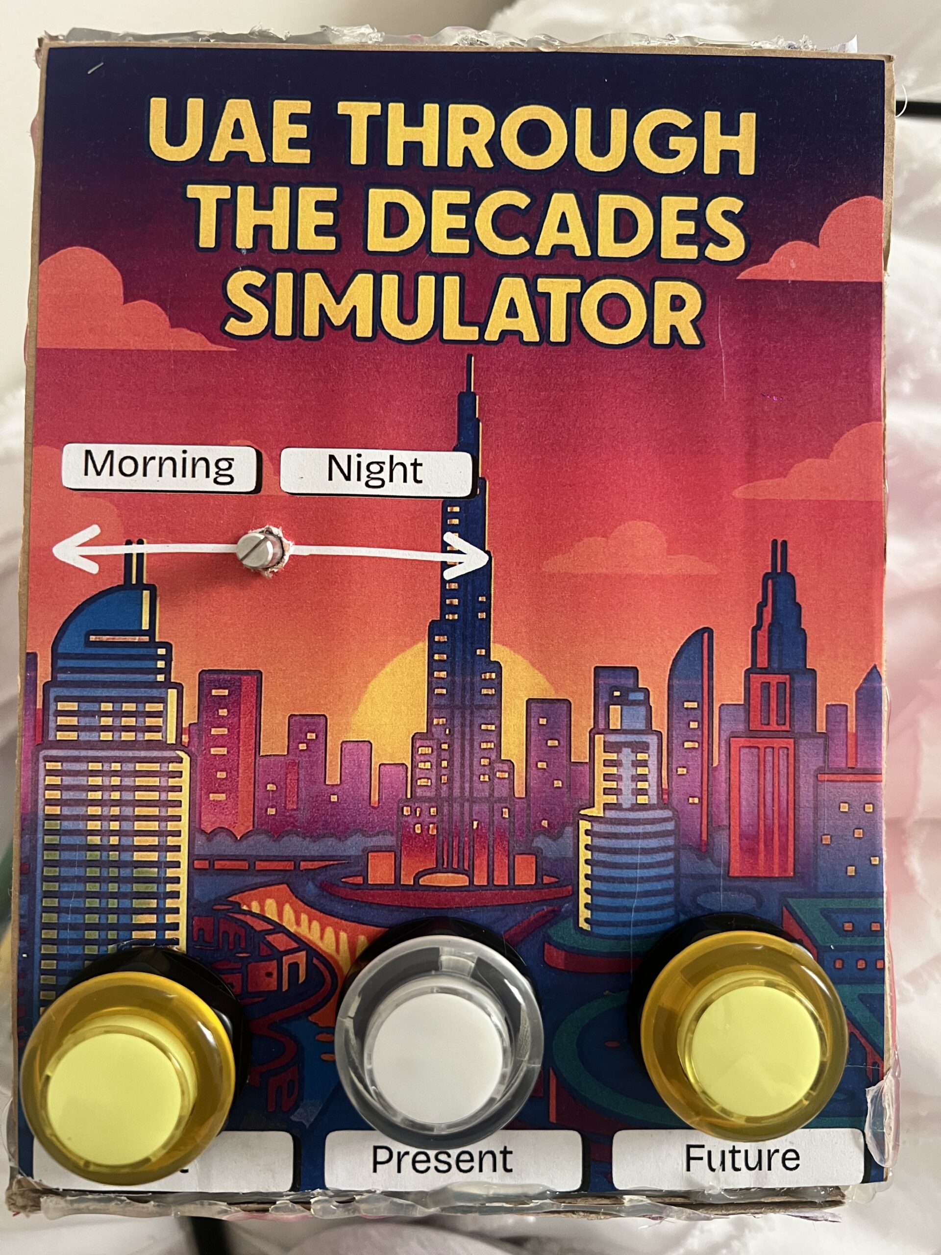
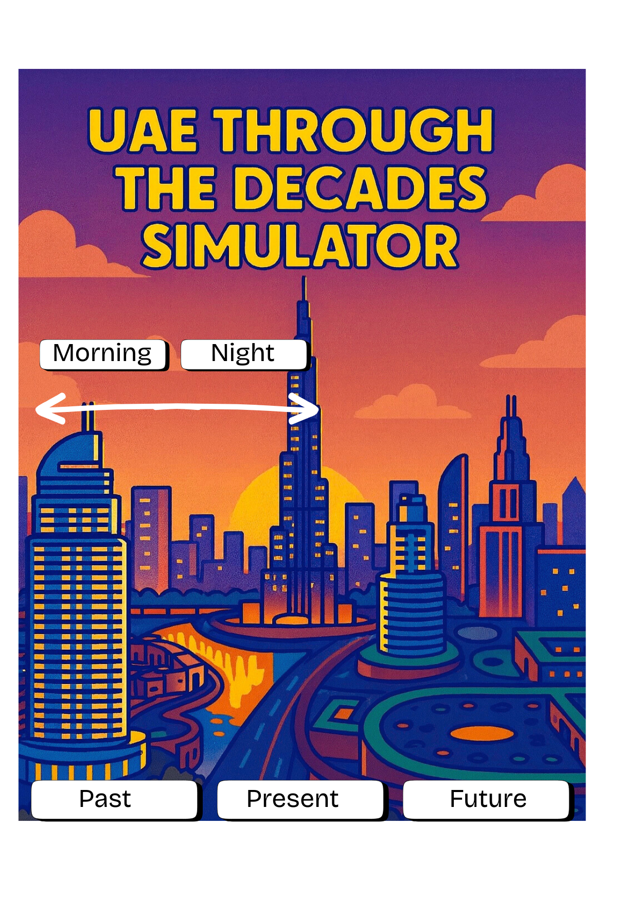
The simulator lets users switch between the three eras using physical buttons, and then cycle through multiple images for each era. A potentiometer controls the transition between morning and night, allowing people to view each scene in two different lighting conditions. Overall, the goal of my concept is to let users “travel through time” and explore how the UAE evolved and how it might continue to evolve.

How the Implementation Works

The project works through a simple but effective communication between Arduino and p5.js:

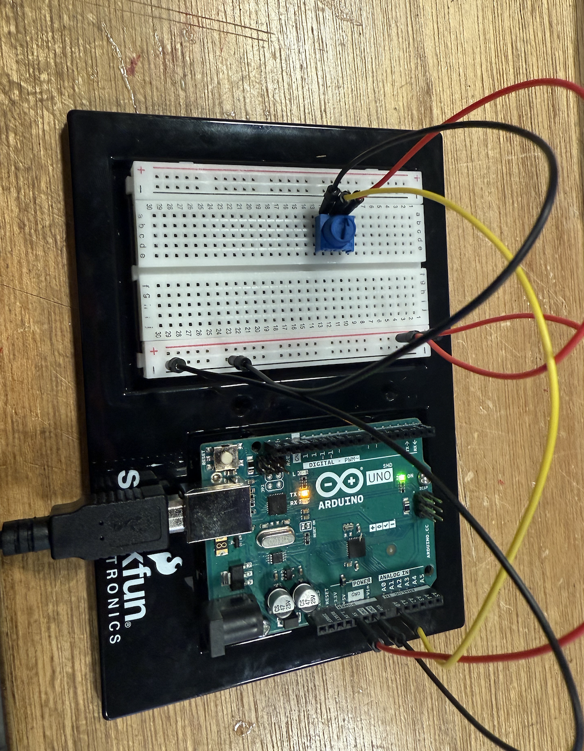
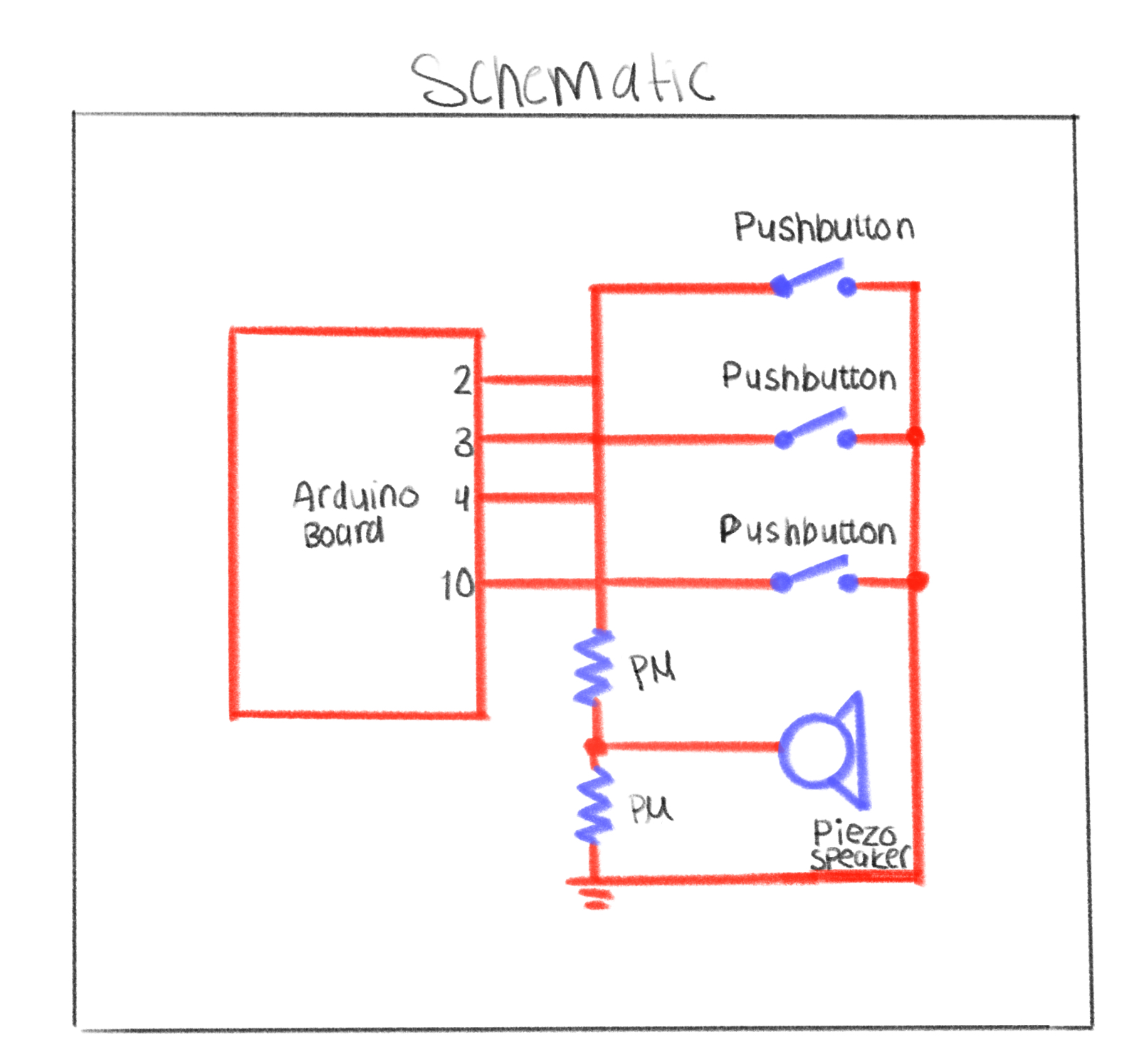
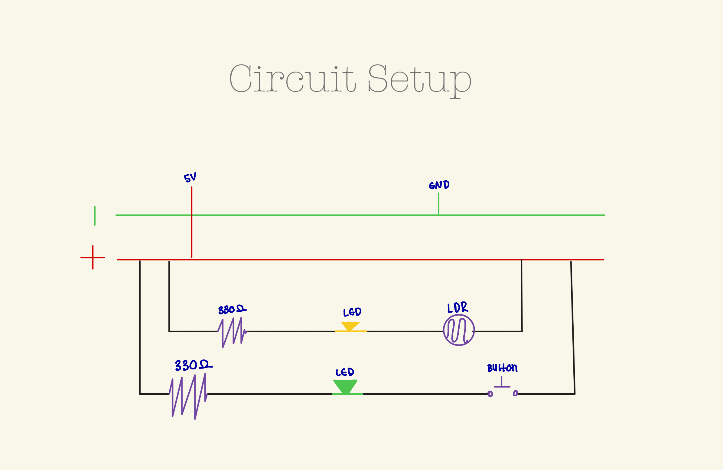
• The Arduino has three buttons (Past, Present, Future) and a potentiometer.

• When the user presses a button, Arduino sends data to p5.js identifying the era and which image should appear.

• When the user turns the potentiometer, Arduino sends a number from 0–1023, which p5.js interprets as morning vs. night.

• p5.js displays the correct image from a set of 18 total images (3 eras × 3 photos × 2 lighting versions).

• Everything is controlled physically the user doesn’t interact with the laptop at all after connecting.

I intentionally kept the interaction simple so it would be easy for younger users (including my younger brother) to understand instantly.

IMG_0934

 Description of Interaction Design

The interaction is entirely physical and designed to be intuitive:

Three buttons, each labeled clearly: Past, Present, Future.

• Pressing a button cycles through three images per era.

• The potentiometer smoothly switches the scene from morning to night.

• No touchscreen interaction the laptop only displays the images.

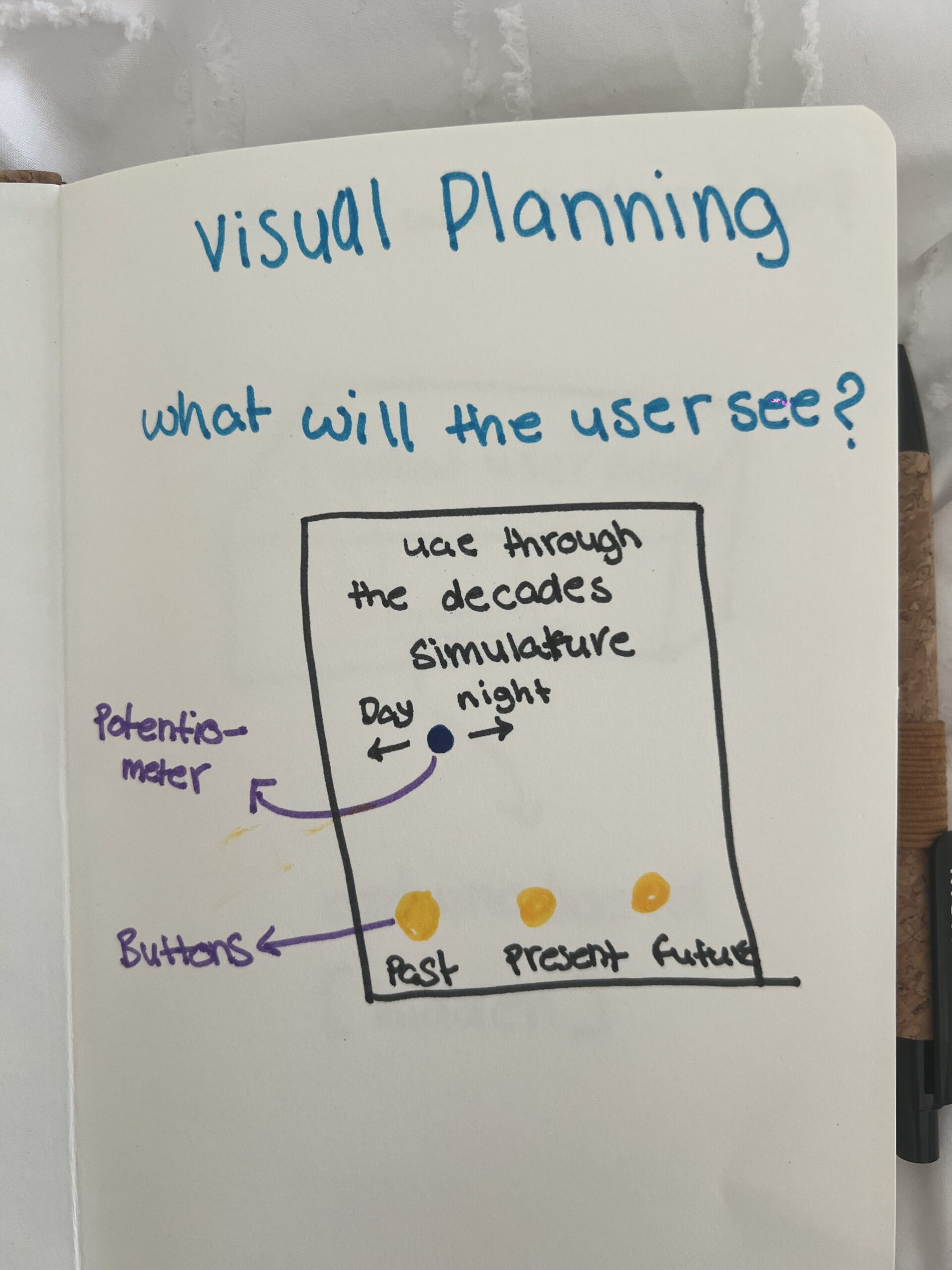
My goal was to make the mapping extremely obvious. Every person who tested the project understood the basic interaction immediately because the controls directly match the results on the screen. The only part that took a few seconds to discover was that each button can be pressed multiple times to cycle through all images, but users figured it out naturally by experimenting.

Description of Arduino Code (with link/summary)

The Arduino code is fairly simple. It:

• Reads the state of three buttons using INPUT_PULLUP

• Reads a potentiometer value (0–1023)

• Tracks which era is active

• Tracks how many times the user pressed each button (to rotate through 3 images)

// pins
const int pastBtn    = 2;   // Button 1 Past UAE
const int presentBtn = 3;   // Button 2  Present UAE
const int futureBtn  = 4;   // Button 3  Future UAE
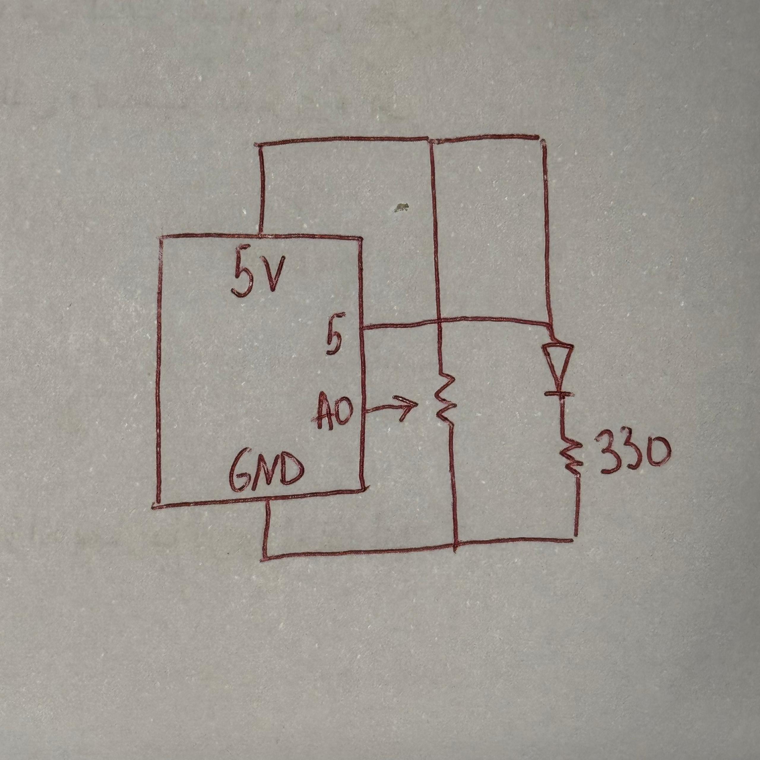
const int potPin     = A0;  // Potentiometer day/night

// variables
int era = 0;       // 0 = past, 1 = present, 2 = future
int imgIndex = 0;  // 0, 1, 2

bool pastPrev    = HIGH;
bool presentPrev = HIGH;
bool futurePrev  = HIGH;

void setup() {
  Serial.begin(9600);

  pinMode(pastBtn, INPUT_PULLUP);
  pinMode(presentBtn, INPUT_PULLUP);
  pinMode(futureBtn, INPUT_PULLUP);
}

void loop() {
  bool pastState    = digitalRead(pastBtn);
  bool presentState = digitalRead(presentBtn);
  bool futureState  = digitalRead(futureBtn);

  if (pastPrev == HIGH && pastState == LOW) {
    era = 0;
    imgIndex = (imgIndex + 1) % 3;
    sendData();
    delay(200);
  }

  if (presentPrev == HIGH && presentState == LOW) {
    era = 1;
    imgIndex = (imgIndex + 1) % 3;
    sendData();
    delay(200);
  }

  if (futurePrev == HIGH && futureState == LOW) {
    era = 2;
    imgIndex = (imgIndex + 1) % 3;
    sendData();
    delay(200);
  }

  pastPrev    = pastState;
  presentPrev = presentState;
  futurePrev  = futureState;

  //  update for the potentiometer
  static unsigned long lastSend = 0;
  if (millis() - lastSend > 200) {
    sendData();
    lastSend = millis();
  }
}
//serial
void sendData() {
  int timeVal = analogRead(potPin); // 0–1023

  Serial.print(era);
  Serial.print(",");
  Serial.print(imgIndex);
  Serial.print(",");
  Serial.println(timeVal);  
}

Description of p5.js Code

The p5.js code handles:

• Displaying all 18 images

• Fading transitions between images

• Scaling images to full screen

• Playing different audio for each era

• Reading serial data from the Arduino

• Switching between three states:

Connect screen

Intro screen

Simulator screen

The images are the main content 18 total files (6 per era). They were made by taking real images of the UAE and using generative AI tools to convert them into cartoon versions. p5.js simply loads these files and displays them according to the physical input.

Communication Between Arduino and p5.js

The communication uses Web Serial:

1. The user clicks once to connect.

2. The browser opens a Serial Port window.

3. After selecting the Arduino, p5.js starts receiving lines of text like:

4. p5.js splits the line into:

• era (0 = past, 1 = present, 2 = future)

• imageIndex (0, 1, or 2)

• timeVal (0–1023, used for day/night)

Every change on the physical device immediately updates the display on screen.

It feels similar to using a game controller or a Joy-Con everything is physical, and the screen responds instantly.

What I’m Proud of

I am most proud of how clean and professional the final project looks.

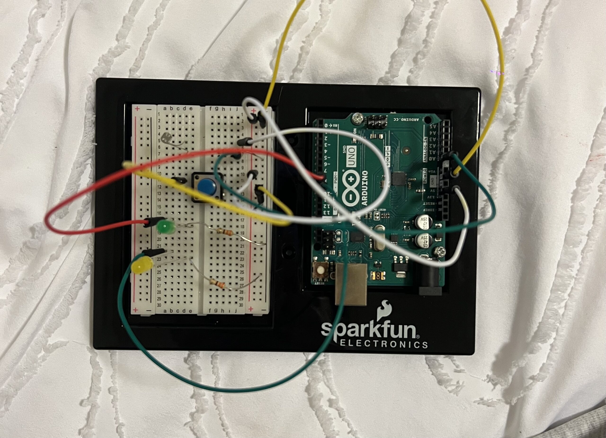
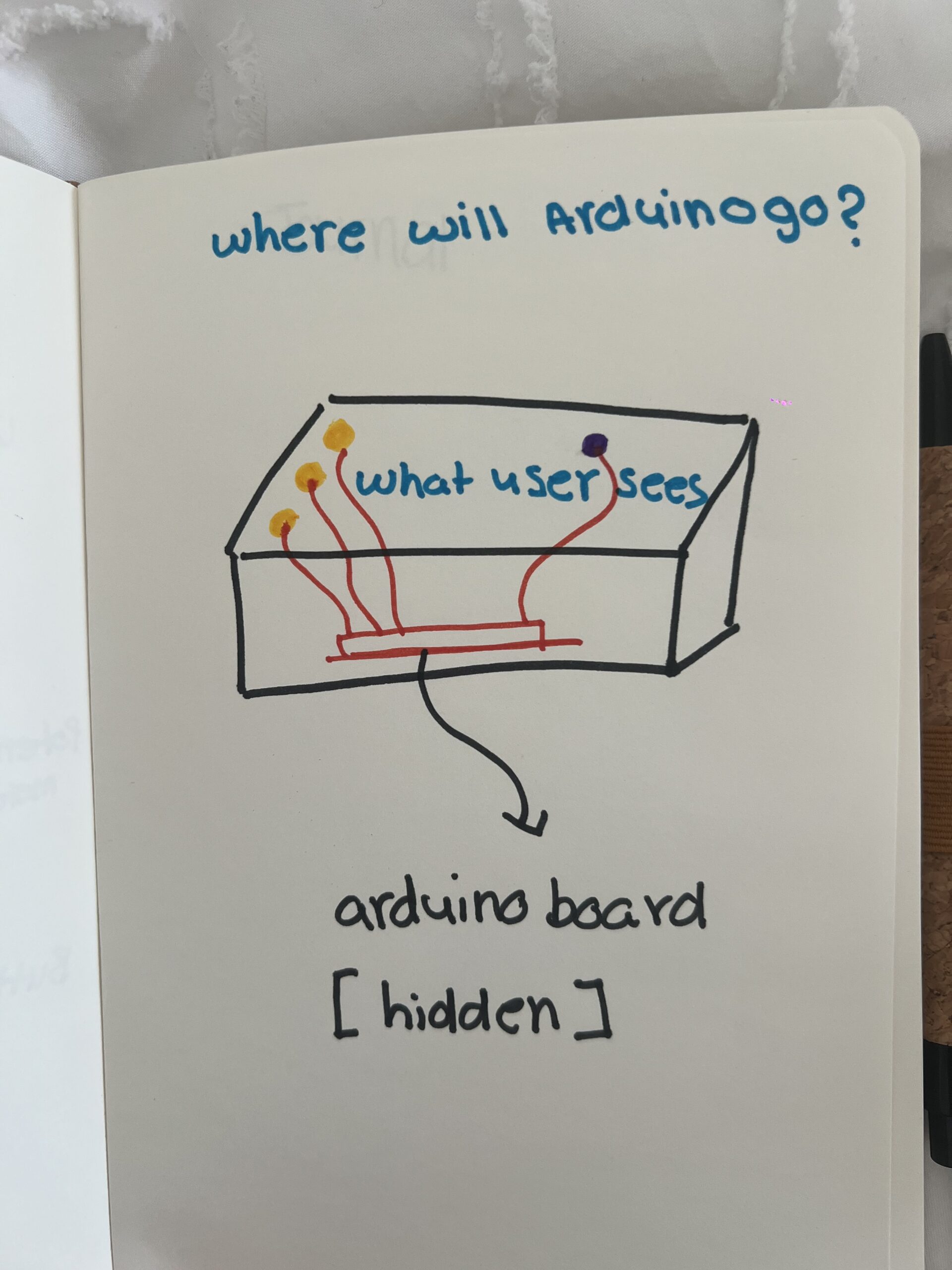
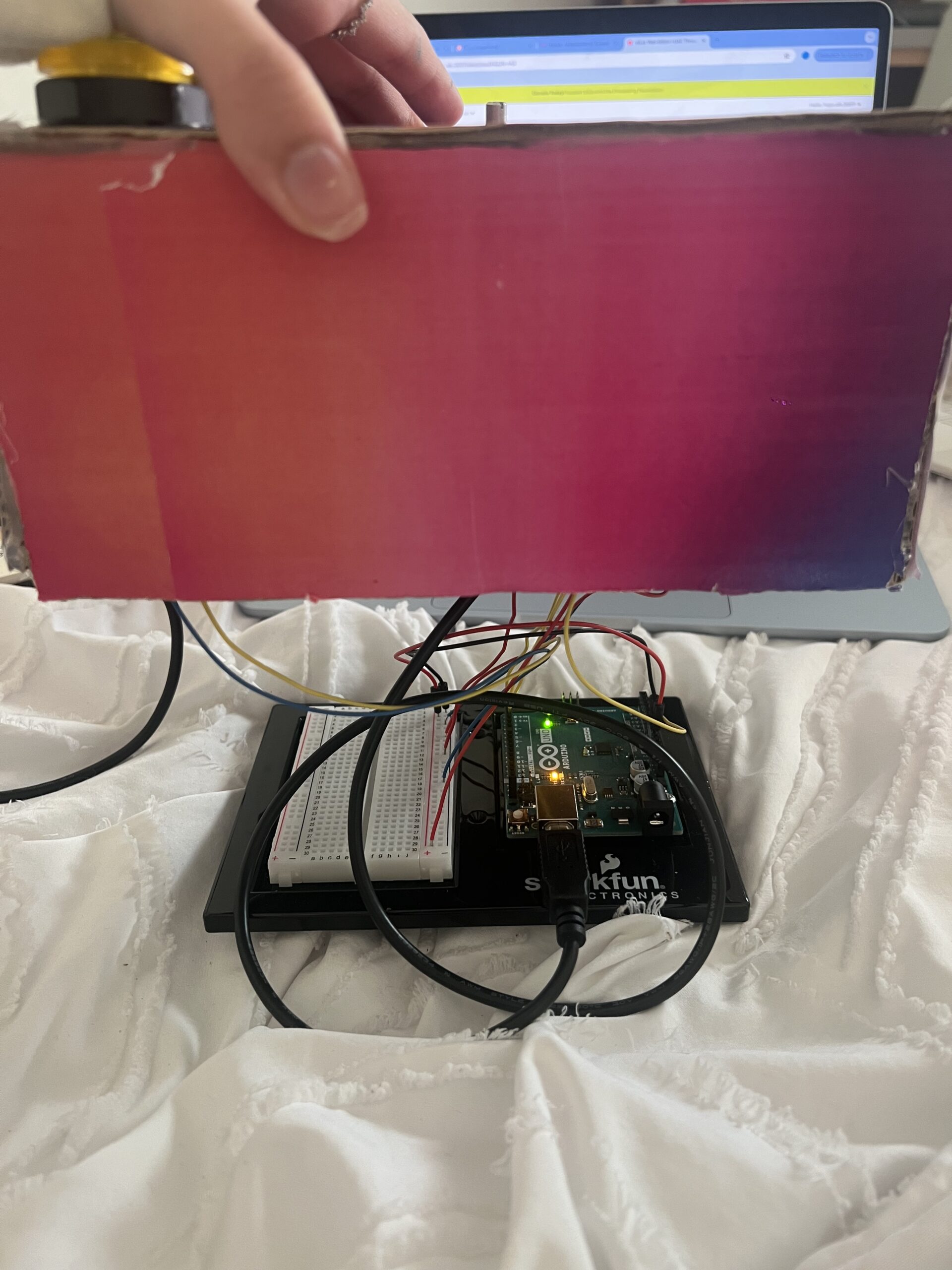
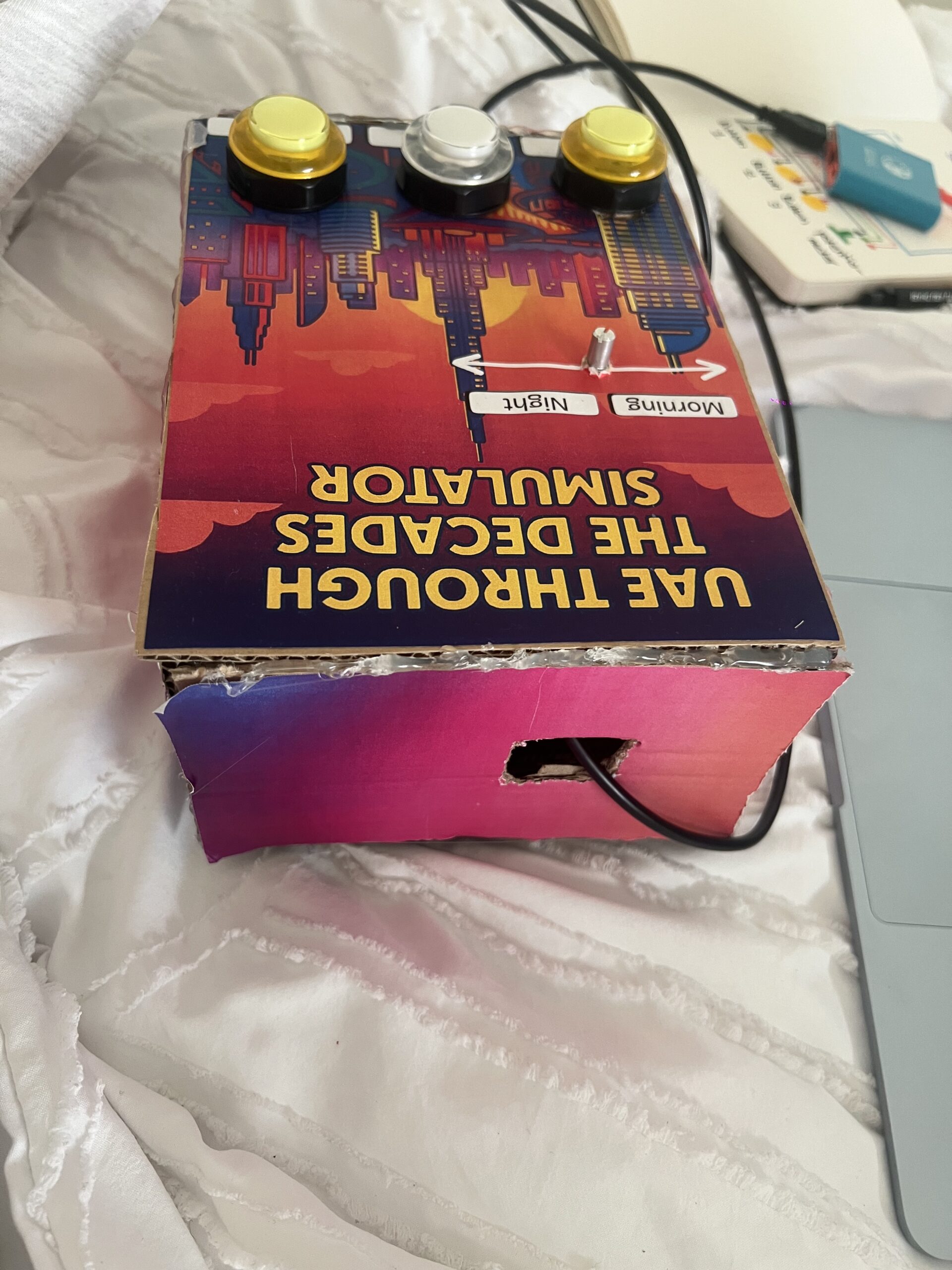
You can’t see any of the wiring  I hid everything neatly inside the cardboard housing. The labeling, colors, and layout make the experience very user-friendly.  I’m also proud of the fact that people were able to figure it out without me saying anything. When I stepped back and just observed, I realized the design communicated itself very clearly, which was exactly my goal.

Looking back at the entire process, I’m genuinely proud of how much I accomplished and how much I learned along the way. At first, organizing all the images felt extremely tedious because I had so many files 18 images total, each with morning and night versions. I also made a small mistake in the naming of the files, and that one mistake made the whole program stop working. I kept getting errors and I couldn’t figure out why. I had to go through each image name one by one, and because the names were long and similar, it was hard to spot the issue. It took me a very long time to fix something that seemed so small, but once I finally found the mistake and everything started working again, it felt very rewarding. I’m also incredibly proud of the physical construction, especially the welding. This was my first time ever welding metal, and it honestly took me one full hour just to weld the first button. The wires kept slipping, the metal didn’t stick properly, and I felt like I was never going to get it. But after doing it over and over, I suddenly got the hang of it, and by the end I was welding each button in about five minutes. Learning a skill like that felt like a big milestone. It really made me feel like I gained a new hands-on skill something I had never tried before in my life.

In the end, the project came together in a way that made me really proud. The wiring is completely hidden, the design is clean and professional-looking, and people were able to interact with it without any instructions. Seeing the final result made all the tedious moments worth it, and it also made me feel more confident in both my coding and physical building abilities.

How This Was Made

I built the physical simulator using:

  • Cardboard and printed graphics
  • Buttons and a potentiometer
  • Metal wires (which I welded for the first time and it took me one full hour to weld my first button!)
  • Arduino and jumper wires

Use of Generative AI

I used AI for visual styling. I first found real photos of the UAE (past, present, and future concept images) and then used AI tools to convert them into cartoon-style illustrations. This helped give the project a consistent artistic style.

I also used AI to help me debug an issue in my p5.js code I sent it the error message and it told me that most probably one of my files name was not the same name I put in the code, which was correct in naming one of my images I accidentally made one of the letters capital and in my code it was lowercase so the code wasn’t running

Design

I used Canva to design the visual aspect

Code Writing & Design

Most of the code is simple enough that I was able to write it myself, but I watched a few YouTube videos to help me understand specific parts, such as Web Serial and Arduino button logic:

Sound source

https://pixabay.com/sound-effects/search/mp3/

Areas for Future Improvement

In the future, I would like to:

• Add more images per era to make the experience richer

• Include more interactive controls, not just day/night

• Maybe add animated elements like moving clouds or cars

• Improve the instruction screen so that users immediately know they can press each button multiple times

• Add richer audio or voice narration explaining the history of the UAE

Week 13 — User Testing

IMG_0847


1. Are they able to figure it out? Where do they get confused and why? Do they understand the mapping between the controls and the experience?

When I tested my project with different people, I noticed that the overall interaction was very easy for them to understand. The three buttons were clearly labeled “Past,” “Present,” and “Future,” and the potentiometer automatically felt like a control for changing between morning and night. I designed the layout to be very straightforward on purpose because I wanted even younger users  like my younger brother to be able to use it without help.

When I let my friend try it without any instructions, she was able to figure out the basic interaction immediately. She understood the mapping between the labeled buttons and the changes on the screen. The design helped guide her because I placed each label directly under the button, and the screen clearly showed the UAE environment changing based on the chosen era.

The only part that took her a bit longer to discover was that each button could be pressed multiple times to cycle through three different images. She eventually figured it out on her own by experimenting and playing with it. Most of my friends had the same experience: they understood the main controls right away, but it took some time to realize the buttons could be pressed repeatedly to see more images. Even though it wasn’t immediately obvious, they still learned it naturally without any instructions from me, which made me feel confident that the interaction was intuitive.

2. What parts of the experience are working well? What areas could be improved?

Overall, the system worked exactly the way I intended. The clear labels, simple design, and straightforward interaction made the experience smooth for almost everyone who tested it. People enjoyed seeing the UAE change across the past, present, and future, and the morning night movement using the potentiometer worked very naturally.

However, one area I think I could improve is adding a small instruction guide or a simple on-screen hint. Even though most people figured it out, some took longer to realize they could press each button multiple times to explore all the images. A very small, minimal instruction (like “Press again to see more”) could make the experience clearer from the very beginning.

Other than that, the core interaction and design felt strong and easy to understand.

3. What parts of your project did you feel the need to explain? How could you make these areas clearer to first-time users?

At first, I thought I needed to explain everything especially the fact that there are multiple images per era. But when I stepped back and watched people interact with it without saying anything, I realized that they figured it out on their own. The project ended up being much more self-explanatory than I expected, and most of the clarity came from the very clean design and labeling.

The only part that consistently required a moment of discovery was the “multiple press” feature. To make that clearer for first-time users, I could add a small visual cue or a short line of text somewhere on the screen that hints that the user should “press to cycle through images.” This would make the experience smoother for absolutely everyone, even if they don’t experiment as much.

But overall, user testing showed me that the project communicates itself pretty naturally, and I didn’t really have to explain much which was exactly the kind of interaction experience I wanted to create.

Week 12 — Final Project Concept

Finalized Concept: UAE Through Time A Physical-Digital Heritage Simulator

The project is an interactive experience to explore the transformation of the UAE across three historical stages:

1. The UAE ~100 years ago (pre-oil, Bedouin heritage)

2. The UAE ~50 years ago (early development & unification era)

3. The UAE today (modern, futuristic UAE)

Users interact physically by pushing buttons and turning a rotary knob (pointer meter / potentiometer), and the screens react digitally through synchronized visuals and sound.

Arduino Program

Physical Inputs

Button 1 → “UAE 100 years ago”

• Sends message to P5: mode = 0

Button 2 → “UAE 50 years ago”

• Sends message to P5: mode = 1

Button 3 → “Modern UAE”

• Sends message to P5: mode = 2

potentiometer

• This controls time of day for the screen

• Lower value → day

• Higher value → night

Outputs

Pizo speaker on Arduino

• Plays a short tone when a button is pressed

• Different tones for each era, for example:

• Mode 0 → traditional flute-style beep tone

• Mode 1 → neutral tone

• Mode 2 → futuristic upbeat tone

Communication to P5

Arduino → P5 sends:

• mode (integer: 0,1,2)

• timeVal (0–1023 from potentiometer)

• Optional: buttonPressed (boolean)

Optional: P5 → Arduino

• P5 can send back:

• Requests to play certain tones (e.g. for transitions)

• Brightness control feedback

P5.js Program — Visual/Audio Design

Screen layout

There will be three screens (or one screen that changes content based on mode):

• When in mode 0:

• Visuals of desert life, camels, tents, pearl diving

• Softer warm color palette

• Ambient desert wind audio + traditional sounds

• When in mode 1:

• Limited buildings, first infrastructure

• Palm trees, fishing ports, early oil industry

• Audio of early city life or neutral sound layer

• When in mode 2:

• Skyscrapers, highways, Burj Khalifa, futuristic skyline

• Modern electronic ambient audio

Day/night determined by potentiometer

P5 visual responds to timeVal by:

• Changing sky color

• Moving sun/moon

• Activating night lighting (city lights, stars)

• Adjusting atmosphere brightness

P5 → Arduino communication

• When a scene changes, P5 can send back a request like:

playTone(mode)

• This instructs Arduino to produce a matching sound

Full Interaction Flow

1. User presses a physical button

2. Arduino detects input

3. Arduino plays a tone through Pizo

4. Arduino sends mode to P5 via serial

5. P5 switches visuals to selected UAE era

6. User turns the knob

7. Arduino reads value and sends real-time data

8. P5 adjusts lighting/time-of-day

9. Optionally, P5 may request additional tones or feedback

Experience Summary

This installation merges historical learning with physical interaction. The user feels like they are controlling time — both historically (via buttons) and environmentally (via pointer meter). The outcome is a tactile and immersive demonstration of how the UAE evolved from a desert heritage society into one of the most advanced countries in the modern world.

Week 11 — Reading Response — Design Meets Disability

What stood out to me most in this reading is how deeply innovation is tied to the desire to solve a problem. I didn’t read this text as “design theory”  I read it as a reminder of something I’ve always believed: when something doesn’t work for the human body, we don’t stop; we fix it. Disability becomes a spark that pushes design forward, not a limitation that holds it back. This idea felt almost obvious once I saw it in writing. Synthetic legs exist because someone needed to walk. Hearing aids exist because someone needed to hear. Braces exist because someone needed their teeth to function better. When life presents a barrier, our instinct as humans is to invent ways around it. I’ve always been a problem solver by nature, so this perspective resonated with me on a personal level it aligns with the way I already think.

Another part I connected with was the discussion about discretion vs. expression. I honestly never understood why disability-related devices were expected to be “hidden,” made to look like they don’t exist. Glasses used to be seen this way too, and now they’re almost a fashion statement. I love the idea that assistive technologies shouldn’t be things people are ashamed of. If an object was created to make someone’s life easier, why wouldn’t that be something to show proudly? I hope more devices follow the path that glasses took — becoming normal, stylish, and expressive. There’s something beautiful about the idea of a prosthetic leg being carved out of wood like art, or a hearing aid designed like jewelry. These devices are part of someone’s identity, and identity shouldn’t be minimized.

What the text made me think about is how much of our world is actually built on disability innovation without people noticing. A lot of mainstream design only exists because someone once had a challenge that needed solving. Things we take for granted today ergonomic chairs, Velcro, touchscreens, even certain furniture techniques came from disability-driven constraints. I like how the book almost flips the conversation: instead of treating disability as something society has to “cope” with, it becomes a source of creativity and new possibilities.

Week 11 – Final Project Concept

UAE History Interactive

I want to create an interactive piece that shows the transformation of the UAE the same way my grandpa used to describe it to me. When he talked about his childhood, he always used to say, “Everything was sand… everything was quiet,” and it honestly shocked me how different life was back then. We grow up surrounded by skyscrapers, malls, lights, and busy streets, and sometimes we forget that underneath all of this was once nothing but desert, small fishing villages, and long stretches of empty land. I want this project to make people feel that transition  not just see it.

I’m going to create a set of images using generative AI: first, an empty desert with soft, muted colors, representing the UAE before development. Then, a second stage with small hints of growth, old houses, dhow boats, maybe the beginnings of trade and community. And finally, a fully developed UAE today: bright, modern, busy, full of life. These images will live inside my P5 sketch, and as the user interacts with the physical object, the scene will change smoothly from past to present. It’s almost like time is responding to their touch.

The interaction will come from the Arduino. I want to use one simple input — probably a pressure sensor or something that can “feel” how much the user is pressing. The Arduino will read how soft or strong the touch is, like it’s sensing the user’s curiosity. Light pressure will show the early UAE, the untouched sand dunes. A little more pressure will reveal the beginning of development. And a stronger press will bring the scene into the modern UAE we know now. It’s not about force it’s about guiding the story. The sensor becomes like a storyteller’s tool, the thing that decides which chapter you’re seeing.

I also want the Arduino to do something small in the real world, so it feels alive on both sides. Maybe a soft LED that glows brighter as the UAE “grows,” or a tiny sound from a buzzer that plays a subtle tone when the country reaches the modern stage almost like the present humming with life. But nothing loud, nothing dramatic, just small hints of the past and present waking up.

This whole idea is about honoring heritage and culture through interaction. When my grandpa tells stories, I always feel this warm, emotional contrast between the silence of the old desert and the energy of the city today. I want my project to recreate that feeling the quiet beginning, the slow growth, and the incredible transformation. Not as a history lesson, but as an emotional journey. A way to let people travel through the UAE’s story just by placing their hand on a simple sensor, turning their touch into a timeline. It’s simple, but I want it to feel meaningful.

Week 11 – Serial Communication Exercises


Exercise 1

Reflection:

I built a simple circuit using the Arduino and a 10kΩ potentiometer to control an on-screen ellipse in p5.js. I connected the potentiometer’s outer legs to 5V and GND and the middle leg to the analog pin A0, allowing it to act as a variable voltage divider. After uploading the Arduino code and checking the serial monitor, I could see how turning the knob changed the analog readings from 0 to 1023. This helped me understand how analog sensors translate physical movement into numerical data that can be visualized digitally. It was satisfying to see the system work after troubleshooting my wiring and realizing how the order of connections affects the readings.

Codes:

p5js

// === Arduino + p5.js WebSerial (directional movement, fixed) ===
// Pot controls direction/speed by how its value changes. p5 does NOT control Arduino.

let port;
let reader;
let connectButton;
let isConnected = false;

let latestData = null; // last parsed int from serial (0..1023)
let prevData   = null; // previous sample to compute delta
let lineBuffer = '';   // accumulate serial chunks until '\n'

let posX = 0;          // ellipse position
let speed = 0;         // horizontal velocity

function setup() {
  createCanvas(windowWidth, windowHeight);
  background(240);
  textFont('monospace');

  connectButton = createButton('Connect to Arduino');
  connectButton.position(20, 20);
  connectButton.mousePressed(connectToSerial);

  // start centered; we'll keep it centered until first data arrives
  posX = width / 2;
}

async function connectToSerial() {
  try {
    // Request and open port
    port = await navigator.serial.requestPort();
    await port.open({ baudRate: 9600 });
    isConnected = true;
    console.log(' Port opened');

    // Create a text decoder stream and reader for clean line-by-line reads
    const textDecoder = new TextDecoderStream();
    const readableClosed = port.readable.pipeTo(textDecoder.writable);
    reader = textDecoder.readable.getReader();

    // Kick off read loop
    readSerialLines();
  } catch (err) {
    console.error(' Connection failed:', err);
    isConnected = false;
  }
}

async function readSerialLines() {
  try {
    while (true) {
      const { value, done } = await reader.read();
      if (done) break; // reader released
      if (!value) continue;

      // Accumulate and split by newline
      lineBuffer += value;
      let lines = lineBuffer.split(/\r?\n/);
      lineBuffer = lines.pop(); // save incomplete tail

      for (let line of lines) {
        line = line.trim();
        if (!line) continue;
        const v = parseInt(line, 10);
        if (!Number.isNaN(v)) {
          // Clamp to expected 10-bit range
          latestData = Math.min(Math.max(v, 0), 1023);
          // Initialize prevData on first valid sample
          if (prevData === null) prevData = latestData;
        }
      }
    }
  } catch (err) {
    console.error(' Read error:', err);
  } finally {
    try { reader && reader.releaseLock(); } catch {}
  }
}

function draw() {
  background(240);

  if (!isConnected) {
    fill(200, 0, 0);
    noStroke();
    textAlign(CENTER, CENTER);
    textSize(20);
    text("Click 'Connect to Arduino' to begin", width / 2, height / 2);
    return;
  }

  // If we haven't received any valid data yet, show waiting status
  if (latestData === null || prevData === null) {
    fill(0);
    textSize(16);
    textAlign(LEFT, TOP);
    text('Waiting for data...', 20, 60);
    // Keep ellipse centered until first data arrives
  } else {
    // Change in pot reading determines direction and speed bump
    const delta = latestData - prevData;

    // Deadband to ignore small noise
    const deadband = 4;
    if (delta > deadband) {
      speed = constrain(speed + 0.6, -12, 12); // turn right -> move right
    } else if (delta < -deadband) {
      speed = constrain(speed - 0.6, -12, 12); // turn left -> move left
    } else {
      // friction when knob still
      speed *= 0.90;
    }

    // Integrate position and clamp
    posX += speed;
    posX = constrain(posX, 0, width);

    // Update prev for next frame
    prevData = latestData;
  }

  // Draw ellipse at vertical center
  noStroke();
  fill(50, 100, 255);
  ellipse(posX, height / 2, 80, 80);

  // HUD
  fill(0);
  textSize(14);
  textAlign(LEFT, TOP);
  const shown = latestData === null ? '—' : latestData;
  text(⁠ Sensor: ${shown} ⁠, 20, 60);
  text(⁠ Speed:  ${nf(speed, 1, 2)} ⁠, 20, 80);
}

function windowResized() {
  resizeCanvas(windowWidth, windowHeight);
  // Keep position on-screen if you resize smaller
  posX = constrain(posX, 0, width);
}

Arduino IDE

const int potPin = A0;

void setup() {
  Serial.begin(9600);  
}

void loop() {
  int val = analogRead(potPin);   // 0..1023
  Serial.println(val);            
  delay(10);                     
}

Schematic + Board

Exersize 2

Reflection

Reflection on the Schematic and Circuit

For this project, I created both the schematic and the circuit, and I kept them very simple. My setup only included one LED and one resistor connected to the Arduino and grounded. The main purpose of the assignment was to use serial communication with p5.js to control the brightness of the LED, so I focused more on the coding rather than making the hardware complex. Before starting the p5 part, I tested my circuit using a simple Arduino code just to make sure that the LED was lighting up correctly and everything was connected properly. Once I confirmed that it worked, I added the schematic and moved on to the serial communication part. The schematic itself was very basic something I’ve done before so it wasn’t hard to figure out. I liked that I could keep the circuit minimal but still meet the goal of the exercise, which was to control the LED’s brightness through p5. It showed me how even a simple circuit can become interactive and meaningful when combined with code.

Reflection on the Code

The coding part was definitely the hardest and most time-consuming part of this project. I’ve never connected p5.js and Arduino together before, so figuring out how to make them communicate took a lot of trial and error. At first, I kept trying to make it work on Safari without realizing that the serial connection doesn’t actually work there, it only works on Google Chrome. So, I kept rewriting and rechecking my code, thinking there was something wrong with it, even though the logic itself was fine. My professor had already shown us the structure for serial communication, so I kept following it, creating and recreating the same code over and over again, but it just wouldn’t connect.

It got really frustrating at one point because I had everything wired correctly, and my code looked right, but the Arduino and p5 still weren’t talking to each other. I spent a lot of time trying to figure out what was wrong. Once I finally switched to the right browser and saw the serial connection actually working, it was such a relief. The LED started responding, and it felt like everything finally came together. After so many attempts, seeing both the Arduino and p5.js working together perfectly was honestly so rewarding. I was really proud of how it turned out in the end it looked simple but worked exactly how I wanted it to. All that frustration was worth it because the final design turned out really good, and it felt amazing to watch it finally come to life.

Codes

P5js embedded

Arduino IDE

// ===== Arduino: LED brightness  =====

const int ledPin = 10;  // LED connected to pin 10

void setup() {
  Serial.begin(9600);   // must match p5.js baud rate
  pinMode(ledPin, OUTPUT);
}

void loop() {
  if (Serial.available() > 0) {
    int brightness = Serial.read();      // read 0–255
    brightness = constrain(brightness, 0, 255);
    analogWrite(ledPin, brightness);     // control LED brightness
  }
}

Circuit + Schematic

Exersize 3

codes

p5

let velocity;
let gravity;
let position;
let acceleration;
let drag = 0.99;
let mass = 50;

let brightnessValue = 0; // Potentiometer value from Arduino (0–5)
let ballDropped = false;
let ledOn = false;

function setup() {
  createCanvas(640, 360);
  noFill();
  textSize(18);

  position = createVector(width / 2, 0);
  velocity = createVector(0, 0);
  acceleration = createVector(0, 0);
  gravity = createVector(0, 0.5 * mass);
}

function draw() {
  background(255);

  fill(0);
  if (!ballDropped) {
    text("Press D to drop the ball", 20, 30);
    text("Press Space Bar to select Serial Port", 20, 50);
    return;
  }

  if (serialActive) {
    text("Connected", 20, 30);
    text(⁠ Potentiometer: ${brightnessValue} ⁠, 20, 50);
  } else {
    text("Serial Port Not Connected", 20, 30);
  }

  // Gravity only (no wind)
  applyForce(gravity);

  // Update ball
  velocity.add(acceleration);
  velocity.mult(drag);
  position.add(velocity);
  acceleration.mult(0);

  // Draw ball
  ellipse(position.x, position.y, mass, mass);

  // Bounce
  if (position.y >= height - mass / 2) {
    velocity.y *= -0.9;
    position.y = height - mass / 2;

    // Tell Arduino: turn LED on briefly
    if (serialActive && !ledOn) {
      writeSerial("1,0\n");
      ledOn = true;
    }
  } else if (ledOn) {
    // Tell Arduino: turn LED off
    writeSerial("0,0\n");
    ledOn = false;
  }
}

function applyForce(force) {
  let f = p5.Vector.div(force, mass);
  acceleration.add(f);
}

// Serial setup and drop ball
function keyPressed() {
  if (key == " ") setUpSerial();
  if (key == "D" || key == "d") dropBall();
}

function dropBall() {
  position.set(width / 2, 0);
  velocity.set(0, 0);
  mass = 50;
  gravity = createVector(0, 0.5 * mass);
  ballDropped = true;
}

// Read data from Arduino
function readSerial(data) {
  if (data != null) {
    let fromArduino = split(trim(data), ",");
    if (fromArduino.length === 1) {
      brightnessValue = int(fromArduino[0]); // Potentiometer value
    }
  }
}

Arduino IDE

int potPin = A5;   // Potentiometer
int ledPin = 3;    // LED on PWM pin

void setup() {
  Serial.begin(9600);
  pinMode(ledPin, OUTPUT);

  // Blink LED to confirm setup
  analogWrite(ledPin, 255);
  delay(200);
  analogWrite(ledPin, 0);
}

void loop() {
  // Read potentiometer (0–1023)
  int raw = analogRead(potPin);

  // Map to PWM range (0–255)
  int brightness = map(raw, 0, 1023, 0, 255);

  // Continuously send brightness value to p5 if you need it
  Serial.println(brightness);

  // Check for serial commands from p5
  if (Serial.available()) {
    String data = Serial.readStringUntil('\n');

    // When ball hits ground → p5 sends "1,0"
    if (data == "1,0") {
      analogWrite(ledPin, brightness);  // flash with pot brightness
      delay(100);
      analogWrite(ledPin, 0);           // turn off after flash
    }
  }

  delay(30); // loop stability
}

Schematic + Circuit

IMG_9469

Week 10 — Reading Response

Reading 1

I don’t completely agree with the author’s criticism that modern technologies like touchscreens and digital interfaces make interaction feel “glassy” and disconnected. While it’s true that they remove some tactile feedback, I think their purpose isn’t to replace physical touch but to make life more efficient and accessible. For example, instead of physically going to a post office to send a letter, I can send an email or message in seconds. This doesn’t make the experience meaningless it just reflects how technology has evolved to save us time and effort. These interfaces have also allowed people with disabilities to communicate, work, and interact in ways that might not have been possible with traditional physical tools. In that sense, “pictures under glass” might actually expand human capability rather than limit it.

However, I understand the author’s point about how important our sense of touch is and that certain interactions lose something when they become purely digital. For example, learning to play a real piano or sculpting clay engages the hands in ways that a touchscreen keyboard or 3D modeling app never could. I think the balance lies in knowing where tactile interaction matters and where digital convenience should take over. For creative or learning experiences, keeping physical feedback is valuable it builds skill, emotion, and memory. But for communication, organization, and quick access to information, digital tools are the smarter choice. So rather than rejecting “pictures under glass,” I think the future of interaction should combine both worlds using technology to simplify life without losing the richness of real, physical touch.

Reading 2

After reading Bret Victor’s responses, I actually liked his explanation a lot more because it helped me understand his real point. At first, I thought he wanted us to go “old school” and reject technology completely, like he was against modern progress. That’s why I used the example of sending an email instead of going to the mailbox because I thought he didn’t appreciate how technology saves time and makes life easier. But after reading his clarification, I realized he’s not saying we should stop using touchscreens or digital tools; he’s saying we should build on them and make them better. I especially liked his comparison of the iPad to black-and-white film before color came along that made so much sense. He wants us to advance technology even further, but in a way that brings back the richness of physical touch and real interaction. I still think that won’t be possible for everything, because the future is definitely digital, but if we can find ways to blend technology with physical sensations, that would be amazing it would make our interactions more natural, creative, and human.

Week 10 —Piano keys

Reflection on My Schematic

For this project, I decided to use three pushbuttons and a potentiometer because I wanted to keep the design simple but still interactive. My idea was to make the buttons act like keys—each one triggering a different tone on the piezo speaker. I also included the potentiometer to control the volume of the sound, which made the circuit more dynamic and gave me a sense of how analog and digital components can work together.

Designing the schematic was a fun and challenging part of the process. I had to carefully think about where each component should go and how to connect everything so it would be electrically correct. The piezo speaker was, of course, essential for producing sound it’s what brings the “instrument” to life.

What I enjoyed most was the problem-solving aspect figuring out how all the parts would communicate through the Arduino. It required patience and logical thinking, but once I understood the flow of current and how each input affects the output, it all made sense. Seeing the schematic come together gave me a real sense of accomplishment because it represented both my planning and my creativity.

IMG_0620

Reflection on the Arduino Build

The Arduino part of this project was honestly very easy and smooth, especially because I had already planned everything out in my schematic. All I had to do was follow my own plan carefully and make sure that every wire and component was connected in the correct place.

One of the first things I did was connect the GND pin on the Arduino to the negative railon the breadboard. That allowed me to connect all my components that needed ground like the potentiometer, buttons, and piezo speaker to the same shared ground.

I had to be precise and double-check my connections, especially where the potentiometer linked to the speaker and where each button was wired. To make the process easier and more organized, I actually color-coded my wires. For example, I used red wires for all the connections that went to ground. That made it much simpler to trace the circuit visually and fix small mistakes when I needed to adjust something later.

Overall, the Arduino part went very smoothly because I had a solid plan and followed it carefully. Seeing everything come together and actually work just like I designed it in the schematic felt really rewarding.

//set the pins for the button and buzzer
int firstKeyPin = 2;
int secondKeyPin = 3;
int thirdKeyPin = 4;

int buzzerPin = 10;


void setup() {
  //set the button pins as inputs
  pinMode(firstKeyPin, INPUT_PULLUP);
  pinMode(secondKeyPin, INPUT_PULLUP);
  pinMode(thirdKeyPin, INPUT_PULLUP);

  //set the buzzer pin as an output
  pinMode(buzzerPin, OUTPUT);
}

void loop() {
  
  if(digitalRead(firstKeyPin) == LOW){        //if the first key is pressed
    tone(buzzerPin, 262);                     //play the frequency for c
  }
  else if(digitalRead(secondKeyPin) == LOW){  //if the second key is pressed
    tone(buzzerPin, 330);                     //play the frequency for e
  }
  else if(digitalRead(thirdKeyPin) == LOW){   //if the third key is pressed
    tone(buzzerPin, 392);                     //play the frequency for g
  }
  else{
    noTone(buzzerPin);                        //if no key is pressed turn the buzzer off
  }
}

Reflection on the Coding

The coding part of this project was very straightforward. I already had my circuit ready, so I just needed to make sure that everything in my code matched the pins I used in my schematic and breadboard. I started by defining all of my pins clearly one for each of the three buttons and one for the piezo speaker.

I wanted each button to act as a different key, so I chose three different frequencies (in hertz) to create distinct sounds. I adjusted the hertz values to my liking until each key sounded right and had its own tone. This made the instrument feel more realistic and musical.

I also made sure to define all the variables and constants I needed in my code so that everything was organized and easy to change later if I wanted to experiment with new sounds or pin connections. Overall, the coding was simple but satisfying because it brought the entire project to lifethe schematic, the Arduino wiring, and the code all worked together perfectly.

Week 9 — Reading Response

Reflection on “Physical Computing’s Greatest Hits (and Misses)”

What really stood out to me in this reading was how the author said that even if an idea has been done before, you can still make it your own. I really liked that because it’s true that’s what innovation is about. You don’t have to come up with something completely out of nowhere; you can take inspiration from something that already exists and build on it in a new, creative way. I think that’s how creativity actually grows. You start with something familiar, but through your own thinking and style, it becomes something unique. This really reminded me of when I used to take AP Art. At first, I had no idea what I wanted to do for my project. Then I saw one of my sister’s artworks that explored the theme of identity, and it completely inspired me. I didn’t copy her work, but that idea sparked something in me. From that one starting point, I was able to create five very different artworks that still connected to the same concept but were completely my own. That’s why I loved how the author talked about using old ideas as a base because it’s not about repeating; it’s about reimagining.

I also liked what he said about human interaction versus machine automation. Physical computing isn’t just about building a machine that runs on its own; it’s about creating something that responds to people that comes to life when you interact with it. It makes technology feel more alive, more connected to us as humans. It’s the same reason interactive things have always felt more exciting to me. Even when I was a kid, I loved books that had textures you could feel or pop-up pages that moved when you turned them. They were so much more fun and engaging than flat, ordinary books. It’s the same in learning, too when a class is just lecture-based, it’s hard to stay focused. But when you get to dosomething, to interact with it, you remember it better. It becomes real. So, I think that’s what makes physical computing so special  it brings art, design, and technology together in a way that feels alive. It reminds us that interaction, whether through touch, movement, or emotion, is what truly connects us to what we create.

Reflection On  “Making Interactive Art: Set the Stage, Then Shut Up and Listen”

I really liked how this reading talks about giving people the space to experience and interpret art on their own. It makes the artwork feel alive because the audience becomes part of it they create their own meaning instead of just being told what to think. That’s what makes interactive art special; it’s an experience, not just something to look at. It also reminds me of modern art, where there isn’t always one fixed meaning. Everyone can see it differently, and that’s what keeps it interesting. When you explain everything, it becomes dull and predictable, but when you leave room for imagination, it feels more human and engaging.

I’ve been taking this in my first-year writing seminar, where we’ve been learning about how different people view art and meaning. Anish Kapoor, who is a really famous and worldwide-known artist, once said, “The work itself has a complete circle of meaning and counterpoint. And without your involvement as a viewer, there is no story.” I think that perfectly connects to what this reading talks about the idea that art isn’t something that should explain itself to you, but something you experience and find meaning in yourself. Kapoor’s artworks don’t have one fixed meaning; instead, they give space for the viewer to create it. That’s what makes his art so powerful and interactive. Homi Bhabha also says, “It is the in-between space that carries the burden of the meaning of culture,” which I think means that real meaning is found in that space between the artwork and the person experiencing it. So the beauty of Kapoor’s work and interactive art in general is that it doesn’t just lack meaning; it creates room for meaning.

Week 9 — Analog and Digital Sensors


The Planning Process

When I first started working on my Arduino project, I was really excited to just begin building the circuit. I started connecting the wires and components right away without any plan, but everything quickly got messy. The setup didn’t look neat, and nothing was working properly.

That’s when I decided to stop and make a clear plan. I drew a circuit sketch first, showing where every wire, resistor, LED, and sensor would go. Having that plan made a huge difference it helped me organize everything and made the setup much cleaner and easier to follow.

I realized that starting with a plan is the foundation of any successful Arduino project. Without it, things can get confusing fast. But when you have a sketch or diagram to look back at while you’re working, you always know what to do next. This experience really taught me that planning first saves a lot of time and makes the whole process smoother and more enjoyable.

Arduino Setup

This setup was a little complicated for me because it was my first time doing something more advanced on the Arduino that involved several wires and components. I used about seven different wires, and at first, it was really confusing to figure out where everything should go.

At the beginning, when I tried building the circuit without any plan, it turned into a big mess and nothing worked properly. But after creating a proper plan and sketch, everything became so much clearer. I started connecting each part slowly and carefully, double checking as I went along.

Sometimes I made small mistakes, like connecting the long leg of the LED to the resistor instead of the correct side, but having the plan helped me find and fix them easily. I realized how important it is to work precisely and patiently, making sure each wire is placed in the right spot before moving on.

Overall, the planning process made the project much easier and more enjoyable. I also liked that my circuit included two different sensors a button (digital sensor) and an LDR (Light Dependent Resistor), which is an analog sensor with a squiggly pattern on top. It was really cool to see how both types of sensors could work together in one project.

Coding Process

// Pin setup 
const int buttonPin = 2;   // Button connected to D2 
const int ledDigital = 8;  // Digital LED (on/off)
const int ledAnalog = 9;   // Analog LED (brightness control)
const int ldrPin = A0;     // LDR sensor connected to A0

void setup() {
  pinMode(buttonPin, INPUT_PULLUP); 
  pinMode(ledDigital, OUTPUT);
  pinMode(ledAnalog, OUTPUT);
}

void loop() {
  // Digital LED controlled by button 
  bool pressed = (digitalRead(buttonPin) == LOW); // LOW = pressed
  digitalWrite(ledDigital, pressed ? HIGH : LOW);

  // Analog LED controlled by LDR light level 
  int lightValue = analogRead(ldrPin);        // Reads LDR 
  int brightness = map(lightValue, 0, 1023, 0, 255); 
  analogWrite(ledAnalog, brightness);         // Set LED brightness

  delay(10); 
}

I really liked the simplicity of the code in this project. The Arduino part allowed me to be more creative with how I connected the components, but the coding felt more like solving a puzzle. I just had to match everything correctly each sensor, LED, and button had its own number, and I connected them in the code like putting puzzle pieces together.

What I enjoyed most was how logical the coding process was. Once I understood how each part worked, everything made sense and came together smoothly. The code itself was clear and easy to follow, and the only thing I really had to play around with was the numbers to get the behavior I wanted. Overall, it was a really satisfying and smooth experience seeing the hardware and code work perfectly together.

Blink Test

Before starting my main circuit, I first tried the Blink Test, which is the simplest Arduino program that makes an LED turn on and off. It helped me confirm that my Arduino board was connected properly and that the code could upload successfully. Even though it’s a very basic test, it gave me confidence that everything was working before I started adding more components and sensors. It also helped me understand how timing and digital outputs work in Arduino.