Final Project Documentation: Plant Care Station


Inspiration:

When I was younger, I loved buying small packets of seeds and trying to grow different flowers, even though most of them never survived in the dry soil of the UAE. I remember checking on them every day and watering them, moving them around for sunlight, and hoping each time that a sprout would appear. Even though many of these attempts failed, the process itself was exciting, and it sparked a fascination with plants that stayed with me. The Plant Care Station grew directly from that childhood experience: it is my way of recreating the joy, curiosity, and trial-and-error learning that I felt when I tried to care for real plants.

Concept

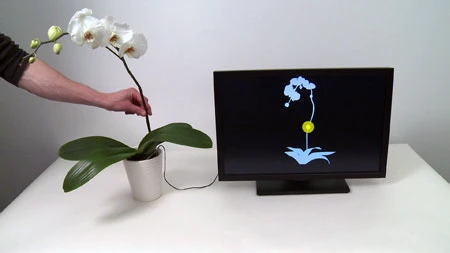
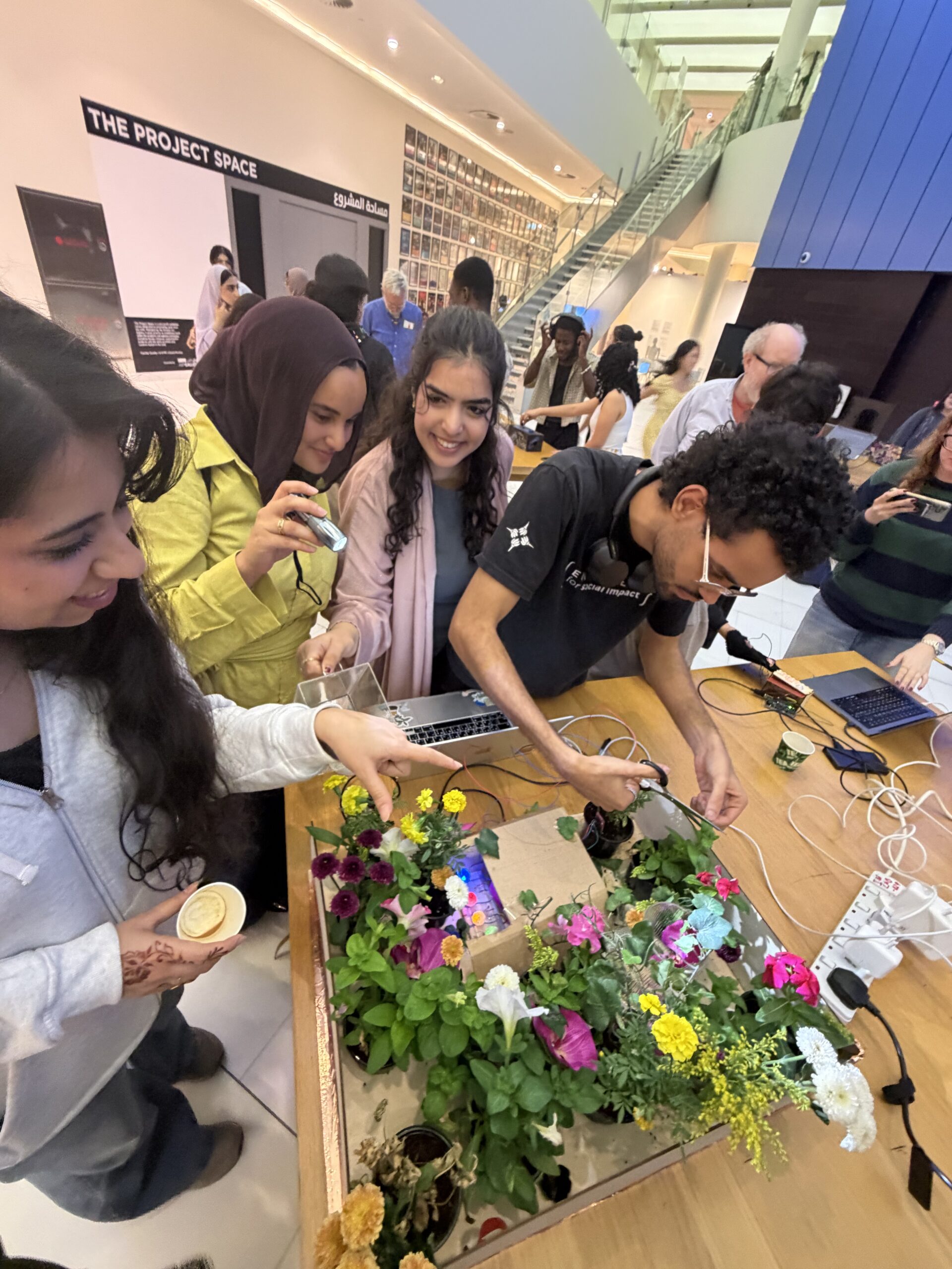
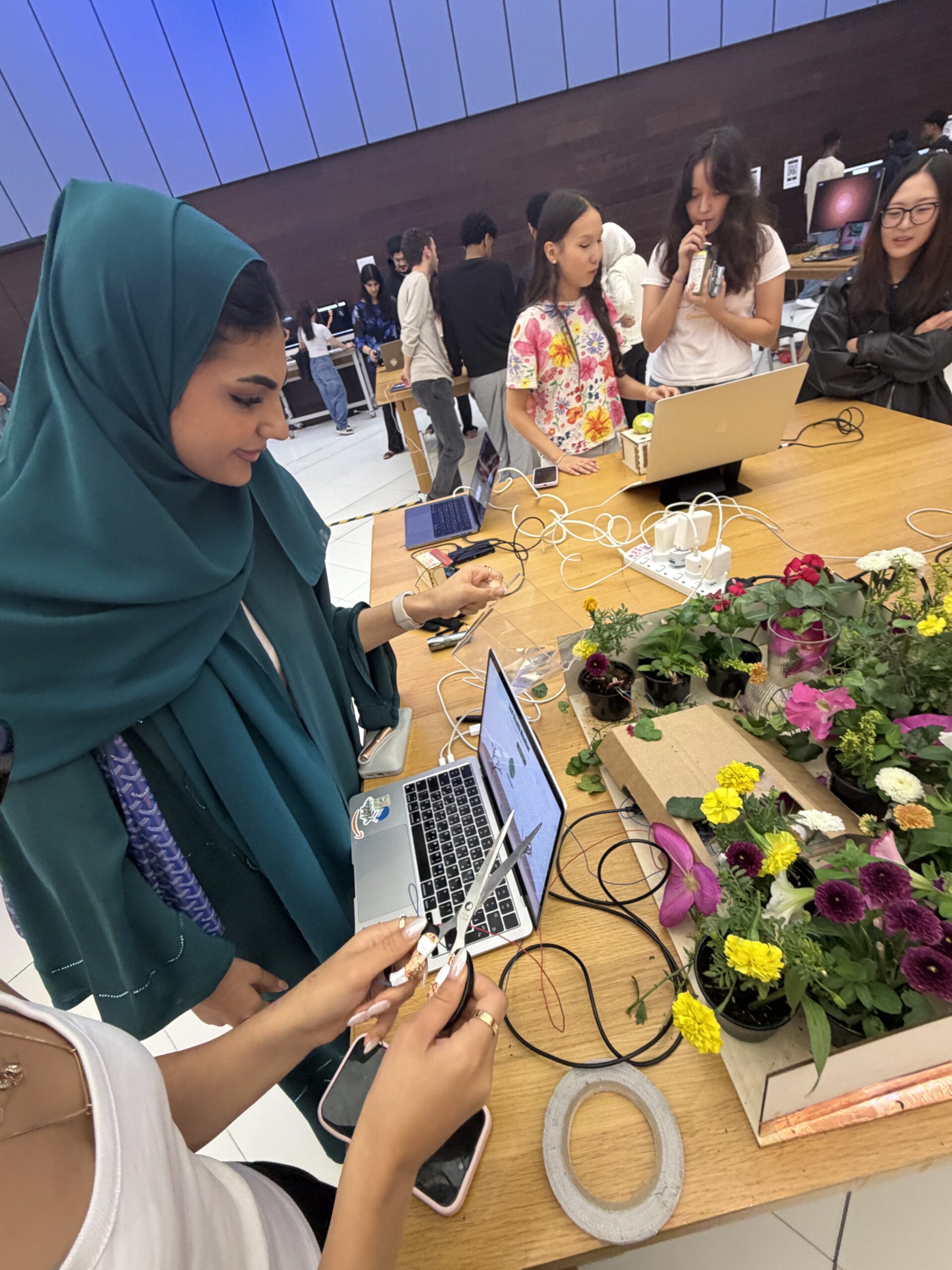
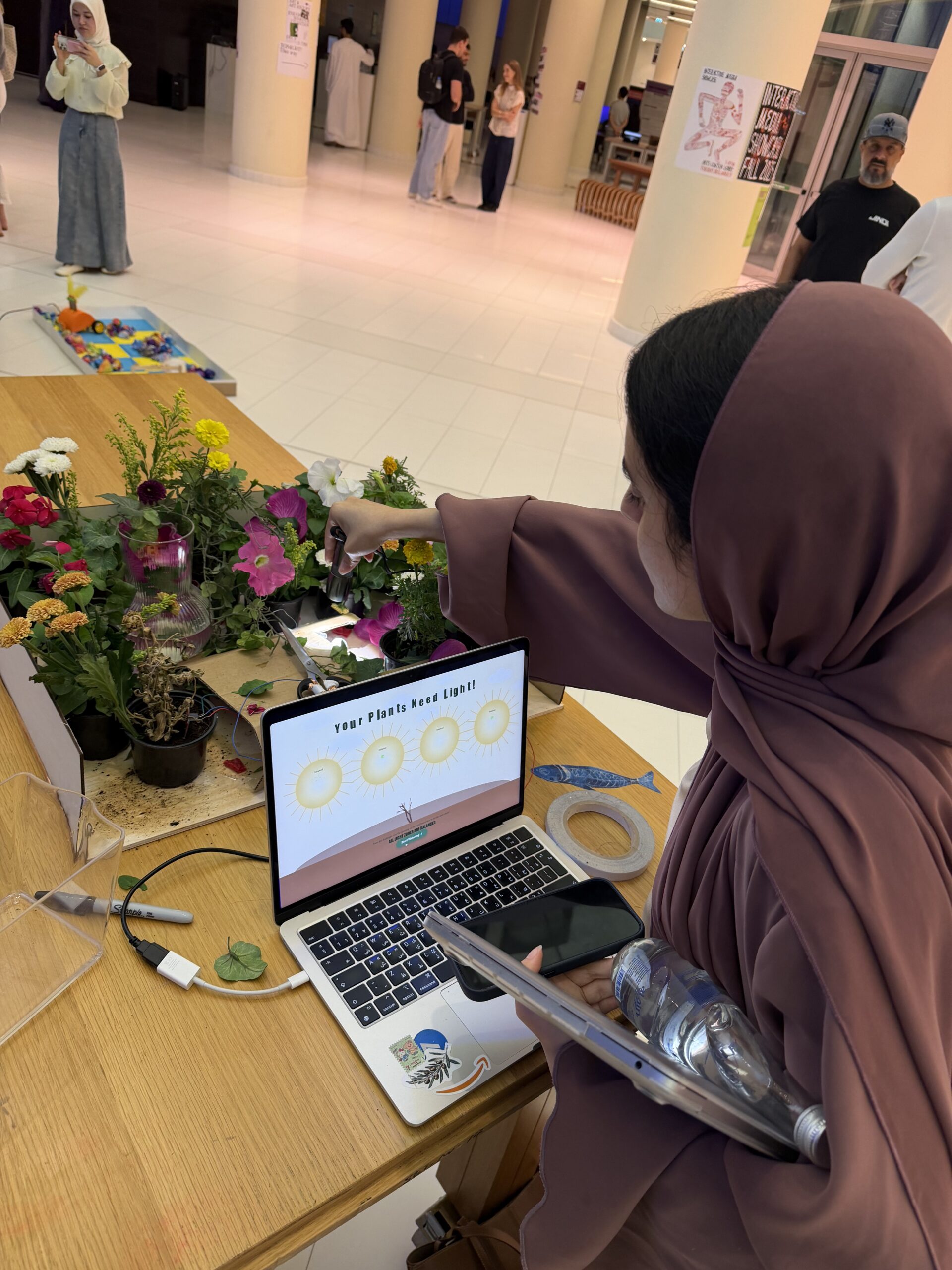
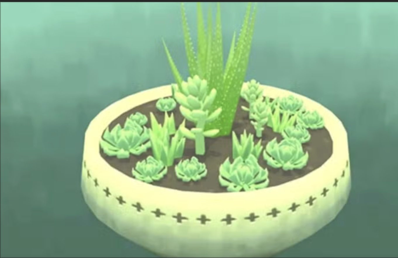
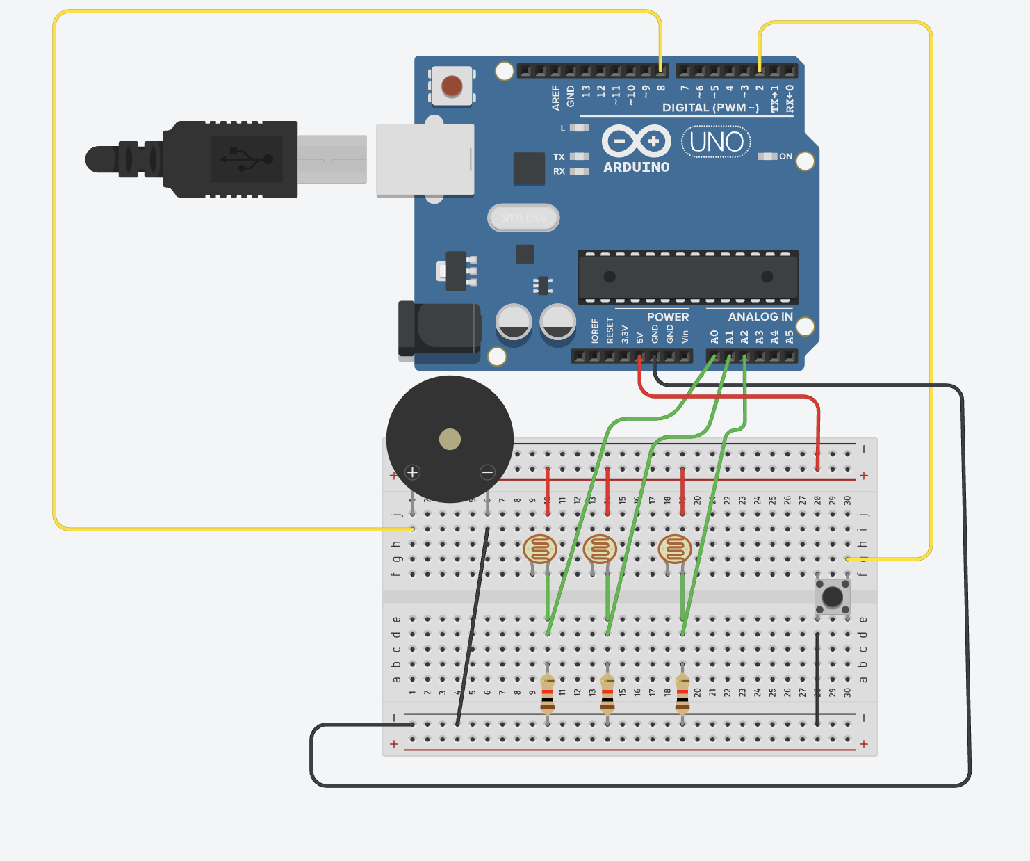
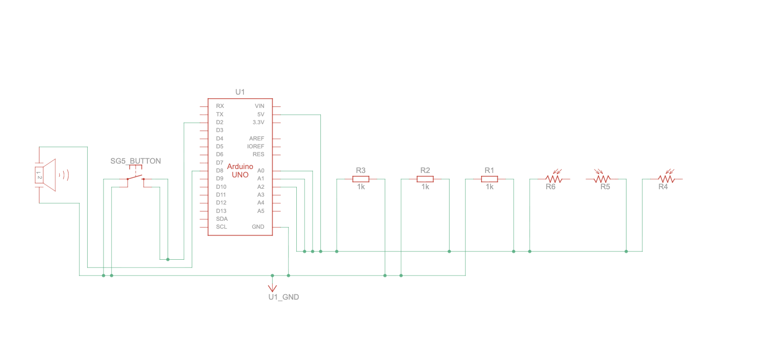
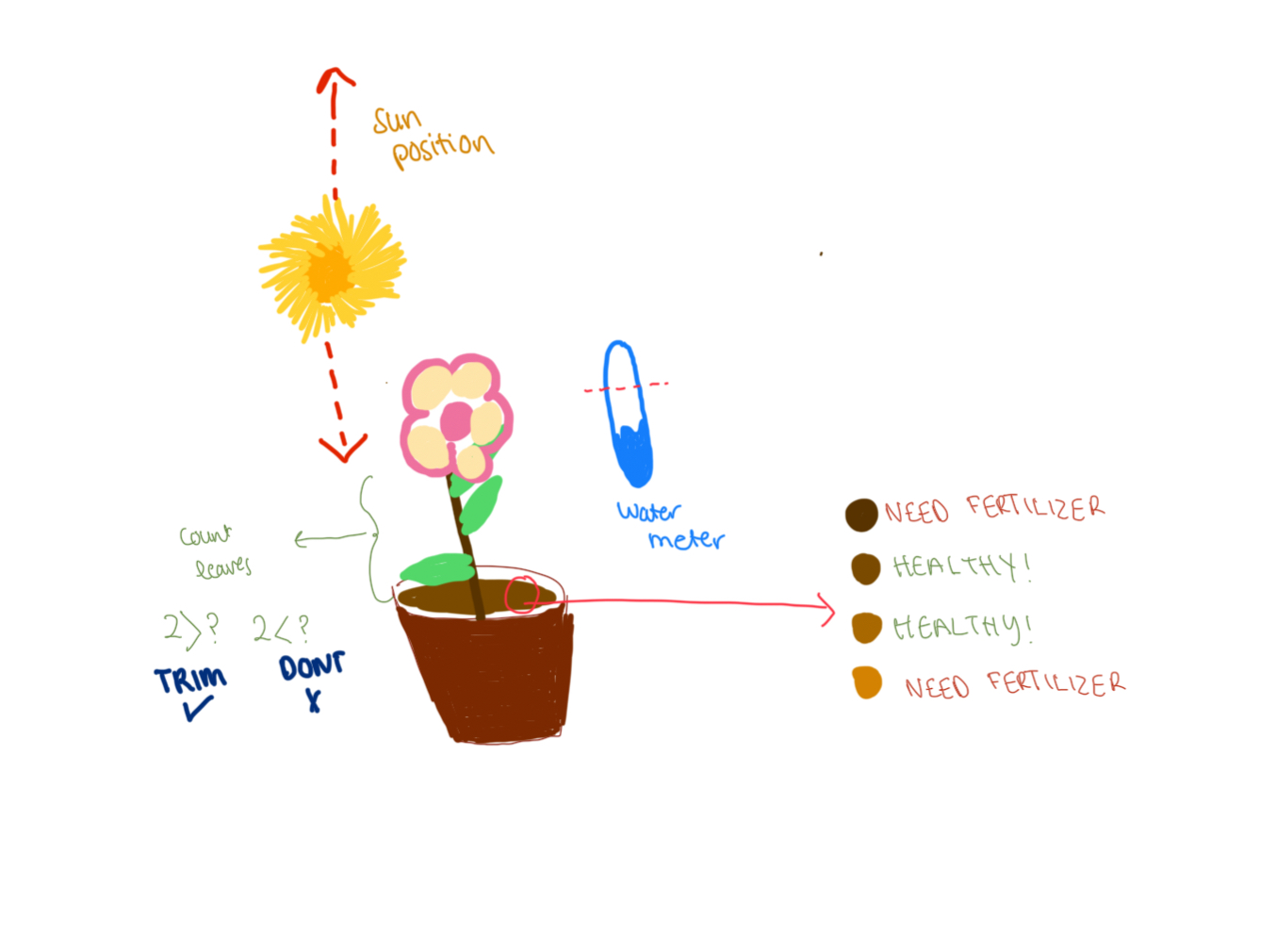
The Plant Care Station, is an interactive experience that allows users to experience the basic steps of caring for a plant using arduino sensors and creative digital feedback through p5. The concept blends physical interaction with a digital narrative. For instance,  users provide sunlight, water, fertilizers and leaf maintenance to a virtual plant by triggering corresponding sensors in the physical setup. Light sensors respond to flashes of brightness, a moisture sensor detects watering actions, and a capacitive sensor tracks leaf trimming. Each successful step of taking care of the plant advances the user through a series of stages, visually reflecting the plant’s growth and wellbeing. The goal of the concept is to make plant care feel engaging, intuitive, and educational by transforming everyday actions into an interactive journey.

Implementation: Interaction Design

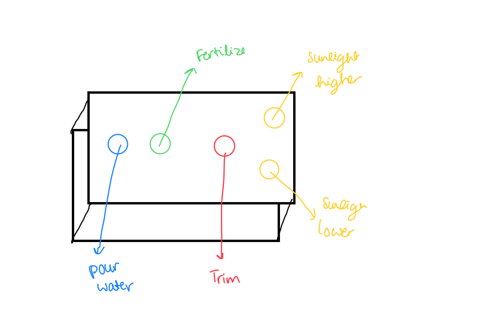
The interaction design of my project mainly involves elements of p5.js that responds directly to sensor input (digital and analog) from the Arduino. Each stage from sunlight, watering, to leaf-trimming has its own visual environment and logic, and the user’s physical actions with the sensors determine how the  the sketch moves forward.

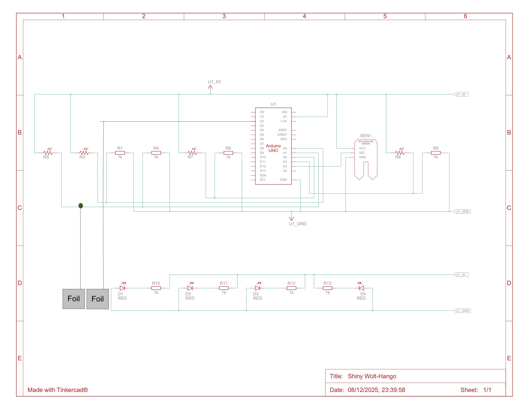
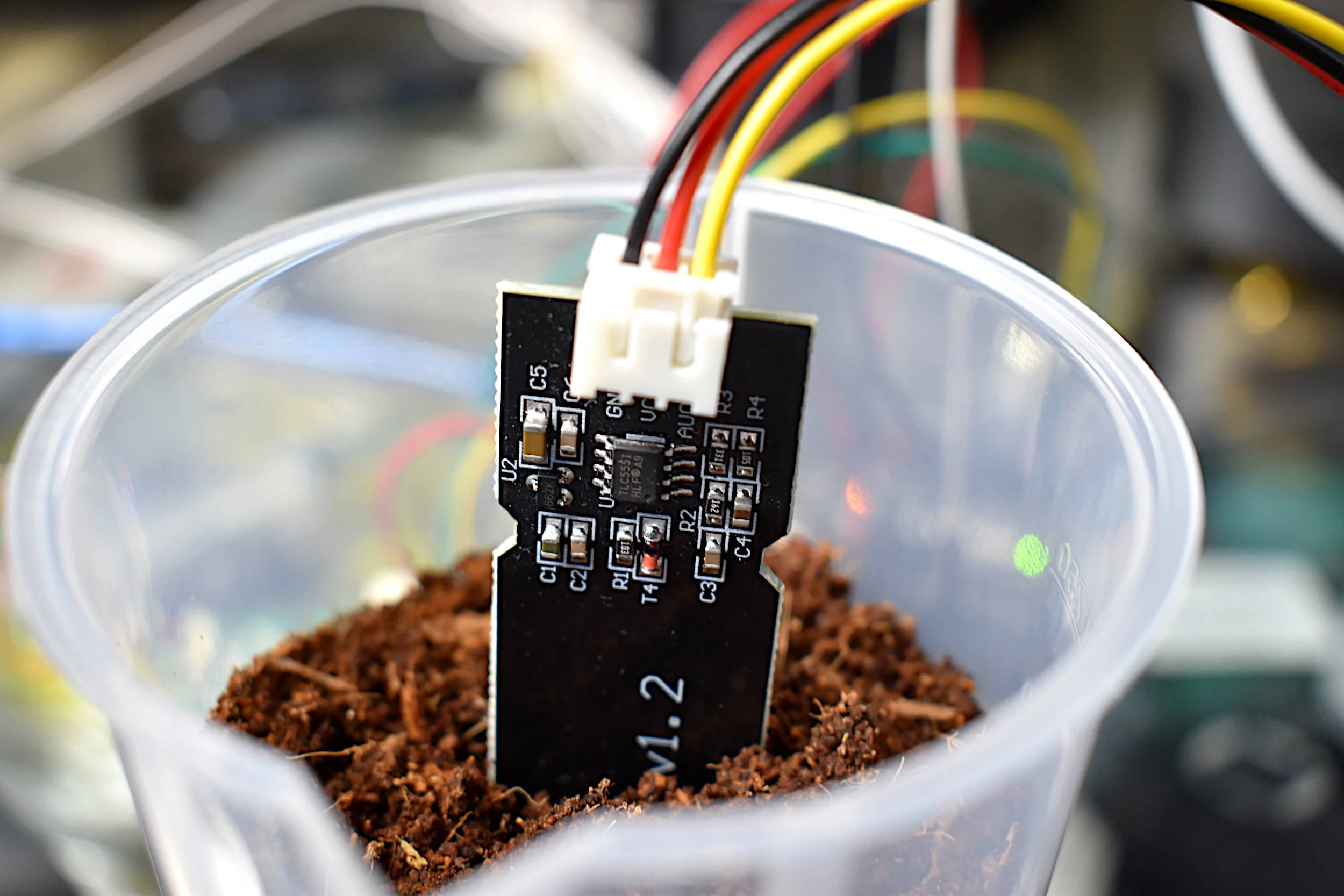
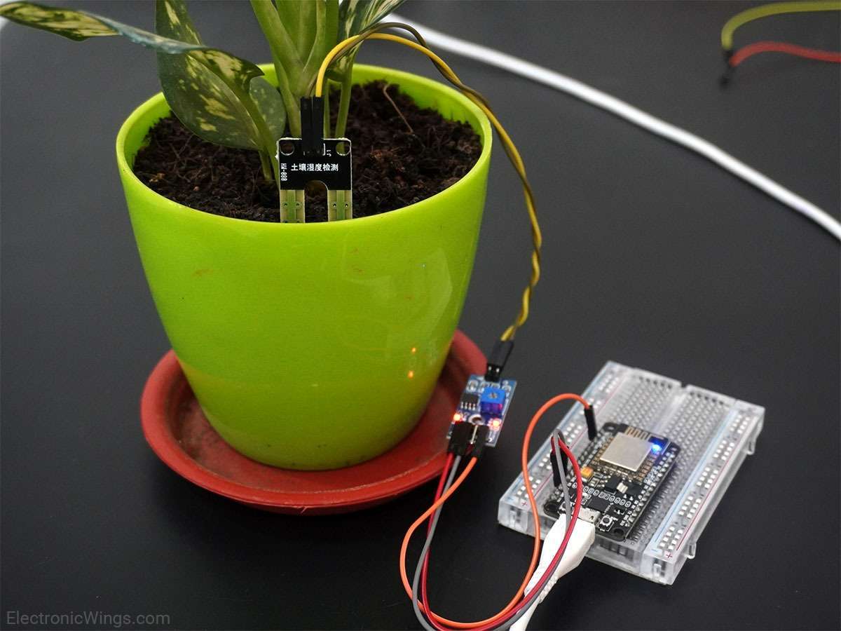
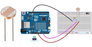
The light sensors trigger progression when the brightness crosses a defined threshold, making the sun figures appear larger and brighter in the p5 program.  The moisture sensor stops updating once the soil reaches the required moisture level, based on our defined threshold that was set during testing.  Lastly, the capacitive sensor on both sides of the scissors detects transitions from “NO_TOUCH” to “TOUCH” to count how many leaves the user has pruned.  This design ensures that the interaction feels responsive and purposeful.


Arduino Code:

#include <CapacitiveSensor.h> // we are using the CapacitiveSensor library so we can use capacitive touch sensing this is measuring changes in capacitance

CapacitiveSensor capSensor = CapacitiveSensor(8, 7); // here we make the cap sensor object whic uses pins 8 and 7 ans the send and recieve pins
const int TOUCH_PIN = 2;// this is the pin which we have the foil touch connected

const int ledPins[4] = {12, 11, 10, 13}; // these are all the pins we have dedictedm for the leds

bool partyMode = false; //party mode is set for the order in which the leds are lit 
int currentLED = 0; //index of the current led starts from 0 ends at 3
int waveDirection = 1;   // wave direction varaible alternates between 1 and -1 for the order in which the leds wave is lit
unsigned long lastUpdate = 0; //stores the last time the leds were updated


const int waveInterval = 30; // adjust to 20 for fast led change


void setup() {
  Serial.begin(9600);  //settung the serial connection at 9600 baud so ard can talk to p5
  pinMode(TOUCH_PIN, INPUT_PULLUP); // this allows for the conductive contact: when touched- reads HIGH when not reads LOW

  for (int i = 0; i < 4; i++) {//looping over all the led light 
    pinMode(ledPins[i], OUTPUT);
    digitalWrite(ledPins[i], LOW); //turn off initialluy
  }
}


void loop() { 

  int soil = analogRead(A4); delay(2); // for the soil moisture senor
  int a0 = analogRead(A0); delay(2); // light sensors 
  int a1 = analogRead(A1); delay(2);//light sensors 
  int a2 = analogRead(A2); delay(2);//light sensors 
  int a3 = analogRead(A3); delay(2);//light sensors 

  long capValue = capSensor.capacitiveSensor(30); //number of samples set to 30, after testing found this was the best value that did not compromise the speed and had good enough accuracy
  bool touched = (digitalRead(TOUCH_PIN) == LOW); //reading of digital pin 2 LOW--> baiscally indicated contact
//send all readings to Serial for p5
  Serial.print(soil); Serial.print(",");
  Serial.print(a0); Serial.print(",");
  Serial.print(a1); Serial.print(",");
  Serial.print(a2); Serial.print(",");
  Serial.print(a3); Serial.print(",");
  Serial.print(capValue); Serial.print(",");
  Serial.println(touched ? "TOUCH" : "NO_TOUCH");


//here we listen for commands from P5
  if (Serial.available()) {
    String cmd = Serial.readStringUntil('\n'); //check for incoming data stop when you find a new line
    cmd.trim();//break there
 
    if (cmd == "LED_ON") { //we send this from p5 when we reached the last page 
      partyMode = true; //turn party mode on for leds
      currentLED = 0;
      waveDirection = 1;// move leds on from left to right
    }
    else if (cmd == "LED_OFF") {
      partyMode = false;//turn party mode off for leds
      for (int i = 0; i < 4; i++) digitalWrite(ledPins[i], LOW);//one by one
    }
  }


if (partyMode) { //light turning on order
    unsigned long now = millis(); 
    const int blinkInterval = 120; // adjust speed here

    if (now - lastUpdate >= blinkInterval) { //checking the time intervals beywen leds lit

        static bool ledsOn = false; //in every blinkInterval we toggle whether leds should be on or of
        ledsOn = !ledsOn;  // toggle on to off

        for (int i = 0; i < 4; i++) {//loops through all 4 LEDs
            digitalWrite(ledPins[i], ledsOn ? HIGH : LOW); //true set high false set low
        }

        lastUpdate = now; //refresh the last updated time fpr the next toggle 
    }
}


  delay(5);
}

Description and Main functionalities: My Arduino program combines multiple sensors (analog and digital) and LED effects to communicate with a p5.js sketch and create interactive plant care visuals. It uses the CapacitiveSensor library to detect touch through changes in capacitance , while a separate foil touch sensor on pin 2 provides a simple digital touch reading. Four LEDs connected to pins 12, 11, 10, and 13 are controlled through a party mode system that makes them blink together when triggered by p5.js. In the main loop, the Arduino continuously reads data from the soil moisture sensor (A4), four light sensors (A0–A3), the capacitive touch sensor, and the foil touch input. All these sensor values are then sent over Serial at 9600 baud to p5.js in a comma-separated format- which was helpful for debugging especially with the soil moisture sensor when the wires would come off. The code also listens for incoming Serial commands from p5, such as our ending LED-ON which activates party mode, causing all LEDs to flash on and off . A small delay at the end stabilizes the sensor readings and controls the noise.
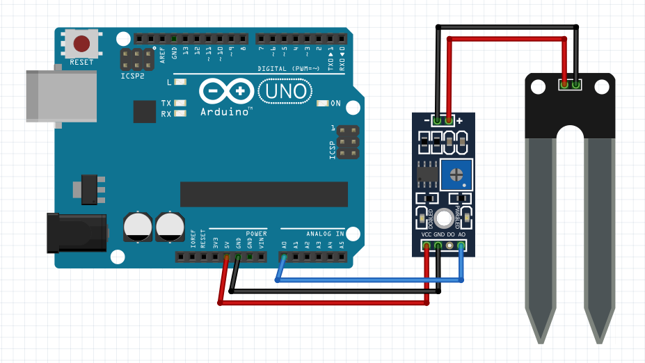
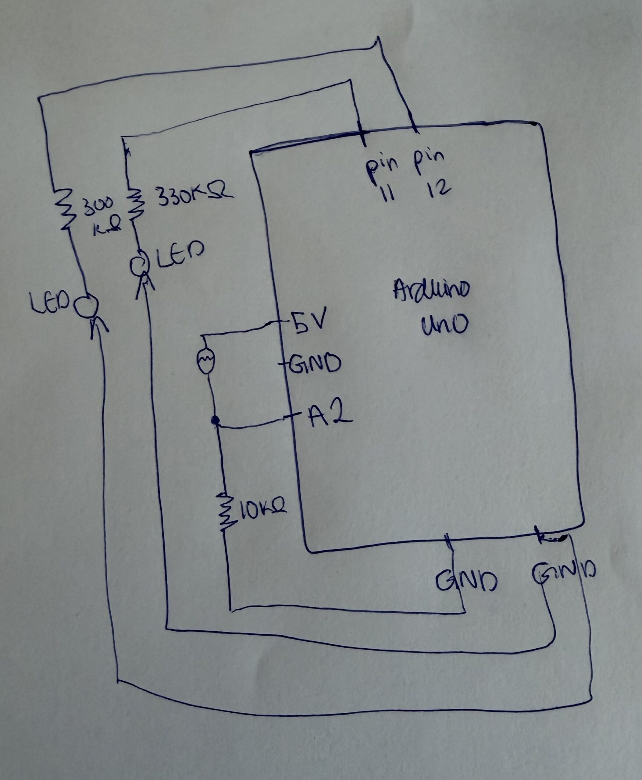
Schematic:

P5 Description:

1. Serial Communication & Sensor Integration

The p5.js sketch’s main logic that makes this game interactive is built around serial communication with the Arduino. The sketch kind of acts as the visual and  interactive front-end for plant-care data. For every frame the program   checks whether the serial port is open, reads a full line of comma-separated values, and parses seven different sensor readings: soil moisture, four light sensors, a capacitive sensor, and the foil touch state. These values drive the logic of each game stage from light balancing to watering and pruning. The code also sends signals back to the Arduino using simple text commands such as “LED_ON”, “LED_OFF” allowing the arduino side(specifically the LED) to respond to the user’s progress. This bidirectional setup makes the interface feel alive, creating a tight feedback loop between the digital visuals and real environmental interactions.

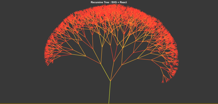
2. Recursive Tree System (Inspired by Decoding Nature Lectures)

A major visual element of my p5 sketch is a dynamic, recursive tree -inspired directly by concepts from the Decoding Nature course lectures. Each game page grows to a more mature tree configuration, by changing trunk thickness, branch angles, branch scaling, blossom density, and root structure. The trees are generated using a recursive branching function that draws a segment, translates upward, and then splits into multiple smaller branches with subtle randomness. The result is a nature-inspired visualization built from mathematical rules, but artistically tuned to feel alive and expressive.

3. Additional Interactive & UI Features

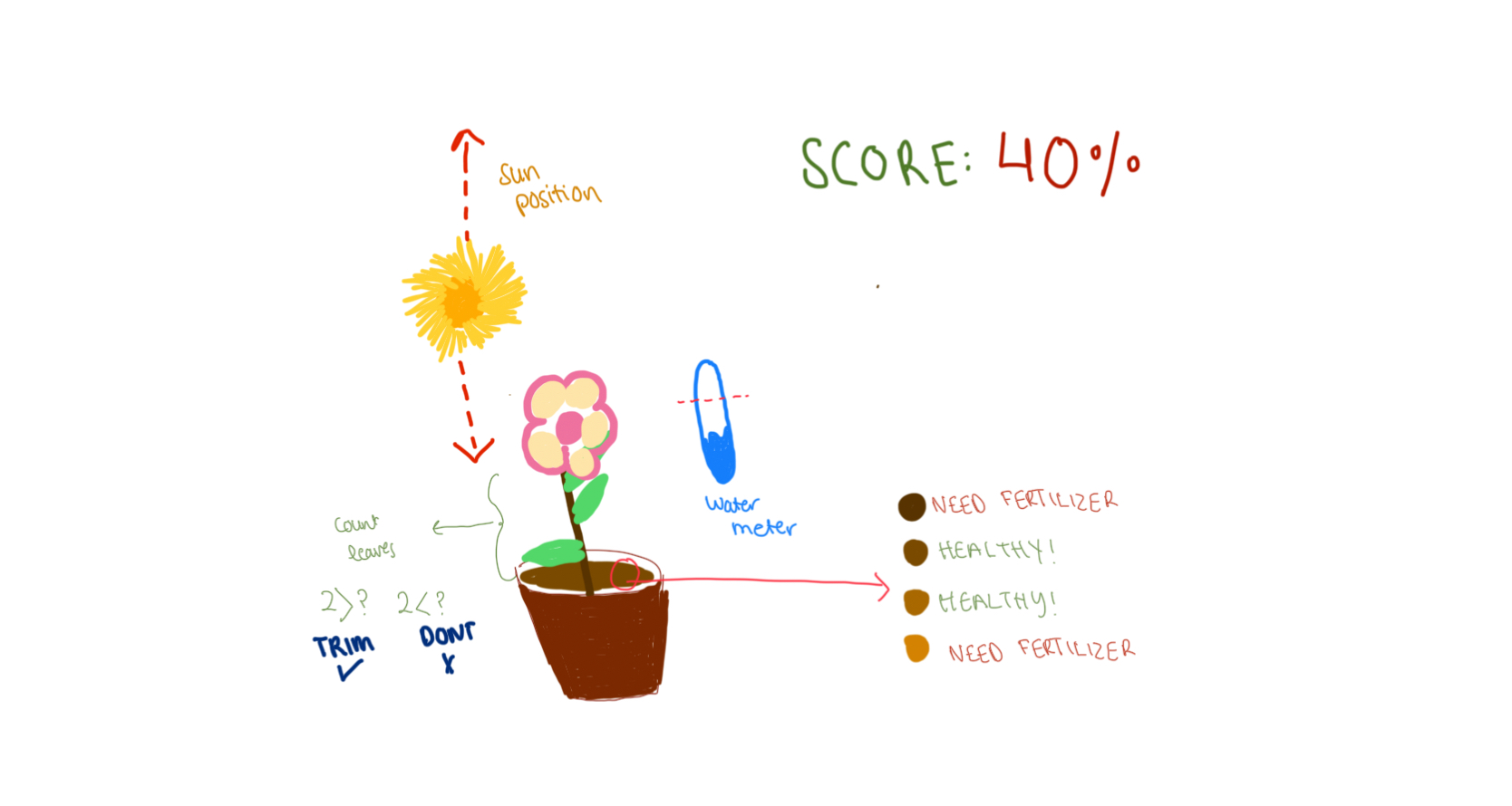
Beyond the analog and digital sensors and trees, the sketch builds a complete game like some functions that make animated text, responsive buttons, confetti celebrations, and stage-based UI transitions. Each page has its own  layout, and unified design for the buttons, and a modern interface with moving characters for the titles. The bouncing text titles adds a playful touch. The sketch also has an input field that allow the user to specify how many leaves they expect to prune- by observing the darker color leaves. Confetti bursts appear when a light sensor zone is completed, rewarding the user visually and allowing them to move to the next round. Throughout the experience, actions like watering, pruning, and finishing a session are tied to both sensor readings and visual transitions, giving users a feeling of caring for a plant step by step, both physically and digitally.

Embedded Sketch:

Communication Between Arduino and P5:

The communication between the Arduino and p5.js begins as soon as the sketch loads. This is when p5 creates a serial port object and tries to open the  port at a baud rate of 9600. Once the port is open, p5 continuously listens for incoming data in the draw loop. The Arduino in return sends a full line of comma-separated sensor values: soil moisture, four light readings, capacitive value, and foil-touch state. This is then read by  p5 using the readuntil where we stop at /n for new lines.  It then updates into its variables each frame. As the user interacts with the interface, p5 interprets these sensor values to move the game logic forward and visuals, such as lighting suns, filling the soil bar, or counting pruning events. Communication also flows in the opposite direction: when the user reaches certain milestones for exaple like completing the session, p5 will send back the commands to Arduino using port.write , such as “LED-ON” and trigger celebratory LED behavior. This back-and-forth loop of sending sensor data from Arduino and sending commands from p5 creates a synchronized, interactive experience tightly linking physical actions with digital responses.

Parts I am Particularly Proud of:

At the start of the project, I had no experience working with sensors like the  the soil moisture sensor, so even understanding their raw readings felt overwhelming. I didn’t know how to interpret the values, how to calibrate them, or how to integrate them into meaningful interactions. Through tutorials, schematics, documentation, and simple testing sketches, I gradually learned how each sensor behaved and what its data actually meant. This process helped me understand how to map their values into thresholds, smooth out noise, and ultimately use them confidently within my project.

I am also particularly proud of the physical design work . Using the laser cutter, I built a wooden enclosure for the plants and the tools(scissors, water and flash light). This was my first time designing designing something like this, and learning how to convert a digital sketch into precise vector cuts was incredibly rewarding. In addition, I used Tinkercad and the 3D printer to design small globe pieces that sit over the LEDs and act as tiny diffusers, creating a fun disco-style glowing effect during the celebration mode. These handmade physical elements added personality to the project and made the final interaction feel more polished and playful.

Struggles:

One major challenge was scaling the interaction by switching from an Arduino Uno to an Arduino Mega so I could add more sensors, such as piezo inputs, but the process was difficult, and I accidentally burned the Mega while troubleshooting wiring. Another struggle came from the fabrication side: when designing LED covers, the 3D printer malfunctioned and could only produce partial hemispheres instead of full spheres, which limited the effect I originally envisioned. These setbacks were frustrating in the moment, but they pushed me to adapt quickly, rethink my design choices, and find creative workarounds.

Areas of Future Improvement:

In the future, I would love to expand the project by integrating different, more advanced sensors that could make the plant-care experience even more immersive. Adding sensors like temperature probes, humidity sensors, airflow detectors, or even distance/gesture sensors could enrich the interaction and make the plant feel more “alive.” For example, a temperature sensor could simulate climate effects, a humidity sensor could influence plant hydration, or an ultrasonic sensor could let users wave their hands to create virtual wind. Exploring these cooler sensors would open up new possibilities for storytelling, responsiveness, and deeper environmental simulation within the project.


I also used AI (ChatGPT) in two key ways: first, to refine the visual design of the interface by helping me choose cohesive color schemes and polished button styling; and second, to analyze batches of raw sensor readings from the serial monitor so I could determine reliable thresholds for light, moisture, and touch detection. These tools and references collectively helped shape the final project, balancing hands-on experimentation with guided learning.

Here’s an example of what those blocks of code look like:

function styleLeafInput(inp) {
  inp.style("padding", "10px 14px"); // inner spacing for comfortable typing (chatgpt design choice)
  inp.style("font-size", "18px"); // readable font size
  inp.style("border-radius", "999px"); // pill-shaped rounded input (chatgpt styling suggestion)
  inp.style("border", "2px solid " + COLOR_ACCENT_SOFT); // soft accent border for aesthetic consistency
  inp.style("outline", "none"); // removes default browser outline
  inp.style("font-family", "Poppins, Arial, sans-serif"); // clean modern font (chatgpt ui recommendation)
  inp.style("box-shadow", "0 3px 10px rgba(136, 182, 155, 0.35)"); // subtle shadow for depth (chatgpt design touch)
  inp.style("background-color", "#FFFFFF"); // white background for high readability
  inp.style("color", COLOR_TEXT_DARK); // dark text for good contrast
}


Or such as these color schemes:

 stroke("#6B5032");
drawingContext.shadowColor = "rgba(245, 210, 110, 0.8)";


Showcase:

Week 13- User Testing

Are they able to figure it out? Where do they get confused and why? Do they understand the mapping between the controls and what happens in the experience?

The one thing I did not make very clear is where they should point the light to, which are the light sensors. I think testing this with people that have done IM classes before was not suitable because they knew how each sesnor looked like therefor knew how to trigger them. So the light sensors and water sensors should be intergrated in a way that allows the user to understand what they should do to trigger the sensor.

  • What parts of the experience are working well? What areas could be improved?

I think the overall functionalities of the sensors work well, and the thresholds are defined well. I want to make all the wires connected to the Arduino and bread board sit more neatly because they do get tangled at time. I also want to make sure that the the wooden case around my project has a small hole or opening to let the connection from the laptop to the Arduino.

  • What parts of your project did you feel the need to explain? How could you make these areas more clear to someone that is experiencing your project for the first time?

One part of my project that I needed to explain more clearly was how users should interact with the sensors—specifically, where to point the light for the light sensors and how to activate the water sensor. Because many of the people I tested with had prior IM experience, they already recognized what the sensors looked like and intuitively knew how to trigger them, which made it harder for me to notice confusion. For a first-time user, however, the mapping between their actions and the project’s responses is not immediately obvious. In future iterations, I want to better integrate or label the sensors so that users can naturally understand where to shine the light or where to place the water without requiring external explanation.

DEMO of User Testing:

IMG_8795


Week 12- Final Project Proposal

Finalised Concept for the Project

Plant Care Station is an interactive, game-like system that combines physical sensors through Arduino with a browser-based visual interface through p5.js.
The project teaches users about plant care (light, water, soil, and touch) through playful interactions, animations, glowing suns, and confetti celebrations.

My project uses sensor data from the Arduino : including four light sensors,  capacitive touch sensors using foil, and a soil moisture sensor — which are visualized in p5.js as a growing, living plant environment. As the user helps the plant receive enough light, fertilizer and moisture, the interface responds through movement, glowing suns, page transitions, and celebratory effects.

Arduino to P5:

  • 4 Light Sensors: Once the light has hit the sensors at a specific threshold, we use the p5 interface to show the user which sensors need more light. Once the light threshold is met, then confetti is thrown and the user can move to the next page.
  • Capacitative Touch sensors: I used aluminium foil to act as a capacitative touch sensor. This foil will be stuck to the scissors so that everytime the reading goes from NO-CONTACT to CONTACT: I count that as one leaf cut.
  • Capacitative Touch sensors/Pressure sensors: Once the fertilizer is paced in the soil we confirm that on the p5 screen and allow the user to move to the next page
  • Soil Moisture Sensor: Once the plant is watered to a specific threshold we notify the user on the p5 screen

 P5 to Arduino:

  • Once all the Steps are complete, p5 will send a signal to Arduino and the colourful LEDs will start flashing- to celebrate the completion.


Final Project Proposal: Plant Care Station

Final Project Proposal: Plant Care Station

The final project idea I have in mind is to make a connection between the Arduino and p5.js to take care of plants. Through buttons the user can fill the meter for water (through a blue buttons), then add fertilizer (yellow button), to trim (red button), to move sunlight closeness(yellow buttons one for arrow up one for arrow down).

You can even get a score or a rating based on how well you took care of the plant. Checking each metric. The Arduino part would be multiple buttons and a box that covers these buttons with larger buttons on the wooden box (design is inspired by the beat hoven project displayed in class).

ARDUINO

p5

Week 12: Serial Communication

For this week’s assignment, Zeina and I worked on three different exercises that focused on serial communication.

NOTE: We mostly used the exact copy of the arduino and p5 that was demoed in class with just an addition of 2-3 lines for each program. For these 2-3 lines we added comments, and for the rest of the lines we kept the same comments already included by the code

1- Make something that uses only one sensor  on Arduino and makes the ellipse in p5 move on the horizontal axis, in the middle of the screen, and nothing on arduino is controlled by p5

ARDUINO CODE

void setup() {
  Serial.begin(9600);
}

void loop() {
  int sensorValue = analogRead(A1); // 0–1023
  Serial.println(sensorValue);             // send to p5.js
  delay(50);
}

P5 CODE

let port;
let connectBtn;
let baudrate = 9600;
let lastMessage = "";
let sensorValue = 0;

function setup() {
  createCanvas(400, 400);
  background(220);

  //Setting the global variable port to a new serial port instance inside setup:
  port = createSerial();

  // we can open ports we have used previously without user interaction
  let usedPorts = usedSerialPorts(); //array of used ports
  if (usedPorts.length > 0) {  
    port.open(usedPorts[0], baudrate); //if any used port is in the array, open that port with 9600 baudrate
  }

  // any other ports (new ones) can be opened via a dialog after user interaction (see connectBtnClick below)
  connectBtn = createButton("Connect to Arduino");
  connectBtn.position(width/2, 270);
  connectBtn.mousePressed(connectBtnClick);

}

function draw() {
  background("white");
 
  // Read from the serial port. This is a non-blocking function. If a full line has come in (ending in \n), it returns that text. If the full line is not yet complete, it returns an empty string "" instead.
  let str = port.readUntil("\n");
  if (str.length > 0) {   // if str -a string- has any characters
    // print(str);
    lastMessage = str;
    sensorValue = int(lastMessage);  
  }
 
  //draw ellipse mapped to horizontal axis
  let x = map(sensorValue, 0, 1023, 0, width);  
  ellipse(x, height / 2, 40, 40);
 
  // Display the most recent message
  text("Last message: " + lastMessage, 10, height - 20);

  // change button label based on connection status
  if (!port.opened()) {
    connectBtn.html("Connect to Arduino");
  } else {
    connectBtn.html("Disconnect");
  }
}

function connectBtnClick() {
  if (!port.opened()) {
    port.open("Arduino", baudrate);
  } else {
    port.close();
  }
}


2-Make something that controls the LED brightness from p5

DEMO

IMG_8392 (2)

ARDUINO CODE

// Week 12 Example of bidirectional serial communication

int leftLedPin = 2;
int rightLedPin = 5;

void setup() {
  Serial.begin(9600);

  pinMode(LED_BUILTIN, OUTPUT);
  pinMode(leftLedPin, OUTPUT);
  pinMode(rightLedPin, OUTPUT);

  digitalWrite(leftLedPin, HIGH);
  digitalWrite(rightLedPin, HIGH);
  delay(200);
  digitalWrite(leftLedPin, LOW);
  digitalWrite(rightLedPin, LOW);

  while (Serial.available() <= 0) {
    digitalWrite(LED_BUILTIN, HIGH);
    Serial.println("0,0");
    delay(300);
    digitalWrite(LED_BUILTIN, LOW);
    delay(50);
  }
}

void loop() {
  while (Serial.available()) {
    digitalWrite(LED_BUILTIN, HIGH);

    int left = Serial.parseInt();
    int right = Serial.parseInt();

    if (Serial.read() == '\n') {

      // -----------------------
      // ONLY CHANGE IS HERE:
      // -----------------------
      digitalWrite(leftLedPin, left);     // left stays ON/OFF
      analogWrite(rightLedPin, right);    // right is now BRIGHTNESS (0–255)
      // -----------------------

      int sensor = analogRead(A0);
      delay(5);
      int sensor2 = analogRead(A1);
      delay(5);
      Serial.print(sensor);
      Serial.print(',');
      Serial.println(sensor2);
    }
  }
  digitalWrite(LED_BUILTIN, LOW);
}

p5 CODE

let port; // making a var to hold the serial port
let baudrate = 9600; // speed for talking to arduino
let brightnessSlider; // slider to pick brightness
let smoothBrightness = 0; //transition into the brightness instead of jumping

function setup() {
  createCanvas(400, 200); // just making a small canvas for ui 
  textSize(18); // bigger test

  brightnessSlider = createSlider(0, 255, 0); // slider from 0 to full bright
  brightnessSlider.position(20, 80); // where it shows up on screen
  brightnessSlider.style('width', '200px'); // make it a bit wider

  port = createSerial(); // create a serial object so we can connect to arduino

  let used = usedSerialPorts(); // check if we already used a port before
  if (used.length > 0) {
    port.open(used[0], baudrate); // auto connect to the last used port
  }
}

function setupSerial() {
  if (!port.opened()) { // if no connection yet
    port.open("Arduino", baudrate); // try to open one 
  } else {
    port.close(); // if already open then close it (toggle)
  }
}

function draw() {
  background(240); // light grey 

  if (!port.opened()) {
    text("Press SPACE to connect", 20, 30); // tell the user what to do
  } else {
    text("Connected!", 20, 30); // connection message
  }

  let target = brightnessSlider.value(); // get the slider value

  // do transitional brightness
  smoothBrightness = lerp(smoothBrightness, target, 0.07);
 

  text("Brightness: " + int(smoothBrightness), 20, 70); // show the number

  // actually send the brightness to the arduino
  if (port.opened()) {
    let sendString = "0," + int(smoothBrightness) + "\n"; // left=0 right=smooth
    port.write(sendString); // send it over serial
  }
}

function keyPressed() {
  if (key === " ") {
    setupSerial(); // hitting space toggles the port connection
  }
}

3-Take the gravity wind example (https://editor.p5js.org/aaronsherwood/sketches/I7iQrNCul) and make it so every time the ball bounces one led lights up and then turns off, and you can control the wind from one analog sensor

ARDUINO CODE

void setup() {
  pinMode(2, OUTPUT);
  Serial.begin(9600);
}

void loop() {
  int sensorValue = analogRead(A1);
  Serial.println(sensorValue);

  //check for bounce 
  if (Serial.available() > 0) {
    //if 1, light up led
    if (Serial.parseInt() == 1) {             
      digitalWrite(2, HIGH);
      delay(100);                          
      digitalWrite(2, LOW);
    }
  }
  delay(10);
}

P5.JS CODE

let velocity;
let gravity;
let position;
let acceleration;
let wind;
let drag = 0.99;
let mass = 50;
let port;
let connectBtn;
let baudrate = 9600;
let lastMessage = "";
let sensorValue = 0;

function setup() {
  createCanvas(640, 360);
  noFill();
  position = createVector(width / 2, 0);
  velocity = createVector(0, 0);
  acceleration = createVector(0, 0);
  gravity = createVector(0, 0.5 * mass);
  wind = createVector(0, 0);

  //Setting the global variable port to a new serial port instance inside setup:
  port = createSerial();

 
  // we can open ports we have used previously without user interaction
  let usedPorts = usedSerialPorts(); //array of used ports
  if (usedPorts.length > 0) {  
    port.open(usedPorts[0], baudrate); //if any used port is in the array, open that port with 9600 baudrate
  }
// any other ports (new ones) can be opened via a dialog after user interaction (see connectBtnClick below)
  connectBtn = createButton("Connect to Arduino");
  connectBtn.position(width/2, 270);
  connectBtn.mousePressed(connectBtnClick);
}

function draw() {
  background(255);
 
  // Read from the serial port. This is a non-blocking function. If a full line has come in (ending in \n), it returns that text. If the full line is not yet complete, it returns an empty string "" instead.
  let str = port.readUntil("\n");
  if (str.length > 0) {   // if str -a string- has any characters
    // print(str);
    lastMessage = str.trim();
    sensorValue = int(lastMessage);    
  }
 

  //wind controlled by analog sensor
  wind.x = map(sensorValue, 0, 1023, -1, 1);
  console.log("Sensor value: " + sensorValue);
 

  applyForce(wind);
  applyForce(gravity);

  velocity.add(acceleration);
  velocity.mult(drag);
  position.add(velocity);
  acceleration.mult(0);

  ellipse(position.x, position.y, mass, mass);

  // Bounce detection
  if (position.y > height - mass / 2) {
    velocity.y *= -0.9; // Dampening
    position.y = height - mass / 2;

    //send bounce signal to Arduino
    port.write("1\n");
  }
// Display the most recent message
  text("Last message: " + lastMessage, 10, height - 20);

  // change button label based on connection status
  if (!port.opened()) {
    connectBtn.html("Connect to Arduino");
  } else {
    connectBtn.html("Disconnect");
  }
}

function applyForce(force){
  // Newton's 2nd law: F = M * A
  // or A = F / M
  let f = p5.Vector.div(force, mass);
  acceleration.add(f);
}

function keyPressed(){
  if (keyCode==LEFT_ARROW){
    wind.x=-1;
  }
  if (keyCode==RIGHT_ARROW){
    wind.x=1;
  }
  if (key==' '){
    mass=random(15,80);
    position.y=-mass;
    velocity.mult(0);
  }
}

function connectBtnClick() {
  if (!port.opened()) {
    port.openDialog(); // user selects port
  } else {
    port.close();
  }
}

For this week’s reading assignment :

This reading made me really rethink the relationship between disability, design, and visibility. The author’s point about discretion was especially interesting, for example, how so many medical devices are intentionally designed to disappear, as if invisibility equals good design. But the reading also made me question what that invisibility actually communicates. If a product is meant to blend into the skin or look like it’s barely there, does that subtly imply that disability should be hidden? What is the further message?

The contrast with fashion added another interesting layer in my opinion. Fashion openly accepts the idea of being seen, of expressing identity, which is almost the opposite of traditional medical design. I liked the example of eyewear, which shows that a product can address a disability without carrying social stigma, and also can become something expressive and desirable. That overlap suggests disability-related products don’t need to be trapped between being “invisible” or “medical-looking,” and that they can have personality without becoming sensationalized.


Week 10 Sound, Servo motor, Mapping

Inspiration:

For this week’s project, the main inspo for our instrument was Stormae’s Song “Alors on Danse”. We were mainly inspired by the way that the songs main notes are split into 3 notes of varying pitches, with one sound constantly playing in the background. For that reason we varied the pitches of the three sounds our project produces with a 4th note that is constantly playing when the button is pressed.

Concept:

For this week’s project, we used 3 light sensors to play sounds on the piezo speaker, with one note being played constantly when a button is clicked. With the light sensor, once the user’s finger covers the sensor that is when the note is played. Furthermore, we have three sensors each of which plays a different pitch on the piezo speaker. The condition that allows for this is the reading of the sensor in comparison to the threshold we defined. An additional component we added was the button that allows for the sounds to be played on the piezo speaker and then stopped once the button is pressed again.

Code:

int photoPins[3] = {A0, A1, A2};// first we define a list of integers holding the analog pins
int buttonPin = 2; // digi pin 2 for the buttons
int piezzoPin = 8; //digi pin 8 for the piezzo speaker 

int threshold = 700; //this is the threshold fo rte light/no light intensity that worked wit our light sensors in our environment/lighting

bool prevPhoto[3] = {false, false, false}; //keeping track of whether the light sebsir was interacted with or not false initially 
bool prevButton = false; //initially false
bool buttonState = false;//initially false

void setup() {
  pinMode(buttonPin, INPUT_PULLUP); //for the button pint as an input for the arduino
  pinMode(piezzoPin, OUTPUT); //setting the buzzor pin as output so the arduino sneds the sound signal 
  Serial.begin(9600); // serial monitor for debugging
}

void loop() {
  for (int i = 0; i < 3; i++) { //looping over the 3 sensors to reasd their analog value
    int value = analogRead(photoPins[i]); 
    bool tapped = value < threshold; //comparing the value captured by the sensor and the defined threshold
    if (tapped && !prevPhoto[i]) { //checking for tap in the current state compared to prev
      if (i == 0) tone(piezzoPin, 440, 200); // translates to A0
      if (i == 1) tone(piezzoPin, 523, 200); // translates to A1
      if (i == 2) tone(piezzoPin, 659, 200); // translates to A2
    }
    prevPhoto[i] = tapped; //MAKING SURE TO NOTE it as tapped to have a singular tap rather than looping

    Serial.print(value); //serial print
    Serial.print(",");
  }

  bool pressed = digitalRead(buttonPin) == LOW; //setting the reading of the button to low meaning the button is pressed
  if (pressed && !prevButton) { //when the button is pressed state changes from not pressed(false) to presssed(true)
    buttonState = !buttonState;
    if (buttonState) tone(piezzoPin, 784);// if toggled on play a continuoue G5 tone
    else noTone(piezzoPin); //otherwise stop the buzzer
  }
  prevButton = pressed; 

  Serial.println(pressed ? "1" : "0"); //for monitoring purposes

  delay(50);//short delay 
}

Disclaimer: Some AI/ChatGPT was used to help with debugging and allowing multiple elements to work cohesively.

More Specifically:

1- When trying to debug and understand why the button was not working, we used chatGPT’s recommendation to have a statement check if button is pressed is true on the serial monitor (this line: Serial.println(pressed ? “1” : “0”); //for monitoring purposes)
2- Recommended values for frequency in hertz to mimic Alors on Danse (if (i == 0) tone(piezzoPin, 440, 200); // translates to A0 if (i == 1) tone(piezzoPin, 523, 200); // translates to A1 if (i == 2) tone(piezzoPin, 659, 200); // translates to A2) The SECOND parameter

Schematic:

Demo:

IMG_8360

Future Improvements:

As for the future improvements, one main thing we wanted to capture in this project is being to overlap the sounds, but since we were working with one piezo speaker, we were not able to do that. To address this we aim to learn more about how we can maybe start playing the sounds from our laptops instead of the physical speaker we connect to the Arduino. Other improvements could be exploring how we can incorporate different instrument sounds maybe and create an orchestra like instrument.


Reading Reflection:

Reading A Brief Rant on the Future of Interaction Design really made me rethink how we use technology and what we’ve lost in the process. The author points out that what we often label as “futuristic” design like touchscreens and flat device isn’t really that visionary or futurisitc. It’s actually very far from how we connect with the world. When he describes our current technology as “Pictures Under Glass,” it clicked for me how minimal that kind of interaction feels. We’re constantly sliding our fingers across flat screens, but we’ve given up the physical feedback that makes using our hands so intuitive and satisfying. I never thought about how much information we get through touch until he brought up examples like turning the pages of a book or feeling the weight of a glass of water.

What stood out most to me is his idea that our hands and really, our whole bodies are tools for understanding and shaping the world. Technology should amplify that, not suppress it. I realized how much design today caters to convenience and simplicity, but in doing so, it often strips away depth and engagement. His point about how touchscreens make us “finger-blind” hit hard—it’s true that we spend so much time tapping and swiping that we forget what it feels like to truly handle something.

Arduino: analog input & output- Elyazia Abbas

Concept:

For this week’s assignment, I made the Plant Care Assistant. It helps users monitor their plant’s water needs through simple visual feedback. A green LED will light up when the sun exposure is high(simulate with flashlight from phone). A red LED will ligzht up when the sun exposure is low(simulate with moving away flashlight from phone). When users click the yellow button, if it flashes yellow, then the plant is in good state and if it does not flash at all, the plant needs to be taken care of.

Code:

int ledFlashOn = 11;   // led on pin 11 flashes if the plant has enough sunlight
int ledFlashOff = 12;  // led on pin 12  flash red if the plant doesn has enough sunlight
int sensorPin = A2; //sensor pin for the light sensor 

void setup() {
  Serial.begin(9600);
  pinMode(ledFlashOn, OUTPUT);
  pinMode(ledFlashOff, OUTPUT);
}

void loop() {
  int sensorValue = analogRead(sensorPin); //gettign the value of the pin 
  Serial.println(sensorValue); //printing t in the serial monitor

  if (sensorValue > 950) { //if sensor value is greater than 950 
    digitalWrite(ledFlashOn, HIGH); //light up green dont light up red
    digitalWrite(ledFlashOff, LOW);
  } else {
//light up red dont light up green   
    digitalWrite(ledFlashOff, HIGH);
  }

  delay(50); // small delay for stability
}

In my Arduino code we continuously read analog values from a light sensor connected to pin A2, where higher values indicate more light. When the sensor reading exceeds 950 (bright sunlight), the code turns on the green LED on pin 11 while keeping the red LED on pin 12 off, signaling that the plant is receiving adequate sunlight. If the reading falls below 950, it switches to illuminate the red LED while turning off the green one, warning that the plant needs more light. The serial monitor displays real-time sensor readings for debugging, and a 50ms delay ensures stable readings without flickering.

DEMO:

IMG_8353

Hand-Drawn Schematic:

Reflections & Future Improvements:

For future improvements, I’d like to add PWM control to make the LEDs fade in and out for smoother transitions between states, and implement multiple thresholds to show “perfect,” “okay,” and “needs more light” zones instead of just binary feedback. Adding a data logging feature to track light exposure over time would help understand the plant’s daily light patterns.

Reading Reflection:

One example that stood out to me was the drum glove project. It transforms the familiar act of tapping one’s fingers into a musical interface, blending intuitive human gesture with technology. I found this especially interesting because it captures the essence of Igoe’s argument which is:  it doesn’t dictate what the user should feel or do, it just invites them to explore sound through motion. Through this glove creativity emerges from the user’s spontaneous actions rather than the artist’s fixed script. Both readings remind me that successful interactive art balances structure and openness, designing just enough to spark imagination, but never enough to silence it.

Week 8- Unusual Switches + Reading Reflection

Concept:

For this week’s assignment to create an unusual switch, I built a jaw-activated LED circuit that lights up a red LED when the user opens or closes their mouth. The switch consists of two contact plates that complete the circuit when pressed together.

To construct this, I repurposed old highlighter tubes and wood pieces to create a frame that holds the contact plates. I attached this frame to a headband, which positions the mechanism alongside the user’s jaw when worn. When the headband is in place and the wearer moves their jaw (opening or closing their mouth), the jaw movement pushes the contact plates together. This completes the circuit and activates the red LED.

The design essentially turns jaw movement into a hands-free switch – the mechanical motion of opening and closing your mouth becomes the trigger for the electronic circuit. The highlighter tubes and wood pieces work as the structural components that translate the jaw’s movement into the pressing motion needed to activate the switch.

Implementation:

My Arduino circuit uses two pushbuttons to control an LED. Each button is connected to digital pins 2 and 3 on the Arduino, with 10 kΩ pull-down resistors ensuring the inputs stay LOW when not pressed. When a button is pressed, it sends a HIGH signal to the Arduino, which then turns the LED connected to pin 13 ON through a 330 Ω resistor that limits current. The LED’s short leg is connected to ground, and the red and blue rails on the breadboard distribute 5 V and GND from the Arduino. The setup allows the LED to light up when either button is pressed, demonstrating how digital inputs and outputs can be used together to build simple interactive circuits.

Code:

const int button1Pin = 2;
const int button2Pin = 3;
const int ledPin = 13;

void setup() {
  pinMode(button1Pin, INPUT);
  pinMode(button2Pin, INPUT);
  pinMode(ledPin, OUTPUT);
}

void loop() {
  int button1State = digitalRead(button1Pin);
  int button2State = digitalRead(button2Pin);

  if (button1State == LOW || button2State == LOW) {
    digitalWrite(ledPin, HIGH);
  } else {
    digitalWrite(ledPin, LOW);
  }
}

This Arduino code controls an LED using two pushbuttons. It first defines constants for each pin: button 1 on pin 2, button 2 on pin 3, and the LED on pin 13. In the setup() function, pinMode() sets the two button pins as inputs so they can read signals, and the LED pin as an output so it can turn ON or OFF. In the loop(), the program continuously reads each button’s state using digitalRead(), storing the result in button1State and button2State. The if statement checks if either button is pressed (returns LOW because the circuit uses pull-down or pull-up logic depending on wiring). If one or both buttons are pressed, the LED turns ON with digitalWrite(ledPin, HIGH); if neither is pressed, it turns OFF with digitalWrite(ledPin, LOW). This creates a simple interactive system where pressing any button lights the LED.

DEMO:

IMG_8130


Reading Reflection:

Both readings tell a story about why good design literally saves lives. Margaret Hamilton was programming the Apollo missions in the 1960s, juggling motherhood with rocket science – bringing her 4-year-old daughter Lauren to MIT on weekends while she coded. One day, Lauren was playing with the simulator and accidentally crashed it by hitting P01, a program that wasn’t supposed to run during flight. Hamilton immediately thought “we need to protect against this,” but NASA shut her down: “We had been told many times that astronauts would not make any mistakes… They were trained to be perfect”. Because stressed-out humans hurtling through space in a tin can are definitely going to be perfect. Sure enough, during Apollo 8, astronaut Jim Lovell accidentally selected P01 and wiped out all their navigation data. Hamilton’s backup procedures saved the day, but the whole mess could’ve been avoided if NASA had listened to her in the first place about building in safeguards.

This is exactly what Don Norman talks about in his design article – you can’t just assume people won’t make mistakes, especially under pressure. He points out that “products designed for use under stress follow good human-centered design, for stress makes people less able to cope with difficulties and less flexible in their approach to problem solving.” Hamilton understood this intuitively. She knew that even brilliant, highly trained astronauts are still human. Norman also argues that “attractive things work better” because when we’re in a good mental state, we’re actually better at problem-solving – “positive affect makes people more tolerant of minor difficulties and more flexible and creative in finding solutions.” The flip side is that badly designed systems become even worse under stress. The Apollo story shows how one woman’s insistence on human-centered design – despite everyone telling her the users would be “perfect” – literally got humans to the moon and back safely.


Midterm Project- Panda Math Stack- Elyazia Abbas

Concept: Learning Through Play with Panda Math Stack

For my midterm project, I chose to integrate a simple math operation game into my p5 sketch.  The Panda Math Stack transforms simple arithmetic into an interactive adventure where learning meets play. Designed with cheerful visuals and smooth animation, the game combines the task of a running panda collecting pancakes to make math practice fun and rewarding. Players solve addition problems by catching and stacking pancakes that match the correct answer. With every correct answer, the panda celebrates as cheerful sound effects and background music enhance the sense of accomplishment.

The game’s 30-second timer adds excitement, encouraging quick thinking while keeping learners engaged. Beyond its playful surface, Panda Math Stack promotes cognitive growth, especially for kids, through repetition and visual reinforcement, showing that learning can be both joyful and challenging in the right balance of design, music, and motion.

Explanation of The Main Components:

1. Use of Sounds
Sound plays an important emotional and feedback role in Panda Math Stack. The game includes three primary sound effects: background music (bgMusic), a stacking sound (boinkSound), and a game-over sound (gameOverSound). The looping background track establishes an upbeat rhythm that keeps players engaged throughout gameplay. The short “boink” effect provides instant positive feedback every time a pancake successfully lands on the tray, reinforcing the satisfaction of correct stacking. Finally, the game-over sound signals the end of a round, helping players transition between play sessions. Together, these sounds create a responsive and immersive auditory experience that strengthens player focus and motivation.

2. Use of Shapes
Shapes in this project are used to render most visual elements directly in p5.js without relying on external images. Circles and ellipses form pancakes, clouds, and decorative symbols, while rectangles and triangles are used for UI buttons and the grassy ground. By layering and coloring these basic shapes, the design achieves a friendly, cartoon-like appearance. The pancakes themselves use multiple overlapping ellipses in different brown tones, giving them dimension and warmth. This approach demonstrates how simple geometric forms can produce visually appealing and cohesive game elements that maintain a light, playful aesthetic.

3. Use of Images for Sprite Sheet
The panda character’s animation is handled using a sprite sheet (panda.png or panda2.png), divided into multiple frames organized in rows and columns. Each frame represents a different pose of the panda walking or idle. During gameplay, the code cycles through these frames (currentFrame) to simulate movement. This sprite-based animation technique allows smooth transitions without heavy computation, making the character appear lively and expressive as it moves and interacts with falling pancakes. The use of images here contrasts with the drawn shapes, introducing a visually rich and character-focused element that enhances personality and storytelling in the game.


4. On-Screen Text Evolution
Text evolves dynamically to communicate progress and emotions to the player. At the start, large pixel-style fonts announce the title and instructions, creating a retro arcade feel. During gameplay, text displays math problems, timers, and feedback messages that change in color and size depending on correctness ( for success, for errors). In the end screen and notebook view, typography shifts toward clarity and encouragement, summarizing scores or reviewing mistakes. This continuous adaptation of on-screen text keeps information readable while reinforcing the game’s educational purpose — transforming numbers and feedback into part of the visual storytelling.

5. Object-Oriented Programming in notebook.js and pancake.js
Both notebook.js and pancake.js apply object-oriented programming (OOP) principles to organize behavior and state efficiently. The Pancake class defines how each pancake behaves — from falling physics (update) to visual rendering (show) — encapsulating movement, collisions, and display logic into self-contained objects. Similarly, the Notebook class manages data storage and visualization of wrong answers, using methods like addWrong(), display(), and drawStack() to handle user progress and draw interactive visual feedback. This modular, class-based approach makes the code easier to scale, reuse, and maintain, as each object represents a distinct component of the game world with its own properties and responsibilities.

Code I am Proud of:

function checkAnswer() {
  if (!roundActive) return;

  if (stack.length === targetStack) {
    // Correct number of pancakes
    correctRounds++;
    message = `✅ Correct! (${num1} + ${num2} = ${targetStack})`;
    messageTimer = millis();
    roundActive = false;
    setTimeout(() => newMathProblem(), 1500);
    if (boinkSound) boinkSound.play();
  } else {
    // Incorrect answer
    message = "❌ Try Again!";
    messageTimer = millis();
    let question = `${num1} + ${num2}`;
    notebook.addWrong?.(question, targetStack, num1, num2);
    stack = [];
    pancakes = [];
  }
}

The checkAnswer() function is the core of the game’s math logic — it checks whether the number of pancakes the player stacked matches the correct answer to the math problem shown on screen. When the player presses “Check,” the function compares the length of the stack array (how many pancakes were caught) to targetStack (the sum of num1 + num2). If they’re equal, the player’s answer is correct — their score (correctRounds) increases, a success message and sound play, and a new math problem appears after a short delay. If the count is wrong, an error message is displayed, the pancakes reset, and the player can try again, making this function the key link between the math challenge and interactive gameplay.

Through Beta Testing:

Through beta testing, I received valuable feedback from my friends, that helped shape the final version of Panda Math Stack. They suggested transforming the concept into a math-based problem-solving game rather than just a stacking challenge, as this would make it more educational and purposeful.


They also recommended developing the notebook feature to track incorrect answers, allowing players to review and learn from their mistakes after each round. Incorporating these suggestions not only improved the gameplay experience but also strengthened the project’s learning component, making it both fun and pedagogically meaningful.

Embedded Sketch:

Future Improvements:

For future improvements, I plan to expand Panda Math Stack by adding more playable characters with unique animations and personalities to make the experience more engaging and customizable. I also aim to introduce multiple levels of difficulty, where each stage presents new visual themes and progressively challenging math problems. In addition to basic addition, future versions will include other arithmetic operations such as subtraction, multiplication, and division, allowing players to practice a wider range of skills. These updates will transform the game into a more dynamic and educational experience that adapts to different ages and learning levels.

Week 5 – Midterm Progress and Reading Response

Initial Concept:

The core concept of my project is to create a game where a panda chef stacks pancakes on its tray while pancakes fall from random positions in the sky . The gameplay is intentionally simple—pancakes fall from the sky, and the player moves the panda left and right to catch them before they hit the ground. I wanted the concept to be both whimsical and approachable, something that could appeal to all ages while still having the potential for engaging mechanics like timers, scoring, and fun visuals.

Design

The panda sprite sheet is animated using a frame-based system that cycles through images depending on movement, while background elements like clouds and grass are generated with simple loops and p5 shapes for efficiency. Pancakes are handled as objects using a dedicated class, which keeps the code modular and easy to expand. I also separated core functions—like drawing the welcome screen, updating the game state, and spawning pancakes—so the program remains organized and readable. This approach makes the design not only playful on-screen but also manageable under the hood.

Potential Struggles:

The most frightening part of the project was integrating sounds into the game. I know that audio is essential to making the experience immersive, but I was unsure about the technical steps required to implement it smoothly, especially since I had issues in the past when it comes to overlapping sounds and starting and stopping it accurately. Questions like when to trigger sounds, how to loop background music, or how to balance audio levels without them being distracting added to the challenge.

How I Plan to Tackle:

To reduce this risk, I turned to existing resources and examples, especially by watching tutorials and breakdowns on YouTube. Seeing other creators demonstrate how to load and trigger sounds in p5.js gave me both practical code snippets and creative inspiration. By learning step by step through videos, I am hoping to be able to gradually integrate audio without it feeling overwhelming.

Embedded Skecth:

Reading Response:

Computer vision i would say is different from how humans see. We naturally understand depth, context, and meaning, but computers just see a grid of pixels with no built-in knowledge or ability to infer and make connections like humans do. They need strict rules, so even small changes in lighting or background can throw a computer off.

To help computers “see” better, we often set up the environment in their favor, meaning that we cater to their capabilities. Simple techniques like frame differencing (spotting motion), background subtraction (comparing to an empty scene), and brightness thresholding (using contrast) go a long way. Artists and designers also use tricks like infrared light, reflective markers, or special camera lenses to make tracking more reliable.

What’s interesting in art is how this power of tracking plays out. Some projects use computer vision to make playful, interactive experiences where people’s bodies become the controller. Others use it to critique surveillance, showing how uncomfortable or invasive constant tracking can be. So, in interactive art, computer vision can both entertain and provoke — it depends on how it’s used.