Describe your concept
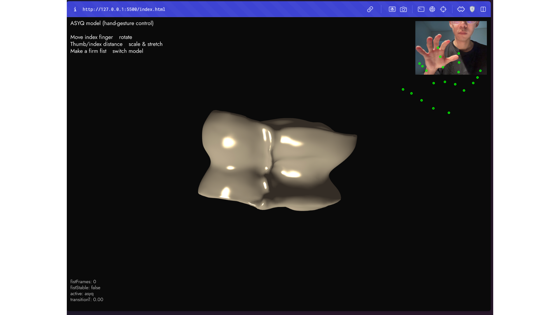
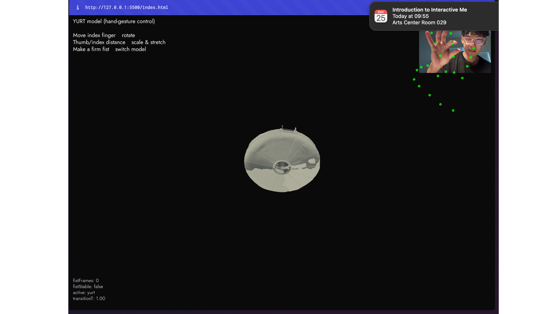
Mädeniet is an interactive project that teaches people about Kazakh culture through movement. The user stands in front of a webcam and controls 3D cultural objects like asyq, kiiz ui, dombyra, and taqiya. The hand becomes the controller. Simple gestures change rotation, scale, color, and even switch between different objects. The goal is to let people learn about culture in a playful way. When the user moves, the objects feel alive. The experience also includes background music from the Kazakh ensemble Dos Mukasan, and a physical arcade button and NeoPixel ring for extra feedback.
Include some pictures / video of your project interaction
 Video.
How does the implementation work?
The project combines p5.js, ml5.js handpose, 3D OBJ models, and an Arduino with a NeoPixel ring. The webcam sends video to the Handpose model. Handpose finds keypoints on the hand. The p5.js code looks at finger positions and turns them into rotation values, scale values, color changes, and model switching. When a fist is detected, the next 3D model appears. When a peace sign is detected, the ambient lighting color changes. When the user pinches their fingers, the model scales. The Arduino reads the arcade button to start the game. It also reads a number from p5.js that tells which 3D model is currently shown. Based on that number, the Arduino changes the NeoPixel ring color.
Description of interaction design
The interaction is simple so anyone can use it. The user raises their hand in front of the webcam.
The gestures:
• Move index finger up or down to rotate the model
• Thumb and index pinch distance changes the model size
• Fist changes to the next 3D model
• Peace sign changes ambient lighting color
• Double tap index finger starts or stops spinning
• Double tap ring finger flips the model
• Double tap middle finger lets the user change music volume by raising or lowering that finger.
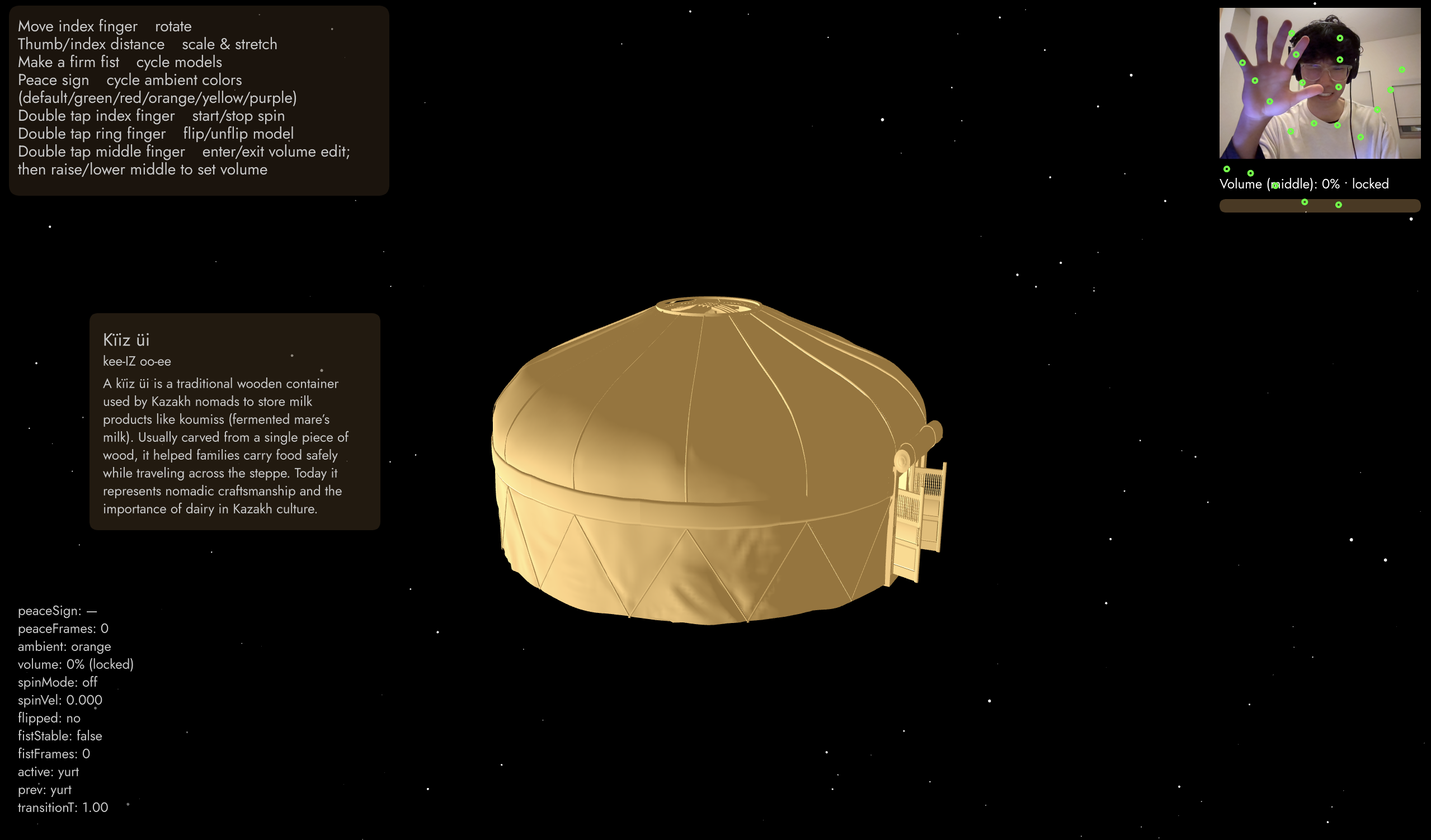
A short guide is always shown on the screen. On the left side the user also sees the cultural meaning of the object they are controlling.
Description of Arduino code and include or link to full Arduino sketch
The Arduino controls two things:
1. It listens to the arcade button. When the user presses the button, Arduino sends “PRESSED” to p5.js. This starts the experience.
2. It listens for model numbers sent from p5.js. If p5.js sends “0”, “1”, “2”, or “3”, the Arduino updates the NeoPixel ring to the matching color. Each cultural object has a color theme. The ring also has a pre game animation (blue and white) and a wave animation during the game (mixing different colors with white to create a pattern).
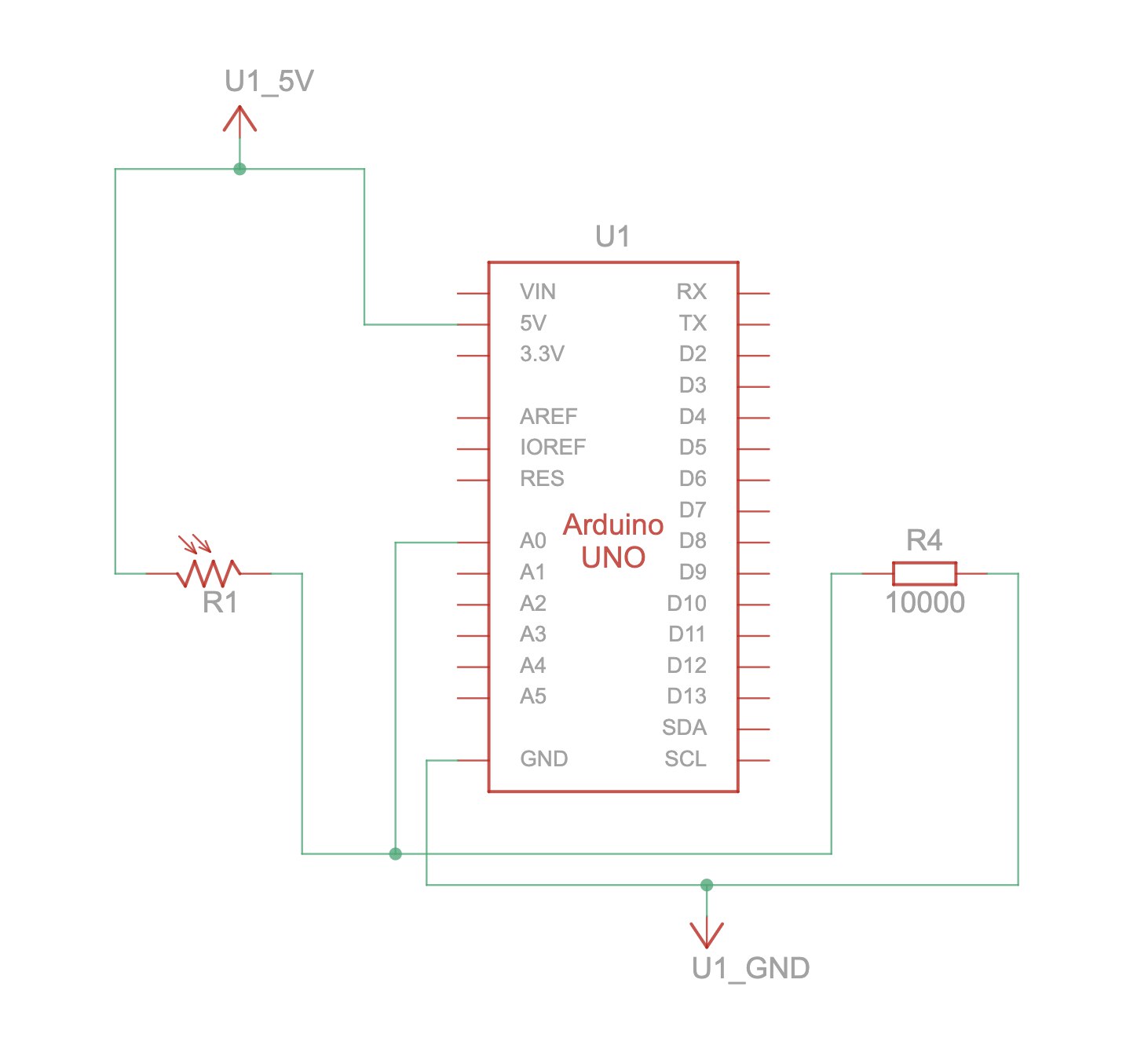
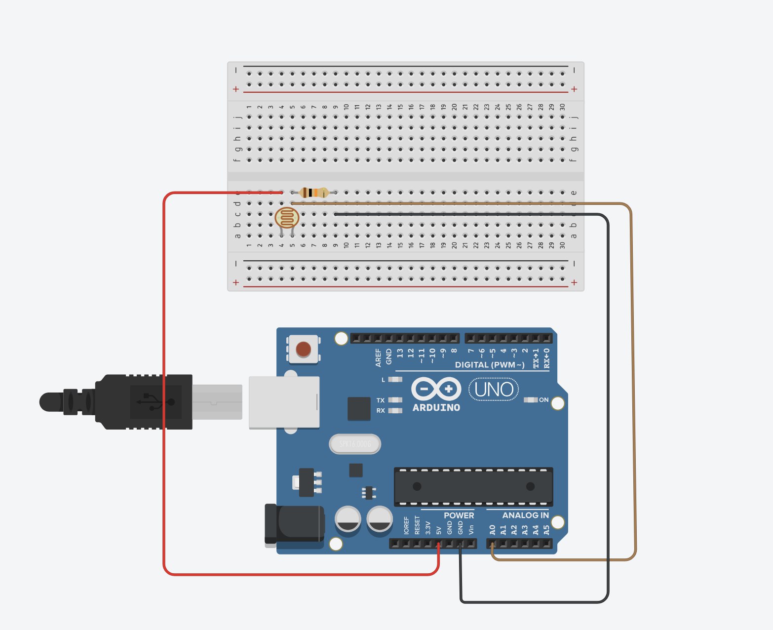
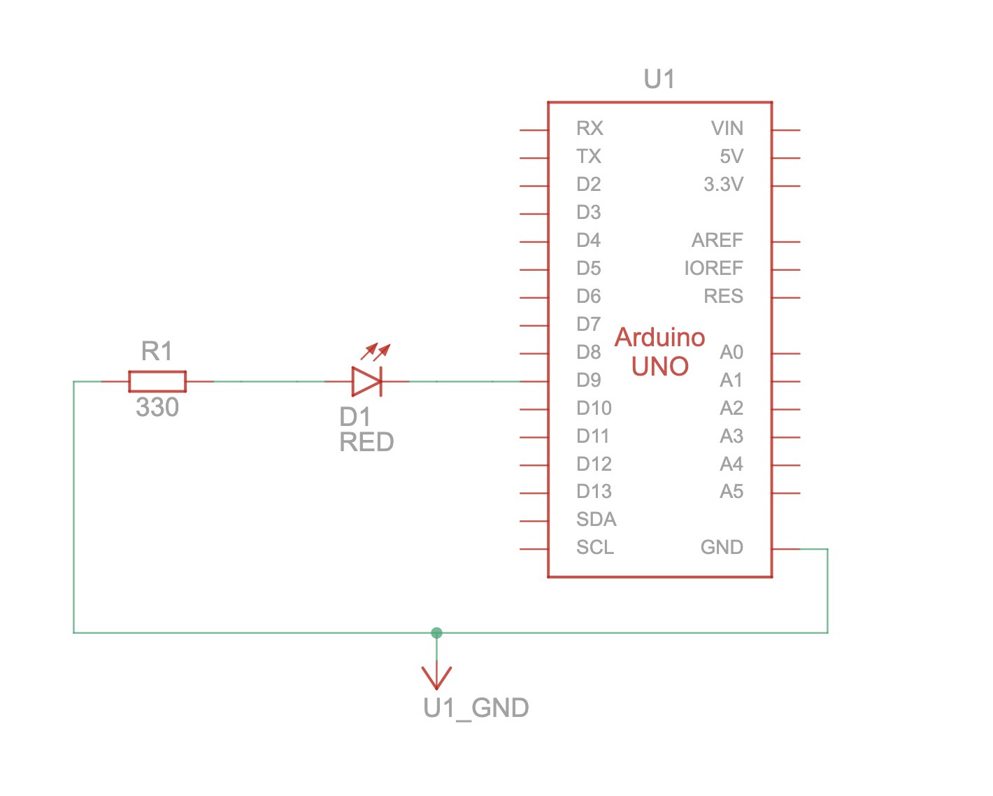
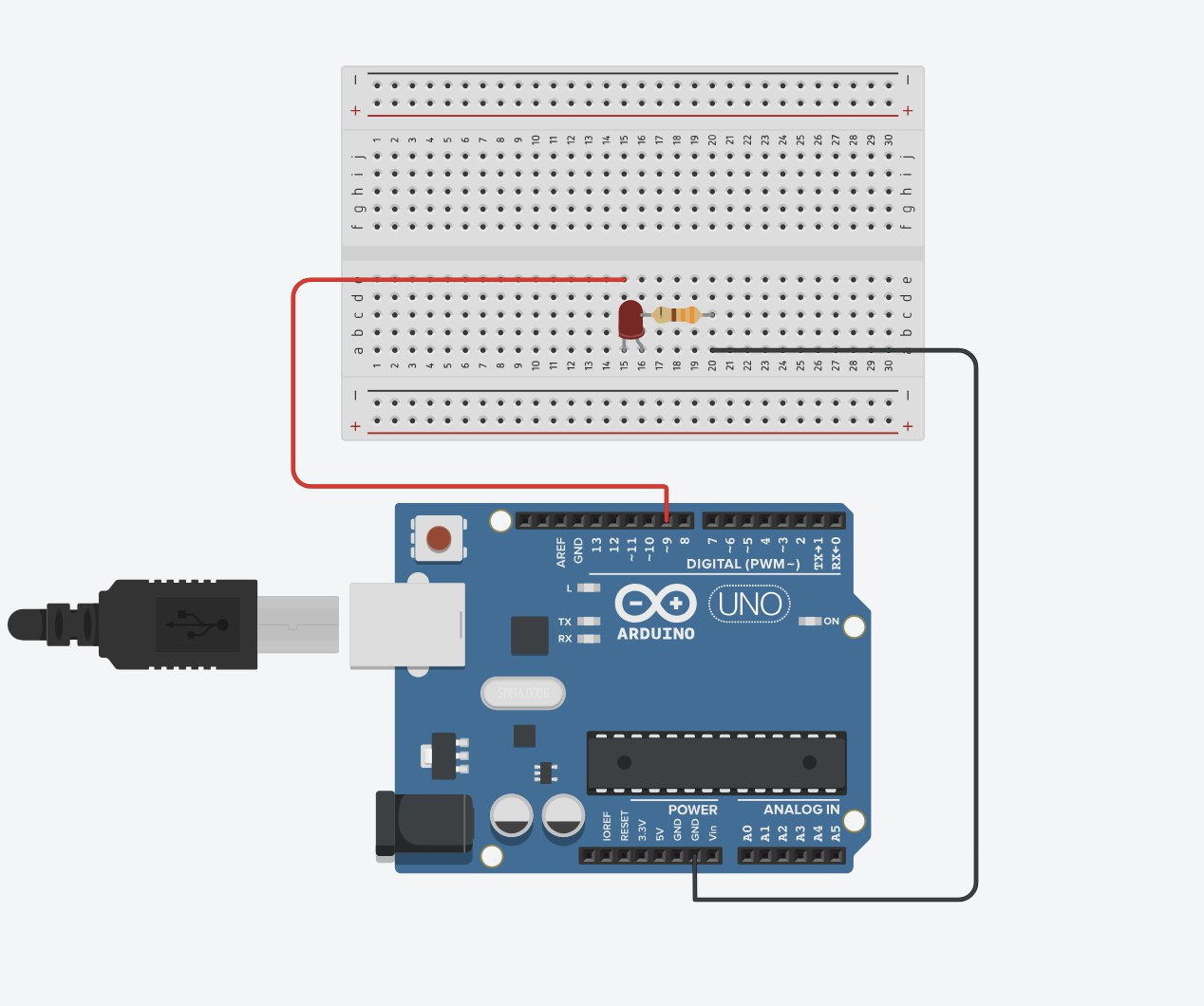
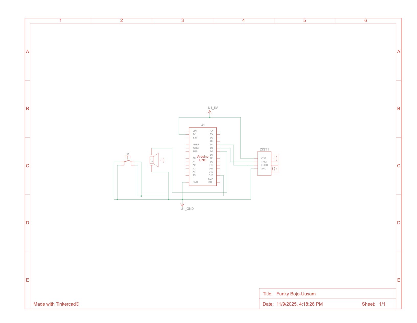
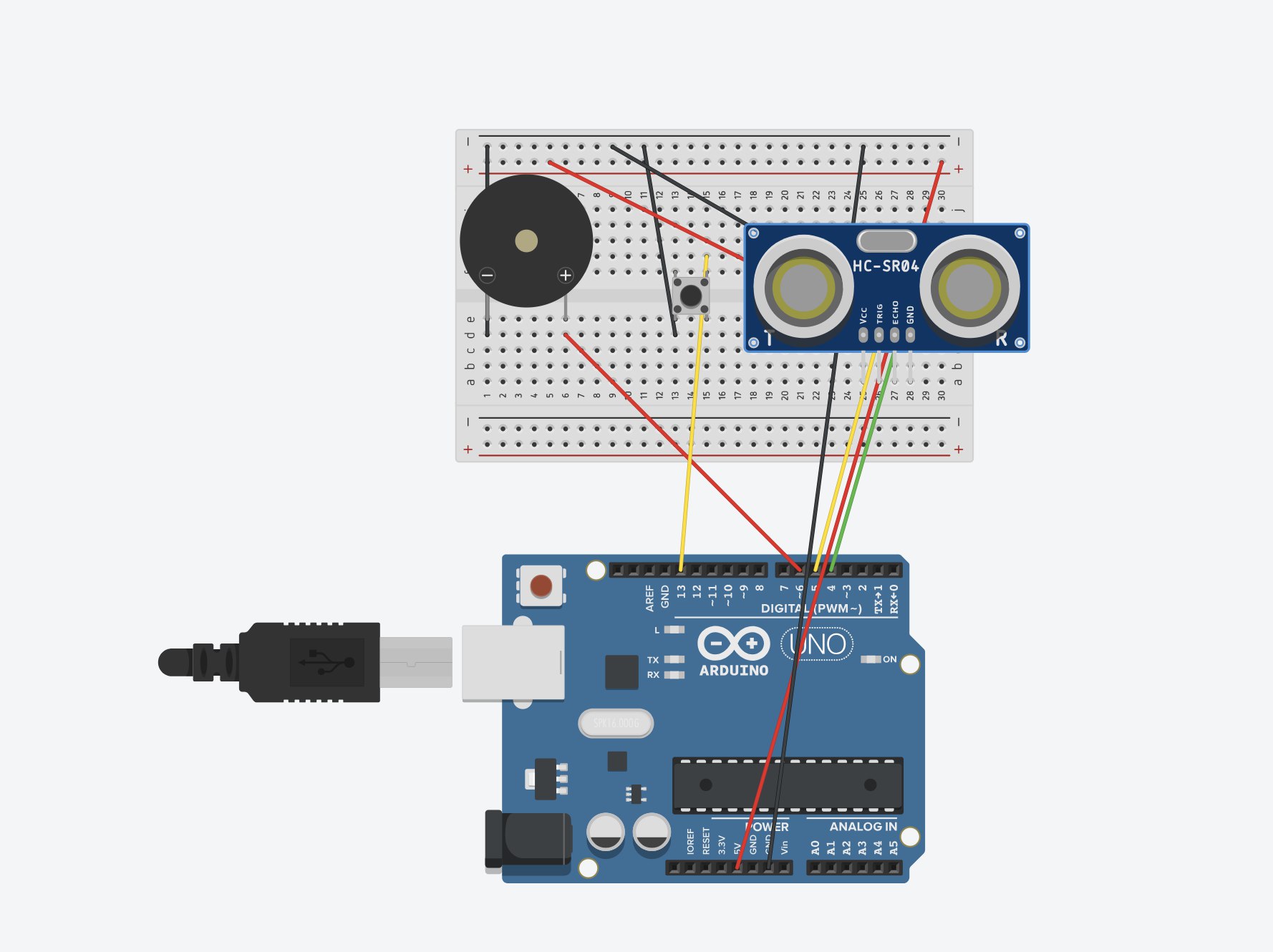
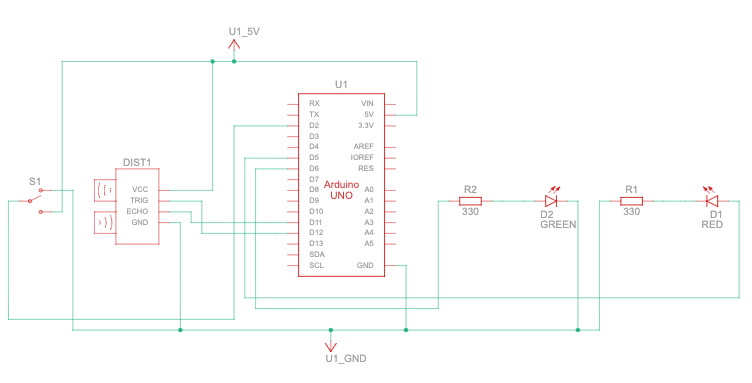
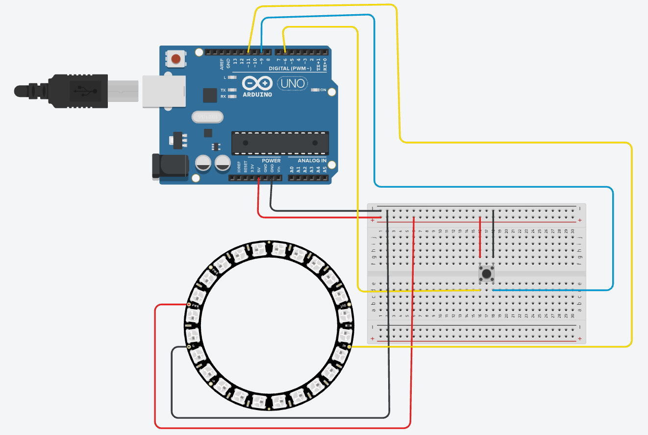
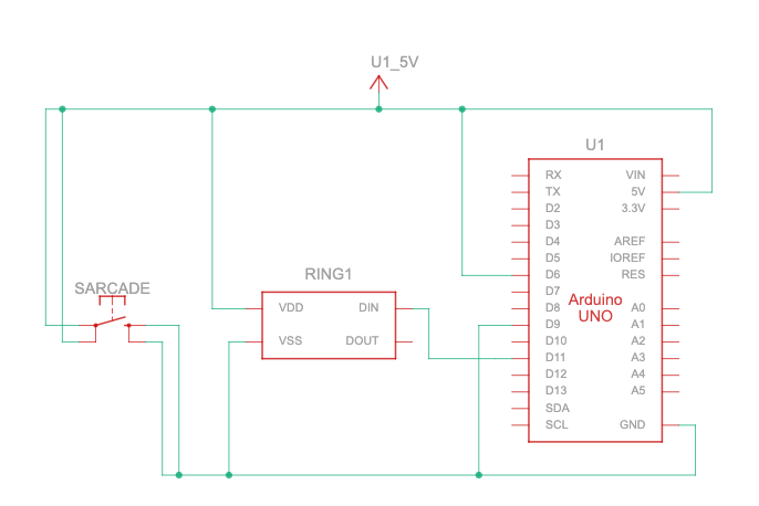
Schematic of your circuit (hand drawn or using tool)
 Description of p5.js code and embed p5.js sketch in post
The p5.js sketch loads the 3D OBJ models, the font, and the audio. It sets up Handpose for gesture tracking. It also handles the Web Serial connection to the Arduino. In draw(), the sketch updates rotation, scaling, color, spin, and transitions. It displays the video preview, model instructions, and cultural information.
Description of communication between Arduino and p5.js
Arduino → p5.js. Arduino sends the line “PRESSED” when the arcade button is pushed. p5.js reads this line and starts the game or resets it. This lets the physical button control the digital experience.
p5.js → Arduino. Whenever the user makes a fist and the model changes, p5.js sends a number like “0”, “1”, “2”, or “3”. Arduino reads that number and updates the NeoPixel ring to the matching color pattern. This creates clear lighting feedback tied to the cultural object on screen.
What are some aspects of the project that you’re particularly proud of?
• I designed creative gestures. For example, the peace sign changes the 3D model color.
• My fist gesture reliably switches between 3D models, which makes the interaction playful and active.
• I combined digital and physical interaction. The NeoPixel ring changes color with each cultural object.
• I included real cultural descriptions so people learn while they play.
• I used Handpose in an expressive way, including pinch scaling, rotation, and double tap detection.
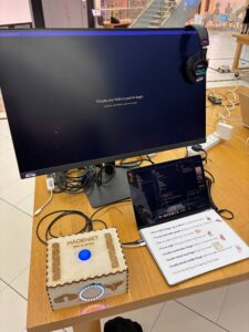
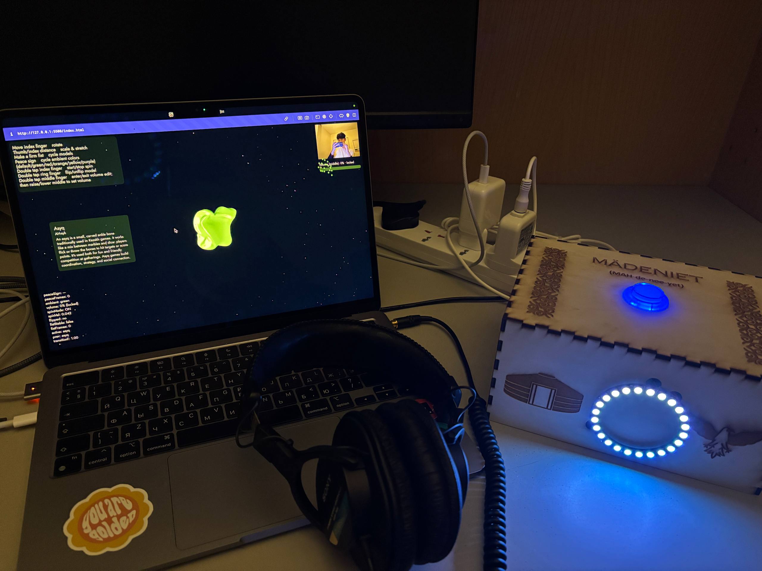
• I built a full installation setup with a laser cut box, arcade button, and headphones, which makes the project feel complete.
• I kept Kazakh heritage at the center of the project.
Use of AI
I used AI throughout the project as a learning tool. It helped me understand how the Handpose model in the ml5.js library works and how to map finger positions to gestures. I was also very interested in WEBGL from the first day of the Intro to IM class. If the professor remembers, during our very first p5.js exercise I was the only student who drew a donut shaped circle using WEBGL. That moment made me want to explore 3D even more. I used ChatGPT to learn how WEBGL works in p5.js and how to combine it with hand tracking. AI also supported me in fixing errors, structuring the code.
What are some areas for future improvement?
I want to add voice commands so the user can say simple words like “next” or “back” to change models without using gestures. I also want to improve the hand tracking. The current ml5.js Handpose model struggles with accuracy and does not support two hands. I tested the MediaPipe Hand Tracking library, which works much better and can track both hands at the same time. Using two hands makes size control feel more natural, and it also opens the possibility for new gestures. For example, I experimented with flipping the model by clapping hands together instead of using a ring finger double tap gesture. I would like to explore this approach further and see if I am allowed to use MediaPipe in the final version of the project.
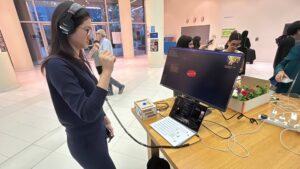
UPD. from IM showcase
It was an amazing experience to see people come and ask questions about my project. I took some pictures and videos, and I installed a large monitor so the project could be viewed more easily for a better experience. I think the Handpose detection was a bit hard for users to understand, even though it felt easy for me since I was the one developing it. Using a different library, such as MediaPipe, would probably make detection much easier for first-time users. The hand gestures like double-bending the index, ring, or middle finger to spin or flip the 3D model, or even manipulating the volume of the background music were fun to implement, but not always intuitive for newcomers. Still, people said it was one of the coolest projects at the IM showcase, so I’m really glad. Right after the showcase, I also had my piano recital, so I was a bit stressed, but everything went well.