A Walk Through Time: Final Project Documentation
Concept
The idea behind A Walk Through Time is to let the viewer control the flow of time with simple hand gestures. When the viewer waves their hand on one side, time moves forward. When they wave on the other side, time reverses. When no one interacts, time pauses. The system changes both the physical world and the digital world at the same time.
The physical clock hand moves using a stepper motor. A growing plant moves up and down using a DC motor and a telescoping cylinder system. On the screen, a surreal p5.js world shows time moving with colors, waves, particles, and a glowing abstract clock. Everything stays in sync and reacts at the same moment. The goal was to create one experience where movement, gesture, and time feel connected.
Project Interaction
Interaction description:
- The viewer stands in front of the clock and plant
- Two ultrasonic sensors wait for hand gestures
- Waving on the right makes the clock tick forward and the plant rise
- Waving on the left makes the clock tick backward and the plant collapse
- When the viewer steps away, both the clock and plant pause
- The p5.js visuals shift to match the state: forward, backward, or paused
How the Implementation Works
The system uses two Arduinos, two motors, two sensors, and a p5.js sketch.
Main Arduino
- Reads the left and right ultrasonic sensors
- Decides the time state: FORWARD, BACKWARD, or PAUSED
- Moves the stepper motor to tick the physical clock
- Sends the state through serial as a single character (
F,B, orP) - Sends the same data to the second Arduino
Second Arduino
- Receives
F,B,P - Moves the DC motor to pull or release fishing wire
- This grows or collapses a three-layer telescoping plant
p5.js
- Reads the same serial data from the main Arduino
- Updates the surreal background
- Moves particles, waves, arrows, and an abstract glowing clock
- Lets the viewer see time flowing
Interaction Design
The interaction is very simple. The viewer uses hand gestures to control time.
Right sensor → Time Forward
Left sensor → Time Backward
Both or none → Pause
All outputs reinforce this state:
-
- The physical clock hand moves
- The plant grows or collapses
- The digital world changes color and motion
Arduino Code
Below are the Arduino codes:
#include <Stepper.h>

const int stepsPerRevolution = 2048;
const int ticksPerRevolution = 12;
const int stepsPerTick = stepsPerRevolution / ticksPerRevolution;

Stepper clockStepper(stepsPerRevolution, 8, 10, 9, 11);

enum TimeState { PAUSED, FORWARD, BACKWARD };
TimeState timeState = PAUSED;
TimeState lastSentState = PAUSED;

const int TRIG_RIGHT = 4;
const int ECHO_RIGHT = 5;
const int TRIG_LEFT  = 6;
const int ECHO_LEFT  = 7;

const int DETECT_THRESHOLD_CM = 40;

unsigned long lastTickTime = 0;
const unsigned long tickInterval = 1000;

long readDistanceCM(int trigPin, int echoPin) {
  digitalWrite(trigPin, LOW);
  delayMicroseconds(2);
  digitalWrite(trigPin, HIGH);
  delayMicroseconds(10);
  digitalWrite(trigPin, LOW);
  long duration = pulseIn(echoPin, HIGH, 20000);
  if (duration == 0) return -1;
  return duration / 29 / 2;
}

void sendStateIfChanged() {
  if (timeState == lastSentState) return;
  lastSentState = timeState;
  char c = 'P';
  if (timeState == FORWARD) c = 'F';
  else if (timeState == BACKWARD) c = 'B';
  Serial.write(c);
}

void setup() {
  clockStepper.setSpeed(10);
  pinMode(TRIG_LEFT, OUTPUT);
  pinMode(ECHO_LEFT, INPUT);
  pinMode(TRIG_RIGHT, OUTPUT);
  pinMode(ECHO_RIGHT, INPUT);
  Serial.begin(9600);
}

void loop() {
  unsigned long now = millis();

  long distLeft  = readDistanceCM(TRIG_LEFT,  ECHO_LEFT);
  long distRight = readDistanceCM(TRIG_RIGHT, ECHO_RIGHT);

  bool leftDetected  = (distLeft  > 0 && distLeft  < DETECT_THRESHOLD_CM);
  bool rightDetected = (distRight > 0 && distRight < DETECT_THRESHOLD_CM);

  if (leftDetected && !rightDetected) timeState = BACKWARD;
  else if (!leftDetected && rightDetected) timeState = FORWARD;
  else timeState = PAUSED;

  if (now - lastTickTime >= tickInterval) {
    lastTickTime += tickInterval;
    if (timeState == FORWARD) clockStepper.step(-stepsPerTick);
    else if (timeState == BACKWARD) clockStepper.step(stepsPerTick);
  }

  sendStateIfChanged();
}
const int ENA = 6;
const int IN1 = 5;
const int IN2 = 4;

enum TimeState { PAUSED, FORWARD, BACKWARD };
TimeState state = PAUSED;

byte motorSpeed = 80;

unsigned long lastChangeTime = 0;
const unsigned long maxRunTime = 10000; // 10 seconds

void setup() {
  pinMode(ENA, OUTPUT);
  pinMode(IN1, OUTPUT);
  pinMode(IN2, OUTPUT);
  Serial.begin(9600);
  lastChangeTime = millis();
}

void applyMotorState(TimeState s, byte speed) {
  if (s == PAUSED) {
    digitalWrite(IN1, LOW);
    digitalWrite(IN2, LOW);
    analogWrite(ENA, 0);
  } else if (s == FORWARD) {
    digitalWrite(IN1, HIGH);
    digitalWrite(IN2, LOW);
    analogWrite(ENA, speed);
  } else if (s == BACKWARD) {
    digitalWrite(IN1, LOW);
    digitalWrite(IN2, HIGH);
    analogWrite(ENA, speed);
  }
}

void setState(TimeState newState) {
  if (newState != state) {
    state = newState;
    lastChangeTime = millis();
  }
}

void loop() {
  if (Serial.available() > 0) {
    char c = Serial.read();
    if (c == 'F') setState(FORWARD);
    else if (c == 'B') setState(BACKWARD);
    else if (c == 'P') setState(PAUSED);
  }

  unsigned long now = millis();

  if (state != PAUSED && (now - lastChangeTime >= maxRunTime)) {
    setState(PAUSED);
  }

  applyMotorState(state, motorSpeed);
}
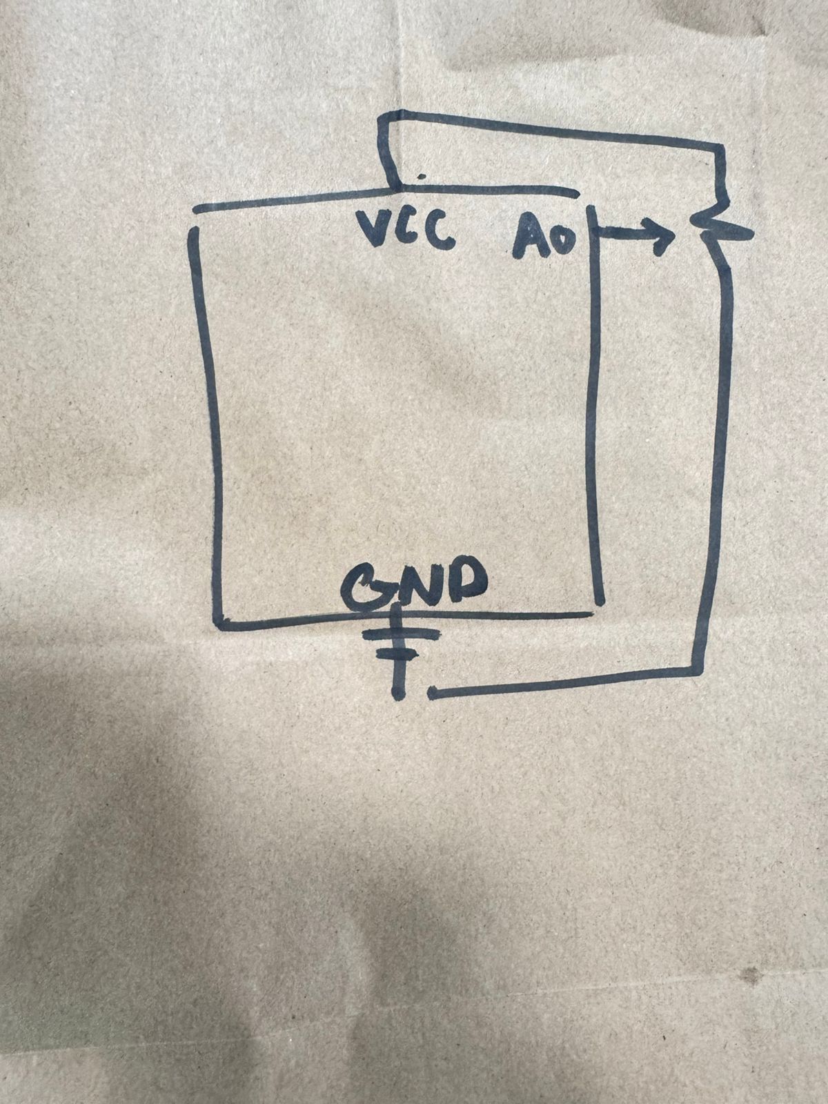
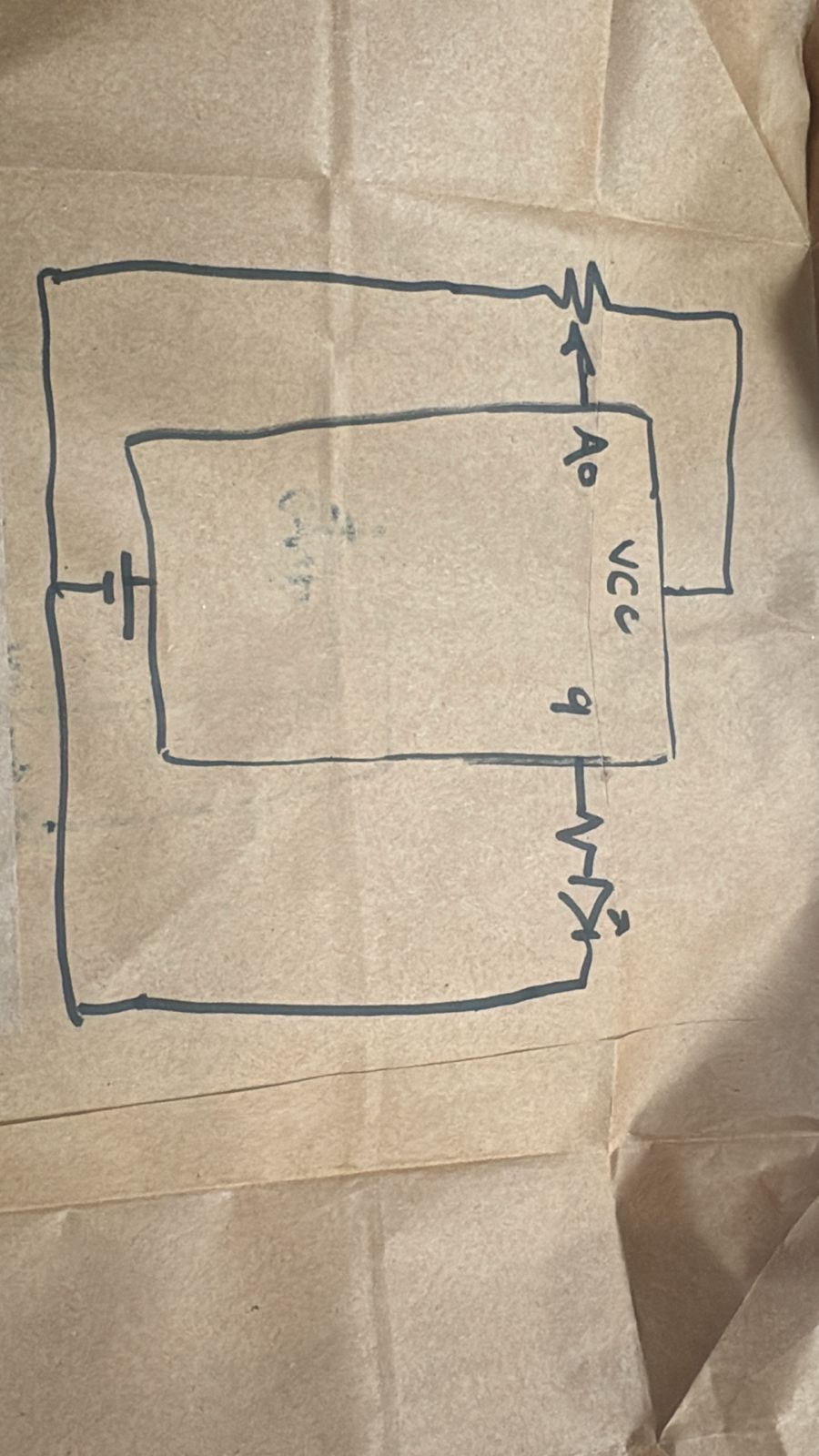
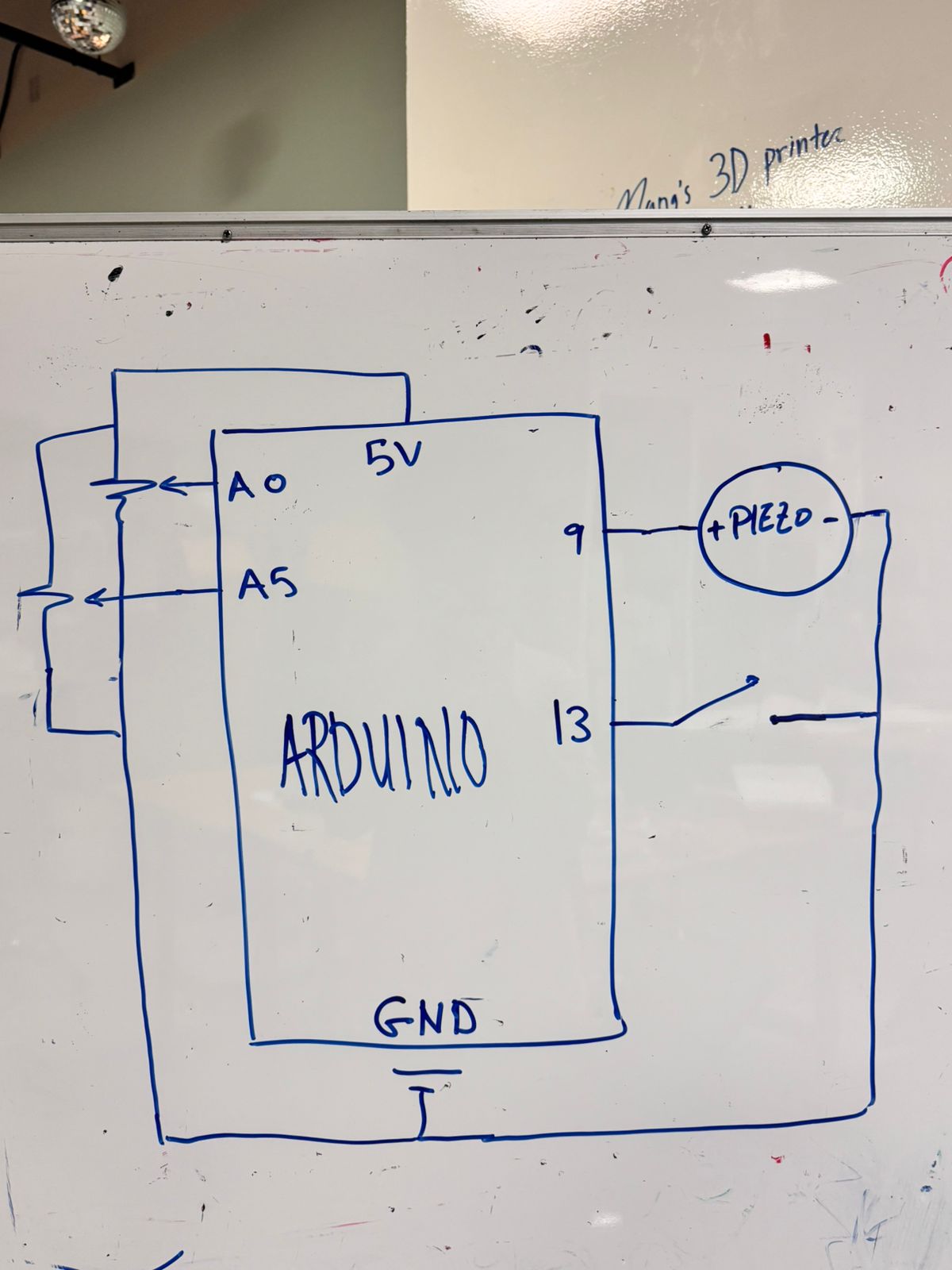
Circuit Schematic
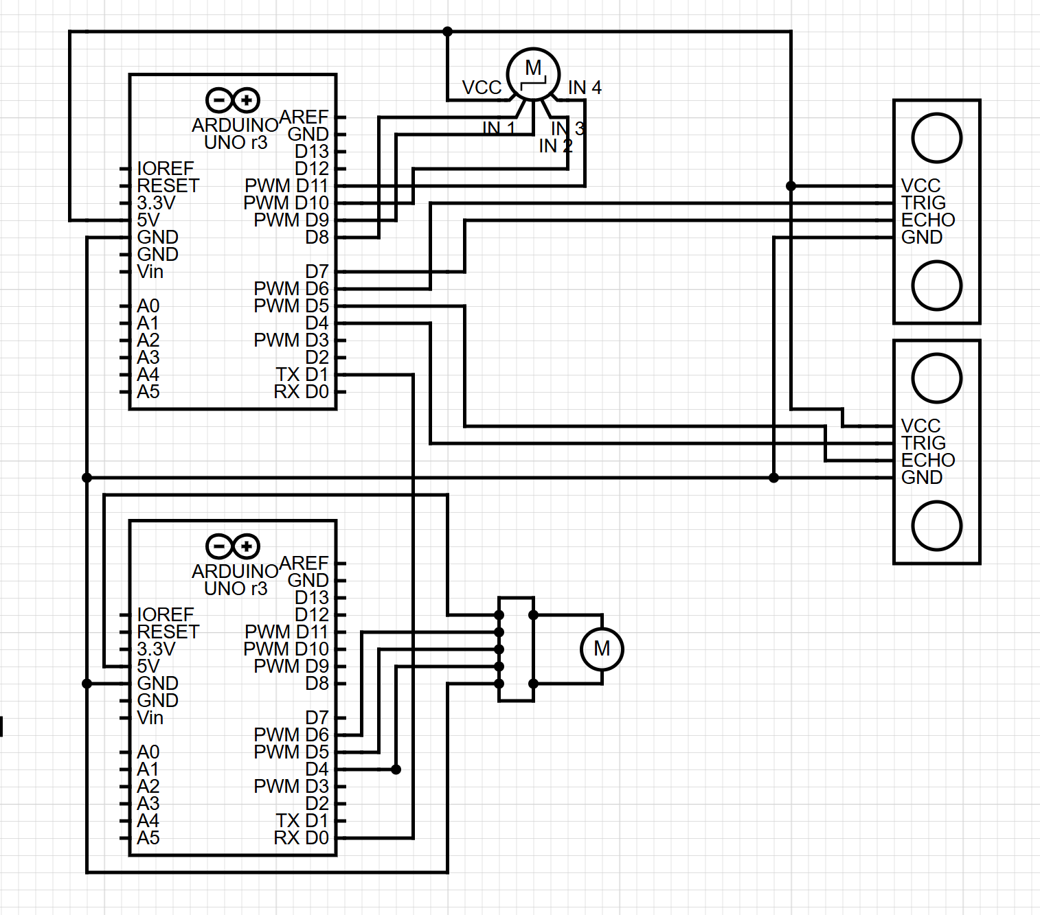
(Diagram made with https://www.circuit-diagram.org/)
breakdown of schematic:
Main Arduino
- Ultrasonic Sensor Left
- TRIG to pin 6
- ECHO to pin 7
- VCC to 5V
- GND to GND
- Ultrasonic Sensor Right
- TRIG to pin 4
- ECHO to pin 5
- VCC to 5V
- GND to GND
- Stepper Motor (with driver)
- IN1 → pin 8
- IN2 → pin 9
- IN3 → pin 10
- IN4 → pin 11
- VCC → 5V
- GND → GND
- Serial Out
- TX (pin 1) → RX of second Arduino
Second Arduino (DC Motor Controller)
- DC Motor Driver
- IN1 → pin 5
- IN2 → pin 4
- ENA (PWM) → pin 6
- Motor output → DC motor
- Vmotor → 5V
- GND → common ground with Arduin
- Serial In
- RX (pin 0) → TX of main Arduino
p5.js Code
- Reads the serial state from Arduino
- Updates the scene
- Changes background colors
- Moves particles and waves
- Animates the digital clock
- Shows arrows for direction
Communication Between Arduino and p5.js
Arduino → p5.js
Sends one character:
'F'— forward'B'— backward'P'— paused
p5.js reads this using the Web Serial API.
When p5.js sees the character, it updates the digital world.
What I Am Proud Of
I am proud of how everything stays in sync.
The telescoping plant mechanism was hard to build, but it works well and gives life to the piece.
The gesture-based control also feels natural, and most users understand the idea at once.
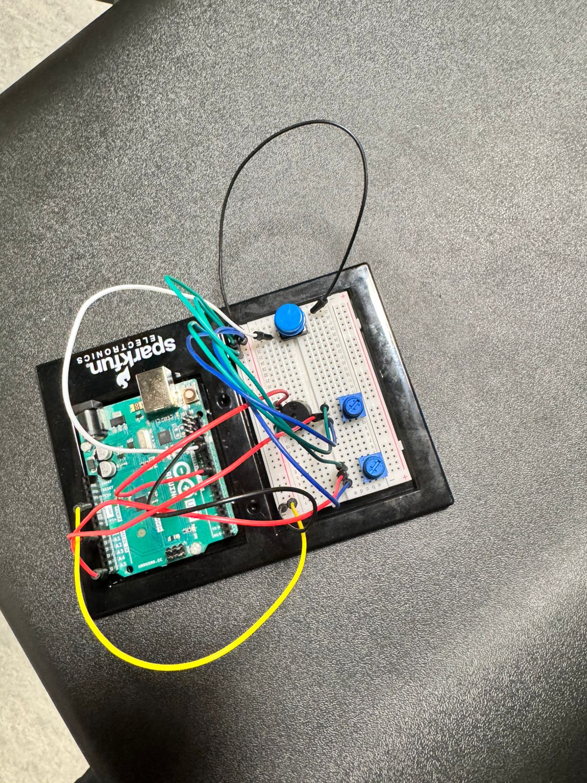
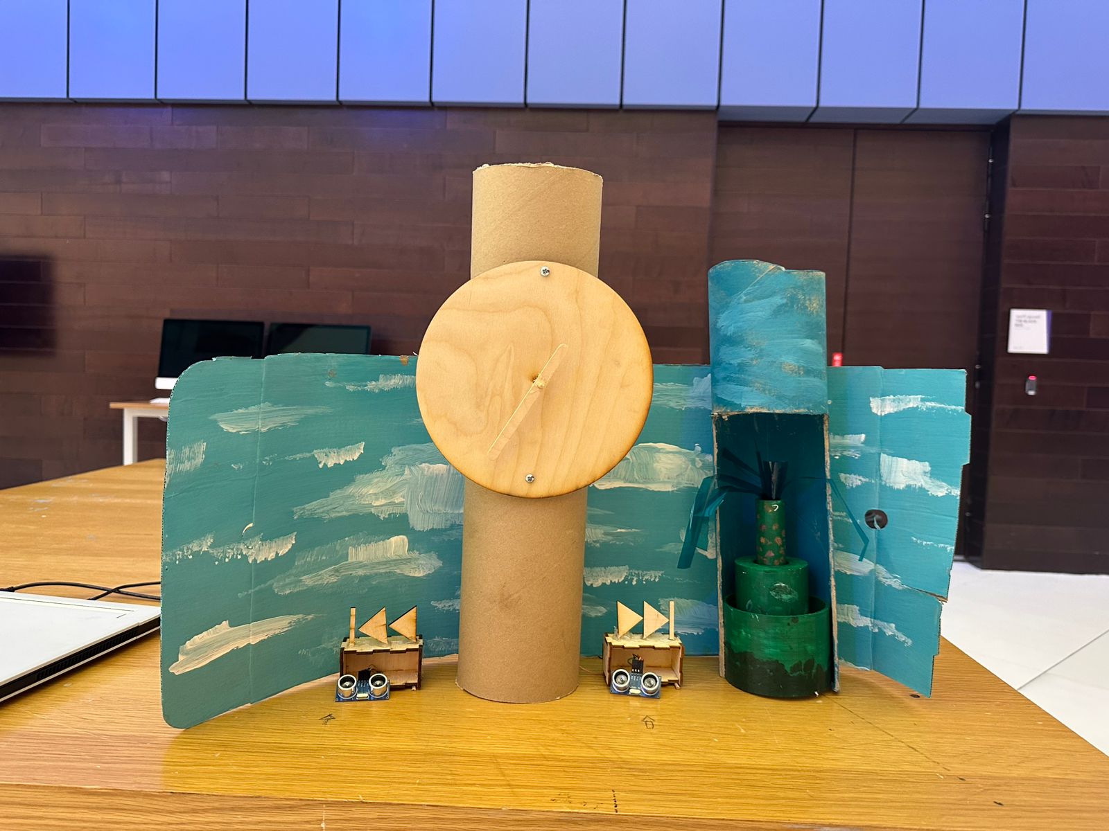
How This Was Made
The clock was laser cut and screwed into a cardboard cylinder. I used an ice cream stick for the hand, which was connected using a skewer to the stepper motor. The boxes for the ultrasonic sensors were laser cut, and I got the design from boxes.py. For the fast forward and rewind icons, I designed them in Illustrator and then laser cut them. I got the idea for the telescoping cylinder from a YouTube short (https://www.youtube.com/shorts/99a4RUlUTm0), and I made a much simpler version that I 3D printed. I used another cardboard cylinder that I cut open to place the plant in and attach the DC motor and wheel at the top. I used acrylic paint, with help from an art major friend, to paint a background scene with the plant and sky.
The p5.js code was written through many tests and changes to connect smoothly with the Arduino using Web Serial. The designs for the scene, the clock visuals, and the interaction layout were made in small steps until everything felt right. The writeup was also done in simple clear language to explain the full system. All media was either created by me, painted by a friend, laser cut from my designs, or made using free online tools.
Areas for Future Improvement
The clock could be painted with a wooden-style finish to look more complete. I also still want to explore the original rotary sensor idea. The plan was to let the user manually rewind the clock by hand, and the system would detect this and move backward. I tested this with gears connecting the rotary sensor to the stepper motor, but the motor was too weak or the gears did not line up. I want to try again with stronger parts.
Finally, while the p5.js visuals look good and support the project, I feel there may be more ways to integrate the digital space with the physical movement. This is something I want to improve in the future.