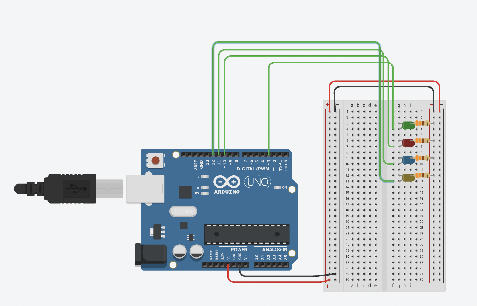
SpaceTrail is a game in which the user plays as a Space Artist by piloting a spacecraft along the screen and paint in a myriad of colors (different shades of blue, yellow, green red and a combination of all). The color of that the player is using is displayed on the Arduino spaceship through the LED lights, each lighting up in accordance the user input (except for the multicolor, which lights up all the lights).
But there’s a trick to this game though: the player have their eyes on the spacecraft and the spacecraft only since if you were actually piloting a ship, you wouldn’t be able to see the trail you leave behind.
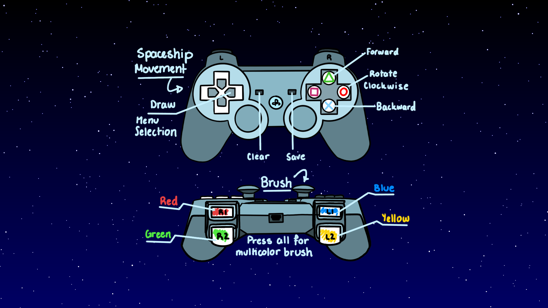
The spacecraft and menu are maneuvered through a PSP Controller which gets the user input and passes it to Processing and Arduino in order to move the spacecraft on the physical world and at the same time create the artwork on the screen.
Once the player feels like they are done with their work, they can save it by pressing the SAVE button on the controller, which will locate the sketch on a folder within the program called “drawings”.
Process
Idea:
We had originally planned to make a car track simulator, however, we wanted to make something more creative and, whilst thinking of how we could incorporate the progress we had made previously (been able to get inputs from a controller using two special libraries in Processing and a Windows computer) to make something a little more spicy.
Armaan came up with the idea of using the car we created as a means to create art. Meanwhile, I wanted to leave the spatial intelligence test element in the project and alas, we came up with SpaceTrail.
We are extremely proud of our work. However, we did have to make a deal with the devil and sacrifice various campus cats (and our own sanity) to have this project ready.
Arduino and Serial Communication
Besides time consuming (to say the least) this project was also extremely painful and required a lot of trial and error, debugging and scratching out ideas to come up with new ones that actually worked. Though we had already made the controls for the car, which would be translated into the spaceship, we had a lot of problems with the serial communication, to the point were we had to re-think the type of input we wanted to get from the controller. We originally wanted to use the joystick as the input for the car movement (left, right, forward and backwards). Nonetheless, since this value had to be mapped, it decreased the speed of the car significantly as it took some time for the new values to reach the Arduino. Furthermore, the button states gave integers of 8 and 0 instead of the designated 1 and 0 booleans that configuration stated which affected the serial communication. Armaan was able to fix this by using the integers are the constrains for the conditions and the serial communication;. He spent two whole days (and most of the night) figuring out how to fix the problems we were having with the serial communication, I can attest.
A great part of our time was concentrated around the serial communication between processing and Arduino (specially after the LED light were incorporated in our model). It was very frustrating because one day the spaceship would be working perfectly, just for it to state (the next day) that it was having issues with variables sent by processing. Additionally, placing in the motors with the wheels was very difficult as the tape would sometimes fail and the wheel would go to the side, thus making movement harder. We solved it by adding an insane amount of 3M tape. It worked out at the end.
This is a video of Armaan placing the inputs of the controller to control the lights.
This is a video of how the car was working after adding the LED’s
Armaan’s hard work paid off because afterwards, we never had a problem with the serial communication (unless it was something like forgetting to plug in the Arduino Port).
Processing
For the processing, we created a stroke object that would be part of an array list that conformed the brush/trail of the spacecraft. Making the controls for the red, blue, green and multicolored options was not that difficult, however the yellow required more thinking since it is a combination of rgb colors.
This is a video of how they looked at the beginning.
We played around some more with the shapes, and once we were happy, we started working on a background that would represent the space theme of our project.
This is how it looked like:
We also changed things from this, like the color and the amount of stars. This became the background of our whole game.
We incorporated this background with the paint brush sketch to make this:
We also included commands to save the drawing and clear the sketch to start a new one.
To save the sketches without erasing the previous one, we create a table that save the number of the sketch, reloads it into the program when the game starts and adds one, to keep count of each sketch and be able to save them in the drawing folder.
We then added the commands for the spaceship to move around leaving a trail. This was very hard, specially because the movement of the spacecraft had to have the same logic as the one that Arduino used to command the motors of the spacecraft. It took Thais a lot of time. Indeed, too much time one could say. But alas, we made it. Thais was so tired however, because she didn’t had suhoor and it was already 5am, that she forgot to record this part. Shame on her.
We then combined both the Arduino and the Processing parts to create our functioning game!
We were so proud of our little guy. He was already drawing. They grow up so fast ;-;
That day we even changed its first wheels. 😭
The Menu
The menu was another very time consuming, but extremely satisfying element of our project. Thais designed the UI for the menu while Armaan place everything and created the logic for the transitions.
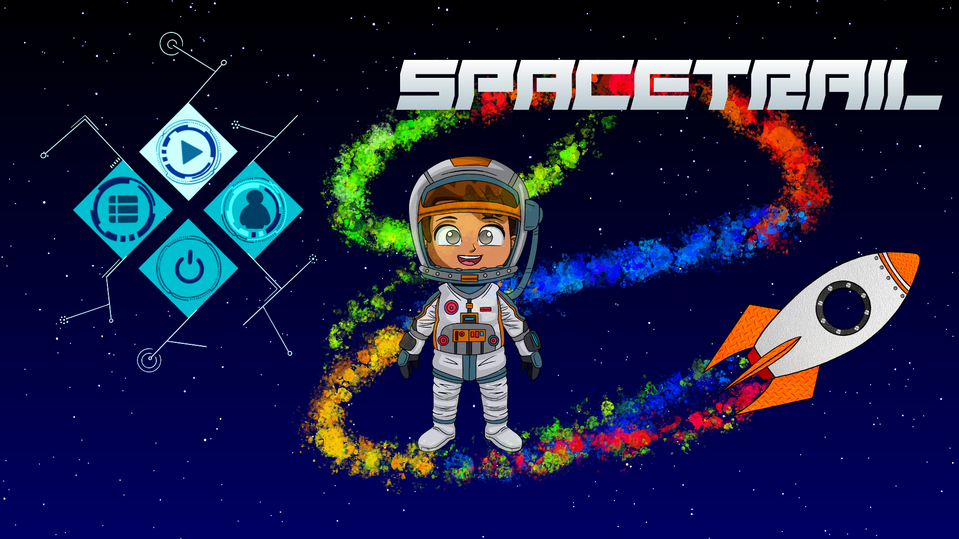
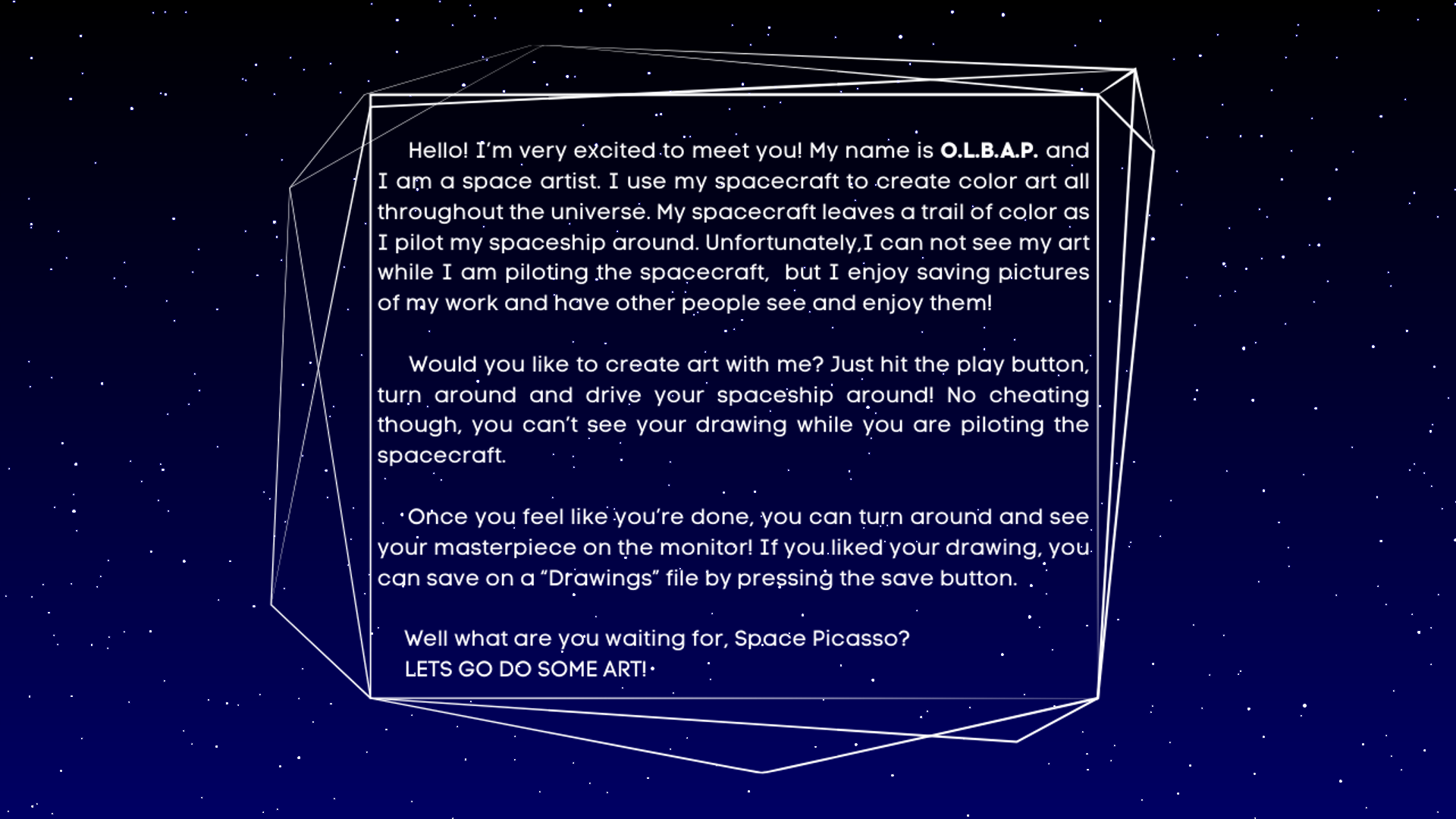
We also created a character named O.L.B.A.P, a space artist that would introduce the user to how the game works and what a space artist does.
This is some of the UI used:
Play UI Button
Exit Button HoverCharacter Information Button HoverController Instruction Button Hover
Controller UI for instructions page
We worked on various versions of the UI and their location in order to make the interface as aesthetic and welcoming as possible. For this, we tried multiple fonts, colors, hover elements and text frames.
The main menu ended up looking like this:
This is the character information page:
Controller Instructions Page
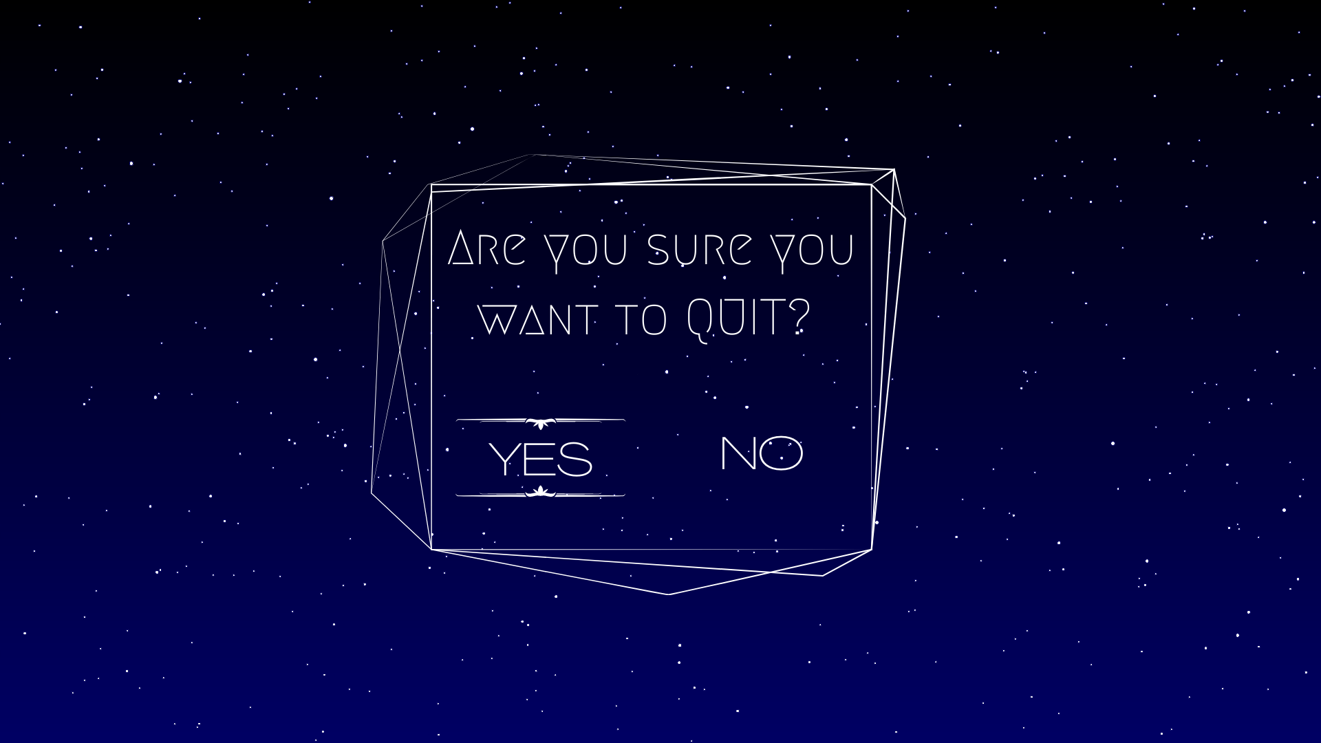
Exit Page
This is the test for the main menu:
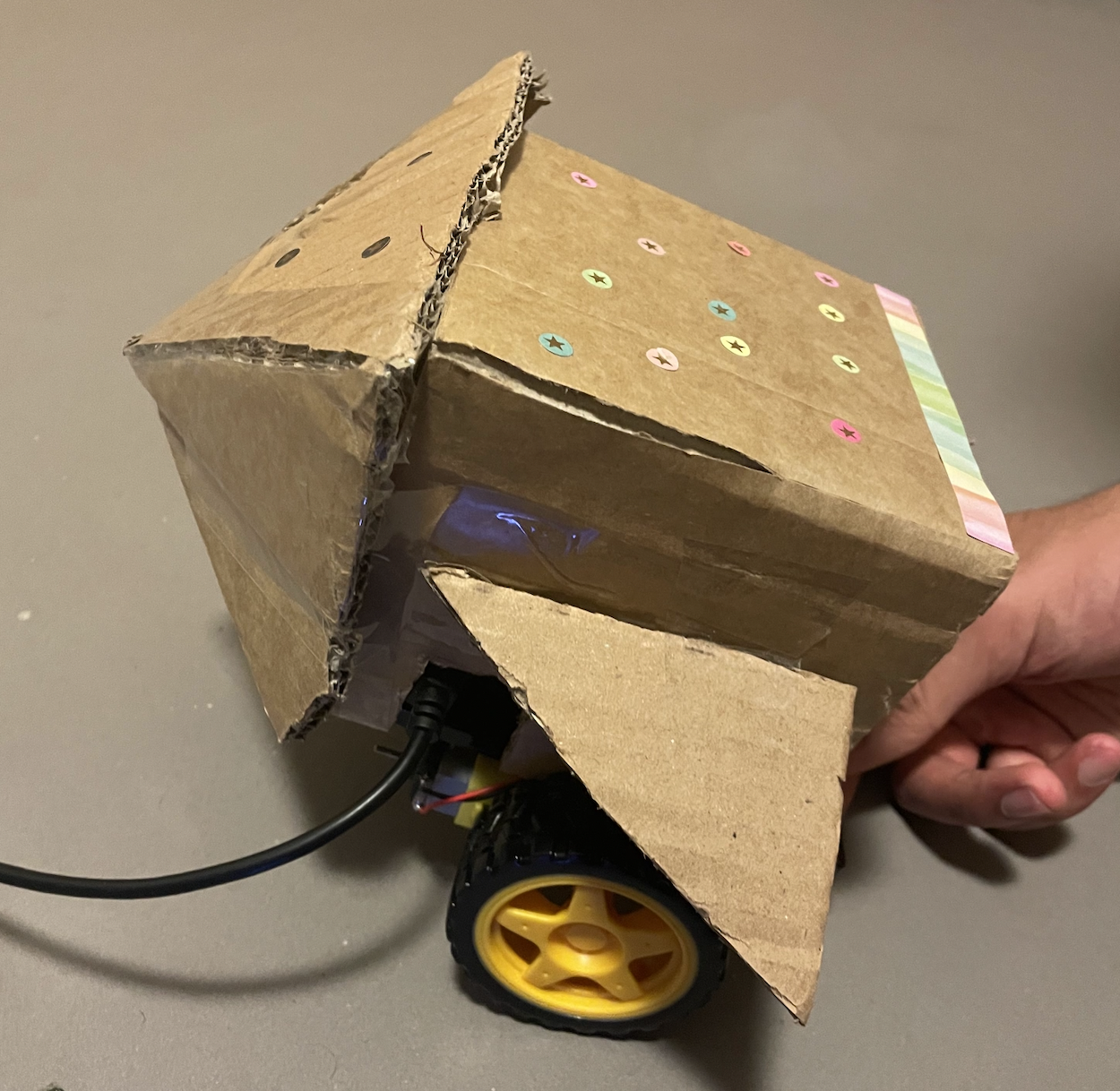
Thais made this attempt to dress our little spacecraft with cardboard. However, we ended up discarding this design because the tape tampered with the motors, but we’ll put the image here so that you can laugh at this sad attempt of a spaceship. We even put stickers to it!
Final Product
Here we have a demo of our project, explained by my amazing partner Armaan.
This is a link to our Notion page were we have the references we used, the minutes of some of our meetings, a few images that we used as inspiration, as well as the several versions of our code.
For the past few days we have been working on the Arduino part of the project and how it communicates with the Processing part related to the controller. We had a lot of technical difficulties because the program would load and then crash or a message would appear saying that the port was busy and thus couldn’t be opened by neither Processing nor the Serial window in Arduino.
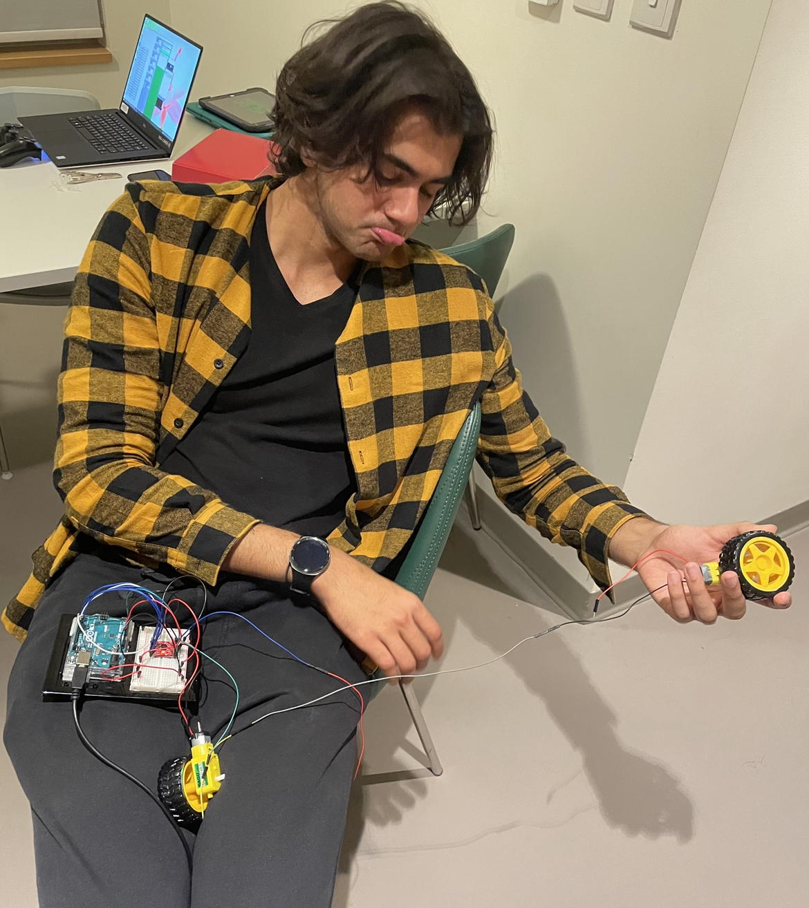
Additionally, the motors sometimes would stop working (wouldn’t move) thus, we couldn’t test the code properly until we got the wheels to move again. We discovered that this was due to the fact that the weight of the Arduino and the bread board was too much for the wheels. We then tried to separate the Arduino and breadboard from the wheels so that they could move without the weight. Unfortunately, this didn’t work since as we tried to extend the length of the wires, many of the extensions would get loose and disconnect, which frustrated our efforts to leave the wheels by themselves. Here is an image of Armaan to demonstrate the sadness we felt when we discovered our brilliant idea was a waste of time:
Since we didn’t want to waste more time, we decided to test the controls with the car in the air in order to check if whether the code we were doing worked or not. The idea is to use the game controller as an input to control the car, map the values of those inputs and then send it to Arduino.
One of the problems we had with this is that even though the joystick of the controller gives values very close to zero when you leave the joystick alone, once those values are mapped, it threw some weird values that made the motors keep on moving. We then had to establish a parameter (between -10 and 10) in order for the motors to activate the brakes. Additionally, the buttons of the controller (which can also be used as brakes) instead of giving a value of either 1 or 0 (as given in the configuration) was instead giving a value of 0 or 8. We also had to fix this by basically hardcoding the fact that the input of the button must be divided by 8.
Testing and fixing the code was very troublesome since every time we disconnected the Arduino the port number changed, so we had to check that the portname was the one we were currently using.
After much struggle, we were finally able to run the code effectively.
What we then decided to do was re-position the wheels below the Arduino in order to balance the weight better and try to see if the car would be able to move. Though it got better, there were still problems with the car stopping after a certain amount of time.
After much pondering, we noticed that the reason why the car was completely stopping was due to the fact that the wheels were curving because the tape we used wasn’t strong enough to hold them in place. We had to get the two sided tape that is used to hang frames from the wall. The position is not perfect, but it got the job done and allowed us to test the car on the ground. There were some issues with turning the car and also with how fast it can go, but after a while of trial and error, we finally succeeded.
Processing
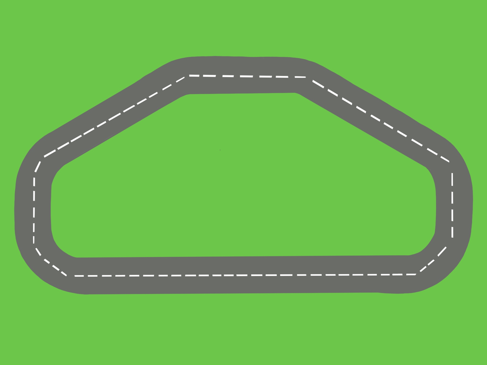
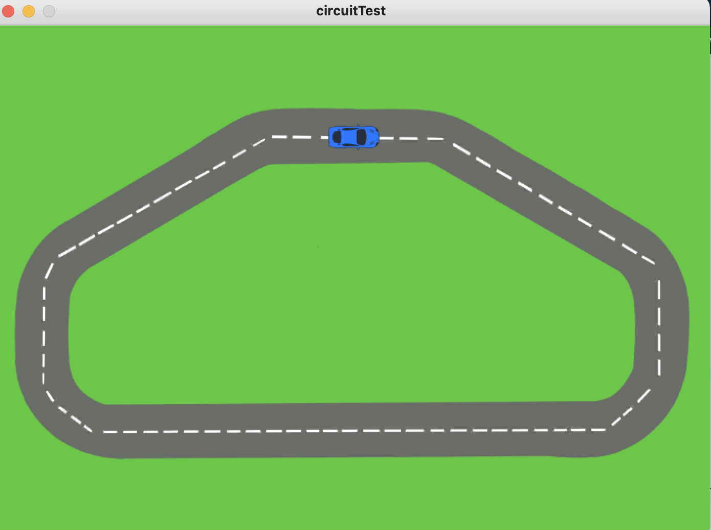
For the processing part, besides using the controller library, we also want to display the road that the car must follow in order for the user to complete the circuit (similar to a spacial intelligence test). For that purpose, we decided to test out how to make sure that the player follows the designated path by using a sample circuit and a car image that will showcase the player’s position in the track.
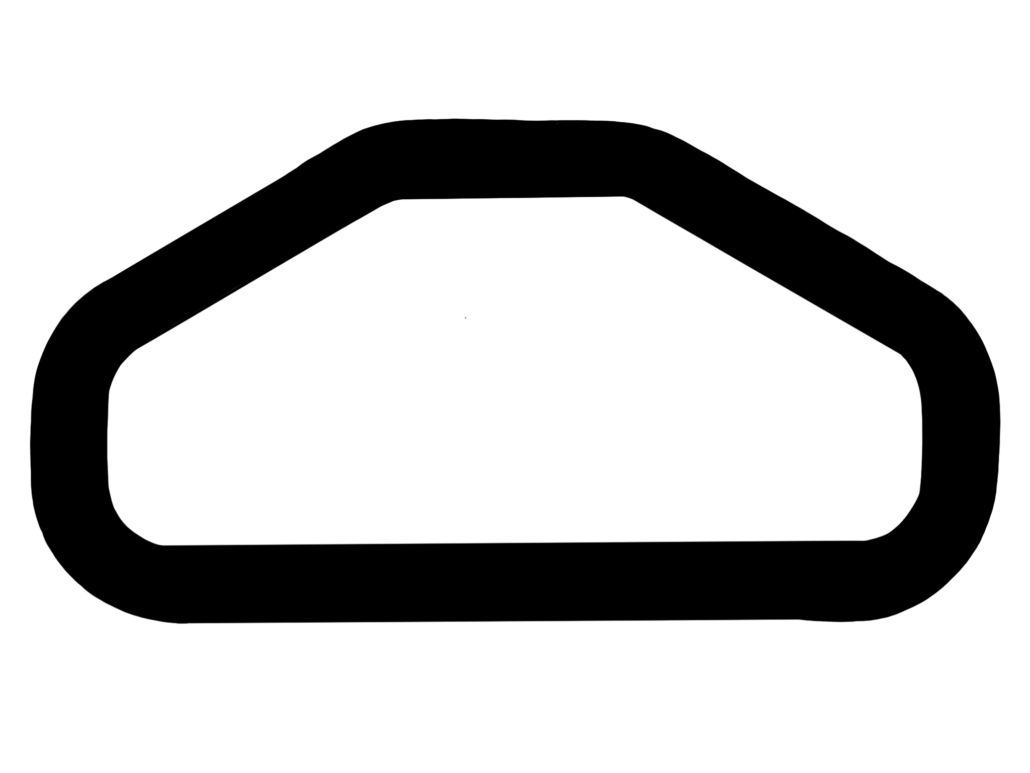
To check the constrains of the player’s track, we decided to use PGraphics. There is a black and white copy of the track and what we do is check if the pixel color of a rectangle at the position of the car matches that of the outside of the track (white pixel on white pixel). Thus, if both pixels are white, the player will not be allowed to go through that zone.
This is the sample circuit
This is the black and white copy of the circuit
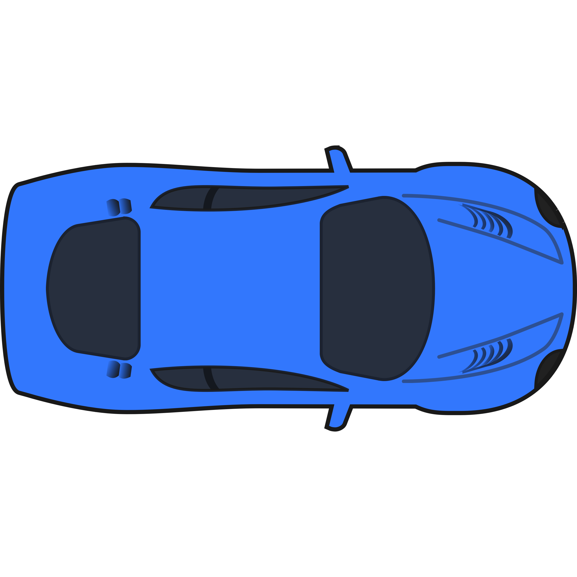
This is the car used to showcase the player position
This is how processing showcased the track with the car along the path.
We are currently working on a more aesthetic model of the track and on a carton cover for the Arduino that will be both for aesthetics and to balance out the weight of the car in order to improve the performance of the car movement.
Note: The controller library that we are using works with our PSP controller only on Windows, so learning how to use the operating software also slowed us down a little, but we are now more comfortable using it (though we still use a Mac to do the Processing side that does not require the controls).
Make something that uses only one sensor on arduino and makes the ellipse in processing move on the horizontal axis, in the middle of the screen, and nothing on arduino is controlled by processing
For this exercise we used the potentiometer to control the movement of the ellipse
Video:
https://youtu.be/HZbzQkfixq8
Arduino
//Exercise 1

const int pinPont = A0;

void setup() {
  Serial.begin(9600);
  Serial.println("0");
}

void loop() {
  while (Serial.available()) {
    if (Serial.read() == '\n') {

      //read the values of the potentiometer
      int sensor = analogRead(pinPont);
      delay(1);
      //print the value
      Serial.println(sensor);
    }
  }
}
Processing
//Exercise 1
import processing.serial.*;
Serial myPort;
int xPos = 0;
int yPos;

void setup() {
  size(960, 720);
  printArray(Serial.list());
  String portname=Serial.list()[3]; // "/dev/cu.usbmodem101"
  println(portname);
  myPort = new Serial(this, portname, 9600);
  myPort.clear();
  myPort.bufferUntil('\n');
}

void draw() {
  background(255);
  yPos = height/2;
  ellipse(xPos, yPos, 30, 30);

}

void serialEvent(Serial myPort) {
  String s=myPort.readStringUntil('\n');
  s=trim(s);
  if (s!=null) {
    //read value from Arduino (potentiometer)

    println(s);
    int value = int(s);

    //map the value to a position in range of the width
    xPos=(int)map(value, 0, 1023, 0, width);
  }
  myPort.write("\n");
}
Exercise 2
Make something that controls the LED brightness from processing.
For this exercise we used the x value of the position of the mouse to control the brightness of the LED.
Video: https://youtu.be/oJ8sW842y5c
Arduino
//Exercise 2

int ledPin = 5;

float brightness;

void setup() {
  Serial.begin(9600);
  Serial.println("0");
  pinMode(ledPin, OUTPUT);
}

void loop() {
  while (Serial.available()) {
    //get the brightness value from processing
    brightness = Serial.parseFloat();

    if (Serial.read() == '\n') {
    //turn on the LED with the given brightness
      analogWrite(ledPin, brightness);
      Serial.println(brightness);
    }
  }
}
Processing
//Exercise 2
import processing.serial.*;
Serial myPort;
int xPos = 0;
int yPos;

int brightness;

void setup() {
  size(960, 720);
  printArray(Serial.list());
  String portname=Serial.list()[3]; // "/dev/cu.usbmodem101"
  println(portname);
  myPort = new Serial(this, portname, 9600);
  myPort.clear();
  myPort.bufferUntil('\n');
}

void draw() {
  background(255);

  //map the mouseX position to the range of birghtness of the LED
  brightness = int(map(mouseX, 0, width, 0, 255));

  yPos = height/2;
  ellipse(mouseX, yPos, 30, 30);
}

void serialEvent(Serial myPort) {
  String s=myPort.readStringUntil('\n');
  s=trim(s);

  //write brightness so that Arduino can use it
  myPort.write(brightness+ "\n");
}
int left = 0;
int right = 0;

int light1 = 0;
int LED1 = LOW;

void setup() {
  Serial.begin(9600);
  Serial.println("0,0");
  pinMode(2, OUTPUT);
  pinMode(5, OUTPUT);
}

void loop() {
  while (Serial.available()) {
    //    right = Serial.parseInt();

    //get whether LED should be turned on from Processing
    light1 = Serial.parseInt();

    Serial.println(light1);

    if (Serial.read() == '\n')
    {

      if (light1 == 1)
      {
        LED1 = HIGH;
      }
      else
      {
        LED1 = LOW;

      }
      digitalWrite(5, LED1);

      //get the vvalues from the potentiometer
      int sensor = analogRead(A0);
      delay(1);

      //      delay(1);
      Serial.println(sensor);

      //      Serial.print(',');
      //      Serial.println(sensor2);

      //Serial.println(LED1);
    }
  }
}
Processing
import processing.serial.*;
Serial myPort;

PVector velocity;
PVector gravity;
PVector position;
PVector acceleration;
PVector wind;
float drag = 0.99;
float mass = 50;
float hDampening;
boolean light;

int valueCapacitor;

void setup() {
  size(640,360);
  noFill();
  position = new PVector(width/2, 0);
  velocity = new PVector(0,0);
  acceleration = new PVector(0,0);
  gravity = new PVector(0, 0.5*mass);
  wind = new PVector(0,0);
  hDampening=map(mass,15,80,.98,.96);
  printArray(Serial.list());
  String portname=Serial.list()[3];
  println(portname);
  myPort = new Serial(this,portname,9600);
  myPort.clear();
  myPort.bufferUntil('\n');
}

void draw() {
  background(255);


  if (!keyPressed){
    wind.x= valueCapacitor;
    velocity.x*=hDampening;
  }


  applyForce(wind);
  applyForce(gravity);
  velocity.add(acceleration);
  velocity.mult(drag);
  position.add(velocity);
  acceleration.mult(0);
  ellipse(position.x,position.y,mass,mass);
  if (position.y > height-mass/2) {
      velocity.y *= -0.9;  // A little dampening when hitting the bottom
      position.y = height-mass/2;
    }

   if (position.y == height - mass/2){
     light = true;
   }
}

void applyForce(PVector force){
  // Newton's 2nd law: F = M * A
  // or A = F / M
  PVector f = PVector.div(force, mass);
  acceleration.add(f);
}

void keyPressed(){
  if (keyCode==LEFT){
    wind.x=-1;
  }
  if (keyCode==RIGHT){
    wind.x=1;
  }
  if (key==' '){
    mass=random(15,80);
    position.y=-mass;
    velocity.mult(0);
  }

}

void serialEvent(Serial myPort) {
  String s=myPort.readStringUntil('\n');
  s=trim(s);

  if (s!=null) {
    int value = int(s);
    valueCapacitor = (int)map(value, 0, 1023, 0, width*.01);
  }

  // we need to use velocity,y so that the light turns off when it is not moving
  // if we use position, the blinking is delayed
  if (round(velocity.y) < 0) {
    myPort.write(1 + "\n");
    println(1);
  } else {
    myPort.write(0 + "\n");
    println(0);
  }
}
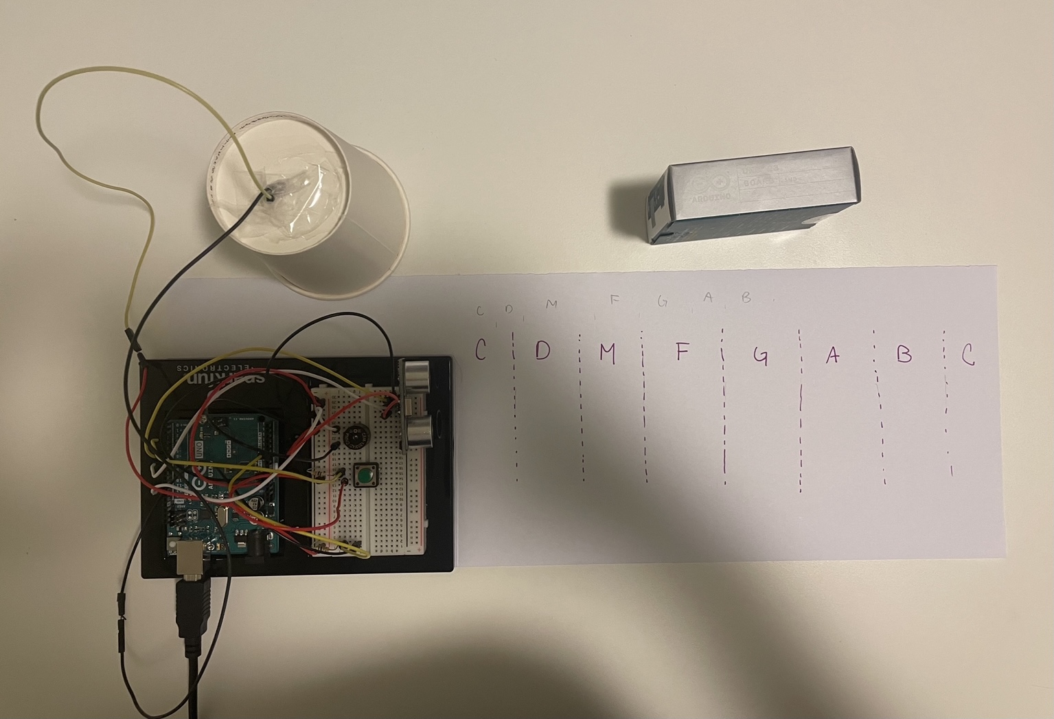
This is an instrument (don’t ask me the name) in which the user can play by utilizing a straight object and locating it at a certain position to play a note. The user can also distort that sound by turning the cup if so they wish.
Idea:
I actually got the inspiration from the clarinet. I wanted something that would be able to play in between the ranges of notes. However, at the end I think that I tried to simulate a piano more. I wanted to use the ultrasonic sensor to play the main notes and then have something similar to a pedal to change them. Now it is more of a distorter than a pedal, but the idea is there.
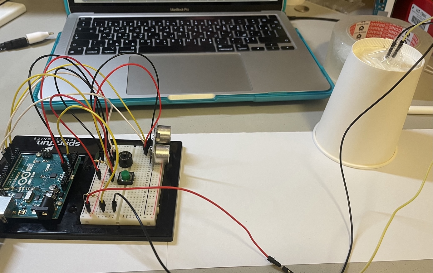
This is how the project looks like from the player’s perspective.
Process
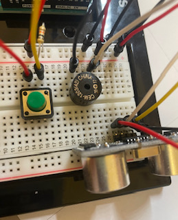
I started by adding an ultrasonic sensor and a speaker to the circuit. (Please ignore the capacitor, it was there for class). I learned how to send and receive waves with the sensor in order to calculate distance. Afterwards, I made an array of sounds (middle C section) and mapped the distance to the number of notes in the array in order to assign a specific note to each distance. I then tested it out with my hand.
The sensor did not gave perfect values so there was a need to clean the information that it was getting. Even then there were still values that were off and I found it better to use a straight surface rather than my hand to make the sounds.
It was very difficult to control when a sound would change only with that so I added a button so that the instrument plays only when the button is pressed.
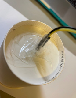
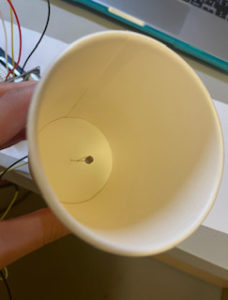
I thought that it would be interesting if the user could modify the pitch of the note by using some sort of additional feature and after much pondering, I decided to use the photosensor. To have better control of the amount of light received I choose to put the photosensor inside a cup. It was a very weird thing to do, specially with all the tape and I had to use female jumper wires for this.
Then I put it all together: the code for the ultrasonic sensor and that for the distortion (photosensor). This part was by far the hardest because merging them messed up some of the sounds and I had to find a way to make the notes sound normal when the photosensor is in the rest position. It took a lot of experimentation and debugging to get this part right. I still think there are better ways of doing what I did, but it works.
This is how it looked at the end:
For a better user experience, I decided to add the location of each of the notes as can be seen in the first image of this post.
Challenges:
SO MANY. This was a very stressful process because one moment something was working and the next everything was crashing.
Figuring out what to do for the project in the first place.
My ultrasonic sensor throws random values most of the time, even when I refined the noise there still were some values that were off, but 7amdullah it didn’t interfere with the program that much for playing. I also used a straight surface rather than my hand to play from the distance sensor side which helped regulate the values.
Been able to play a melody without the program crashing
The button sometimes continued to read pressed even though it wasn’t (specially after a couple minutes of running the program).
Combining the distortion effect of the photosensor with the actual note been played from the distance.
Just figuring out how to do things in general. (So many ideas, so few good ones ;-; cries in Arduino)
I am very bad with tape and keeping the photosensor in contact with the wire.
I had other problems (as you will noticed from all the prints in my code) but I am so glad that it now works that I don’t want to remember the trauma.
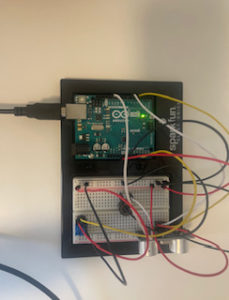
Not my most aesthetic project: There are wires everywhere!
Circuit
*Note: in this image the ultrasonic sensor is inverted because I could’t flip its image. Furthermore, there is not cup for the photosensor since TinkerCad doesn’t have that feature
Final Result
Code
# include "pitches.h"

int echoPin = 5;                //pin of the echo of the distance sensor: receives the wave
int trigPin = 6;                //pin of the trigger of the distance sensor: sends the wave
long duration;                  //duration of sending and receiving the wave
long distance;                  //distance calculate by the sensor

int buttonPin = 2;              //pin of the button

const int numReadings = 10;     //number of readings to get the average

int readings[numReadings];      // the readings from the analog input
int readIndex = 0;              // the index of the current reading
int total = 0;                  // the running total
int average = 0;                // the average
int noteFreq = 0;               // the final frequency used to play the note

int photocensorPin = A0;        //pin of the photosensor
float photoValue;               //value received from the photosensor

void setup() {

  pinMode(echoPin, INPUT);
  pinMode(trigPin, OUTPUT);

  pinMode(buttonPin, INPUT);

  pinMode(photocensorPin, INPUT);


  //int notes[8] = {NOTE_C4,NOTE_D4,NOTE_E4,NOTE_F4,NOTE_G4, NOTE_A4, NOTE_B4, NOTE_C5};

  //int sound = 0;
  //tone(11, notes[sound]);

  // you have to round this
  // it allows you to access the
  //you go up one note to change to a Sharp/bemol
  // (pow(2,(noteNumber-69.)/12.)*440)

  // initialize all the readings to 0
  for (int thisReading = 0; thisReading < numReadings; thisReading++) {
    readings[thisReading] = 0;
  }

  Serial.begin(9600);
}

void loop() {

  //PROGRAMMING THE ULTRASONIC SENSOR---------------------------------------------------------

  //send the wave and receive it
  digitalWrite(trigPin, LOW);
  delayMicroseconds(2);
  digitalWrite(trigPin, HIGH);
  delayMicroseconds(10);
  digitalWrite(trigPin, LOW);

  //collect the data of the duration of the pulse
  duration = pulseIn(echoPin, HIGH);

  //convert the duration to distance
  //0.340 is the speed (centimeters per microseconds)
  distance = (duration / 2) * .0340;
  //Serial.println(distance);

  //GETTING VALUES FROM THE PHOTOSENSOR-------------------------------------------------------

  photoValue = analogRead(photocensorPin);
  //Serial.println(photoValue);

  int distortion = map(photoValue, 300, 800, 0, 50);

  //int noteNumber = map(photoValue, 0, 1023, 0, 120);
  //int note = (pow(2, (noteNumber - 69.) / 12.) * 440);
  // tone(11, note);


  //UPLOAD NOTES-----------------------------------------------------------------------------
  //make an array with the note pitches
  int notes[8] = {NOTE_C4, NOTE_D4, NOTE_E4, NOTE_F4, NOTE_G4, NOTE_A4, NOTE_B4, NOTE_C5};

  //if the parst ten values are some note and it doesn't change, then leave that note
  //if the note changes for more than 3 than change the note

  //CHECK BUTTON STATE-----------------------------------------------------------------------
  bool currButtonState = digitalRead(buttonPin);
  //Serial.println(currButtonState);

  //PLAY INSTRUMENT--------------------------------------------------------------------------

  // if button is not pressed and distance is not within range, don't play anything
  if (distance < 0 && distance > 20 && !currButtonState)
  {
    noTone(11);
  }
  //play the note
  else
  {
    //this variable changed the distance to a value for the array
    int sound = map(distance, 0, 20, 0, 8);
    //Serial.println("Distance");
    //Serial.println(distance);
    //Serial.println("Sound");
    //Serial.println(sound);

    total = total - readings[readIndex];

    // read from the sensor:
    readings[readIndex] = sound;

    // add the reading to the total:
    total = total + readings[readIndex];

    // advance to the next position in the array:
    readIndex = readIndex + 1;

    // if we're at the end of the array...
    if (readIndex >= numReadings) {
      // ...wrap around to the beginning:
      readIndex = 0;
    }

    // calculate the average:
    average = total / numReadings;

    //Serial.print(sound);
    //Serial.print(" ");
    //Serial.println(average);

    //Serial.println(distortion);

    //Change NOTE FREQUENCY

    //if there it distortion
    if (distortion > 0, distortion < 50)
    {
      //add the distotion to the note
      noteFreq = notes[average] + distortion;
    }
    else
    {
      //just have the note without distortion
      noteFreq = notes[average];
    }

    //if button is pressed
    if (currButtonState)
    {
      //play the note
      tone(11, noteFreq, 100);
    }
    //tone(11, notes[average], 100);
    //Serial.println(average);
  }
}
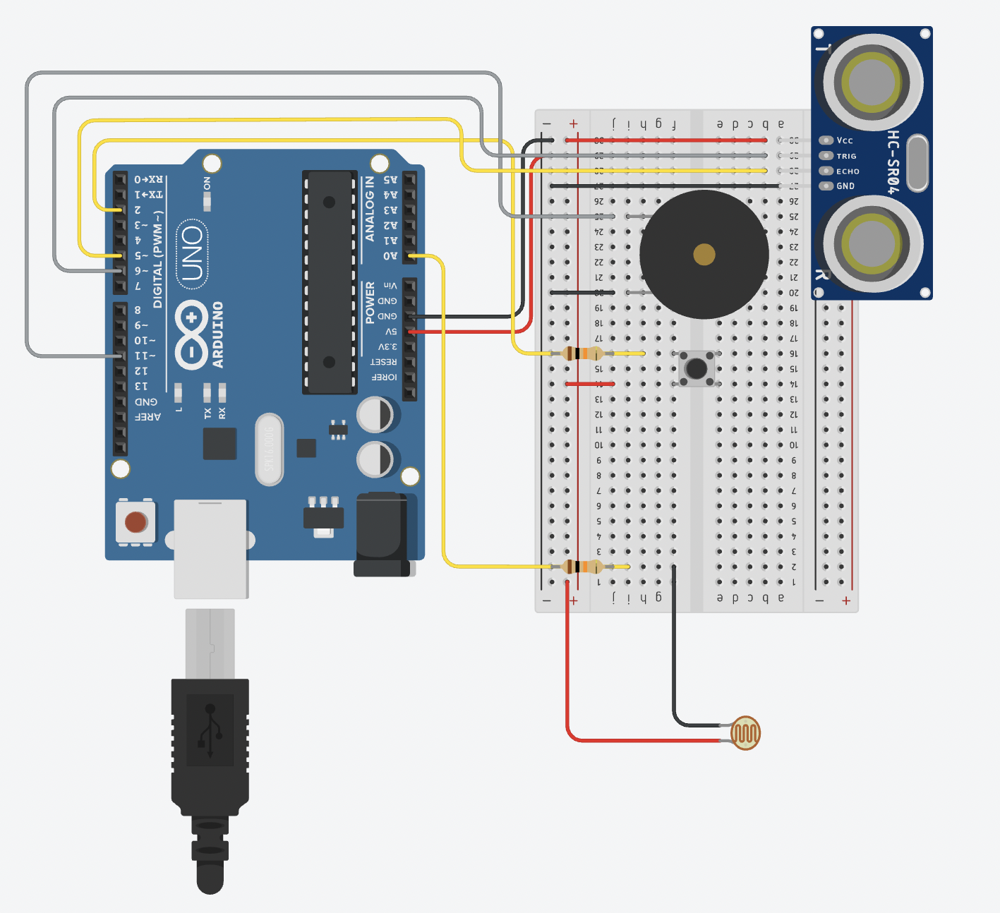
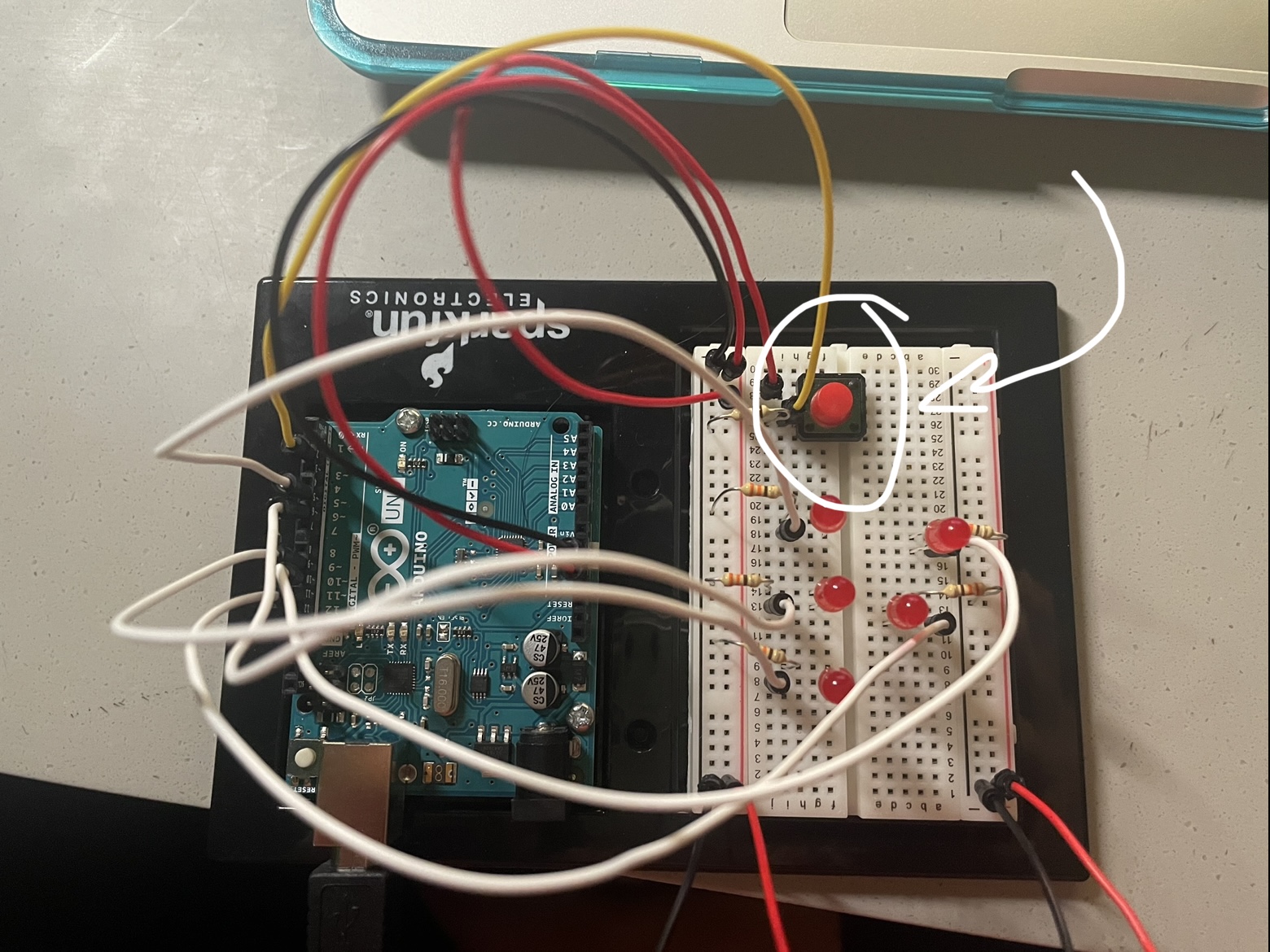
Flame Ears is an interactive artwork in which the user can play doctor and disease to patient Grace Benner, by turning on the lights with a push button and then either increasing the brightness of the ear flames (worsening the illness) or decreasing them (healing the patient) through the use of a potentiometer.
Idea:
I had a really hard time deciding what to do for this assignment, but I knew that something fire related would be interesting since in our fist lab, the LED blink reminded me of a fireplace for some strange reason. Inspiration hit me when I read an article about Grace Benner, a young women who was suffering from a mysterious illness. One of the symptoms of the disease was having red ears that were hot to the touch. Her symptoms came and went, which gave me the idea of using a drawing made about her condition and using LEDs to showcase the burning sensation that she had in her ears, allowing the audience to either worsen or better her situation.
Process:
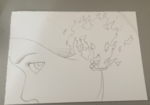
I started by making a sketch of the drawing.
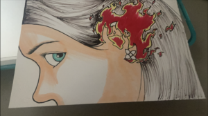
After I finished the sketch, I went on to ink and color the drawing.
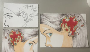
I then proceeded to place the image on the breadboard to see at which position I should locate the LEDs. Unfortunately, I noticed that the drawing was too big for such as small breadboard and even if I managed to light up the ear, the LEDs would be too far apart to create the “fire” effect I wanted. I thus made a smaller version of the drawing. It would fit perfectly, but then I realized that the cables would interfere since most of the drawing would be positioned towards the left (where the wires would fall). I thus decided to make another drawing that was the mirror of the original image and the size of the smaller version.
Once this was done, it was time to start the fun part: wiring the whole thing.
I placed the drawing on the breadboard and calculated where each LED had to be to illuminate the ear properly.
I tested the position by lighting up the LEDs.
Afterwards, I added a button and created the code to make the LEDs light up when the button was pressed.
Then I went in with a potentiometer. I tried two versions to use the potentiometer as a way to control the LEDs: the first was by using it to control the delay of the blinking of the LEDs (would create a delay between when one LED turns on and the next). It looked good, but would only work for one LED at a time which didn’t yield the effect I was looking for. I ended up using the potentiometer as a way to control the brightness and the delay so as to create a fire effect. Note: the way I tested the potentiometer was without the button. This is how it looked:
I then merged the code for the potentiometer and the one for the button to be able to turn on and off the circuit and if on, control the brightness of the LEDs.
I then started to think how to position things in the best way possible so as to not make the user experience uncomfortable because of the location of the circuit elements. For instance, I tried to put the button and the potentiometer in a series to reduce the amount of wires. It didn’t work.
I also ended up changing the position of the potentiometer since the original way made it awkward for the person to move the knob. I also clipped the wires together and toss them at the sides to get them out of the way for the drawing to fit.
Since I can’t record without one of my two hands, I made a stand for the painting out of a cup
Challenges:
Coding the “fire” effect. As you will see in my code, I tried various things to make it work. Also merging the potentiometer and the button required some thought, luckily, I including an analog in my initial trial with the button, so I had an idea of where to place the lines regarding the potentiometer.
Figuring out where everything should be was also very troublesome and required a lot of trial and error.
Recording with one hand while moving the know with the other
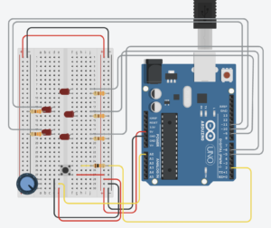
Circuit:
Note: in my actual circuit, I used white jumper wires for the OUTPUT of the LEDs, but that’s not the most visible color on TinkerCad so I assigned it the color gray.
Final Result:
Code:
// write the Arduino pin number of the LED
int ledPins[5] = {5, 6, 9, 10, 11};
int numLeds = 5;

//write the Arduino pin of the button, the state (off)
int buttonPin = 2;
bool onOff = false;
//and set a variable to hold the previous state to off
bool previousButtonState = false;

//write  the Arduino pin of the pontentiometer, its initial value
int potentiometerPin = A0;
int potentiometerValue = 0;

//create a variable for the brightness of the pins
int brightness = 0;

void setup() {

  //set the mode  of the leds to Output
  for (int i = 0; i < numLeds; i++)
  {
    pinMode(ledPins[i], OUTPUT);
  }
  //set the button as Input
  pinMode(buttonPin, INPUT);
}

void loop() {
  //read if the button has been pressed
  int buttonState = digitalRead(buttonPin);

  //change onOff if there is a change in the button state
  if (buttonState == HIGH && previousButtonState == LOW)
  {
    //onOff becomes the opposite of what it currently is
    onOff = !onOff;
  }

  //Serial.println(buttonState);

  //if the circuit is on
  if (onOff)
  {
    //read the value that the potentiometer is giving
    potentiometerValue = analogRead( potentiometerPin);

    //map the input of the potentiometer to values within the LED brightness spectrum
    brightness = map(potentiometerValue, 0, 1023, 0, 255);

    //for all the LEDs in the circuit,
    for (int i = 0; i < numLeds; i++)
    {
      //turn on the led with a certain brightness
      analogWrite(ledPins[i], random(brightness));

      //originally I used random(200), but I found brightness to give me a better effect
      delay(random(brightness)/2);
      //this is what gives the lights the "fire" effect

      //Original Version of the fire effect
      //I used analog but without the input of the potentiometer to test if the "fire effect" works
      //analogWrite(ledPins[i], random(130) + 125);
      //delay(random(100));
    }
  }
  //if the circuit is off
  else
  {
    //for all the LEDs
    for (int i = 0; i < numLeds; i++)
    {
      digitalWrite(ledPins[i], onOff);
    }
  }

  //assign the current button state as the previous before repeating the loop
  previousButtonState = buttonState;


  //Serial.println("onOff = " + onOff);
  //Serial.println("button State = " + buttonState);
  //Serial.println("previous  = " +  previousButtonState);


  //potentiometerValue = analogRead( potentiometerPin);
 // brightness = map(potentiometerValue, 0, 1023, 0, 255);

  //Trying Delay to give the 'treating' effect
  /*
    for (int i = 0; i < numLeds; i++)
    {
      digitalWrite(ledPins[i], onOff);

      digitalWrite(ledPins[i], HIGH);
      // stop the program for <sensorValue> milliseconds:
      delay(potentiometerValue);
      // turn the ledPin off:
      digitalWrite(ledPins[i], LOW);
      // stop the program for for <sensorValue> milliseconds:
      delay(potentiometerValue);


      analogWrite(ledPins[i], random(brightness));
      //originally I used random(200), but I found brightness to give me a better effect
      delay(random(brightness));

    }
  */
}
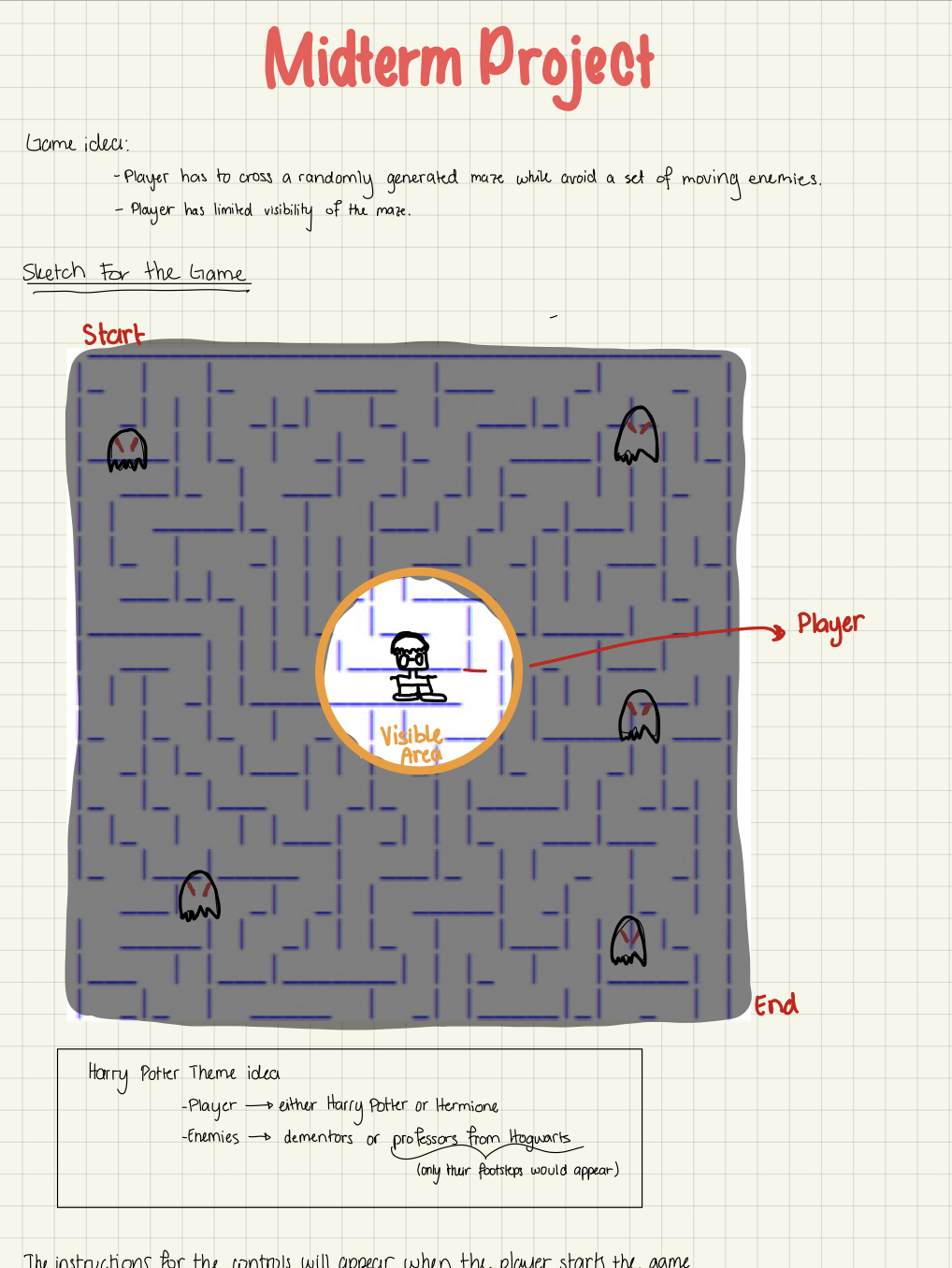
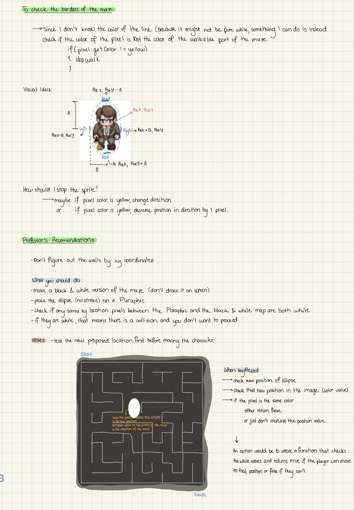
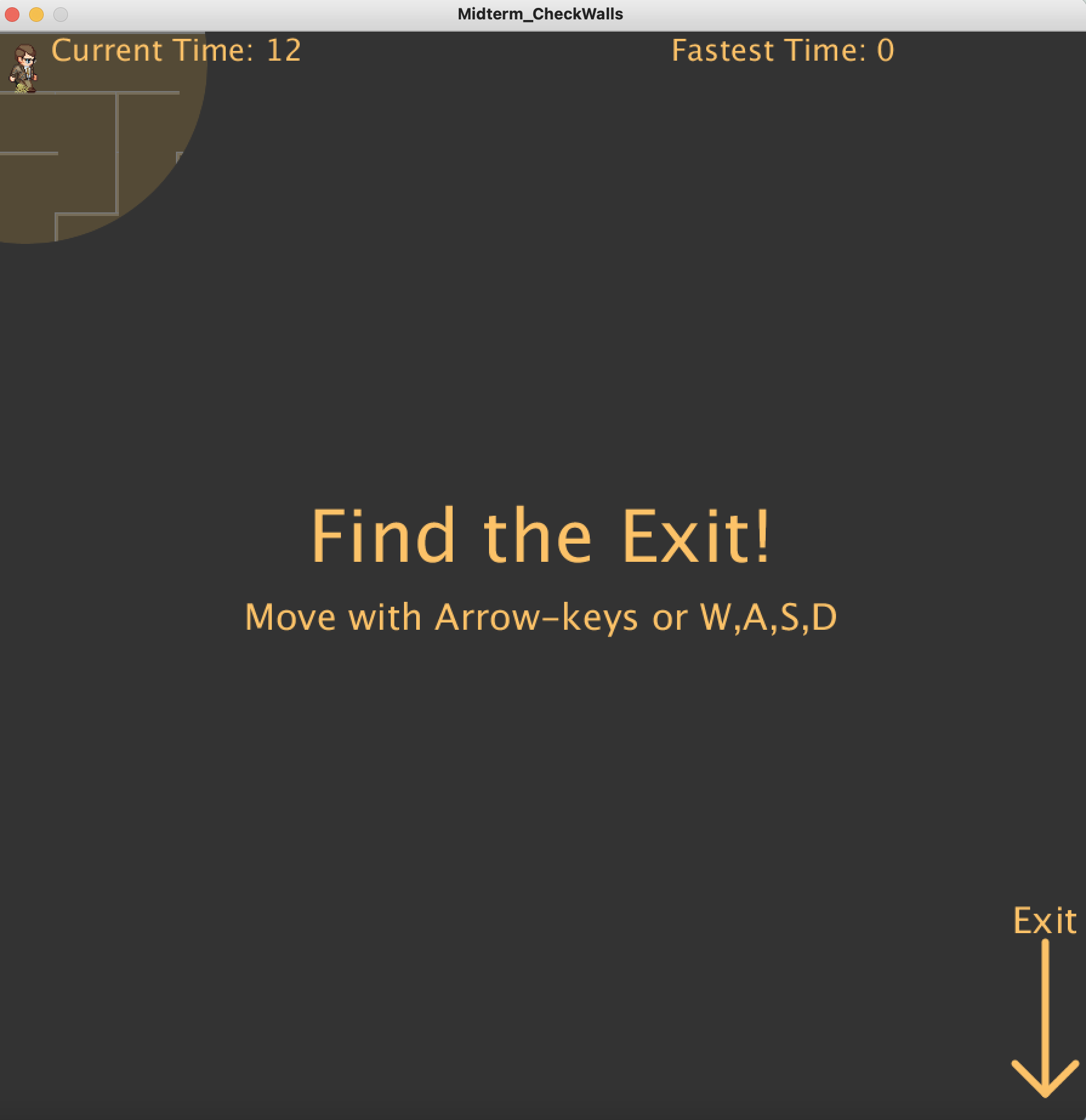
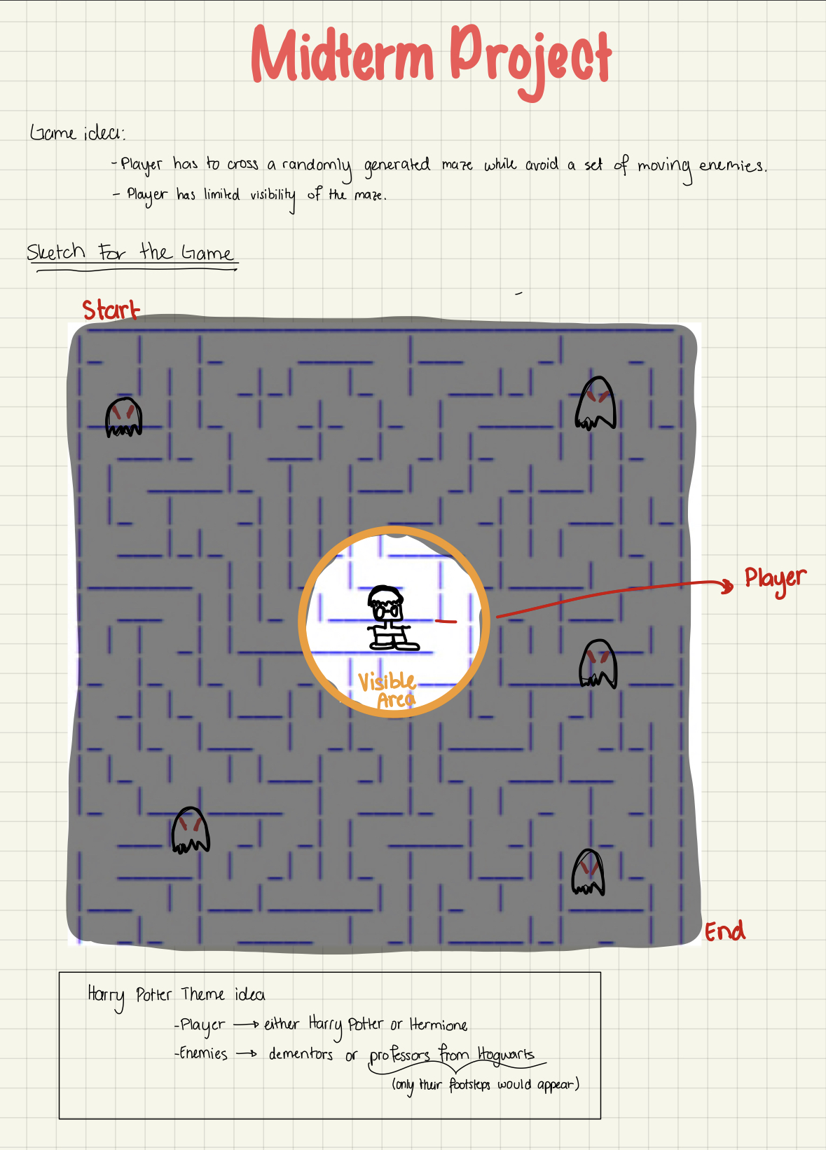
This game, inspired by the successful Harry Potter book series and the retro game PacMan, consists of discovering the exit of a labyrinth. During their journey, the player will have to overcome the dim light that illuminates their way, which becomes small each time the villainous dementors approach. The player will have to dodge this evil creatures if wants to reach the end of the maze and win the game
The development of the project of this video game was a process that went through a long path of challenges, difficulties and many hours( and entire days of work). Solving some of those setbacks led me to spend hours and hours watching tutorials, consulting with my teacher, others students and some tours of the buildings in search of answers and solutions that in the end were compensated by the satisfaction of seeing the finished product
Sneak Pic
(My laptop can’t record audio, but all the screens are accompanied by music from the Harry Potter series in the actual game.)
Thought Process:
Testing things:
I had a lot of issues testing things in my code, primarily because I have a lot of files, and eventually Processing ran out of memory so I had to delete some stuff in order for the program to run. Testing some functions could take up to 2 minutes to load. I am happy with how the project looks but not that much with its efficiency.
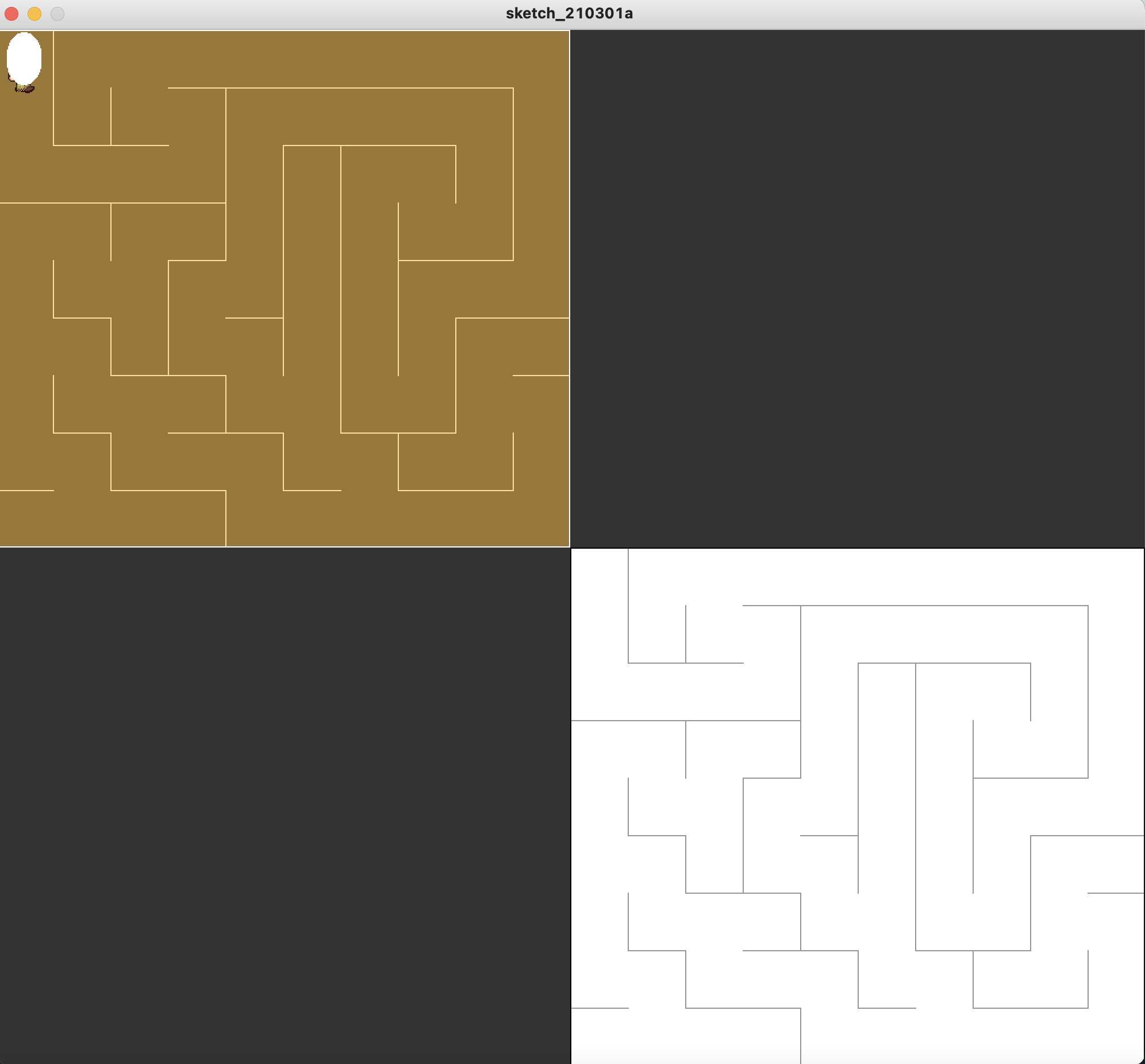
Testing copies of PGraphics
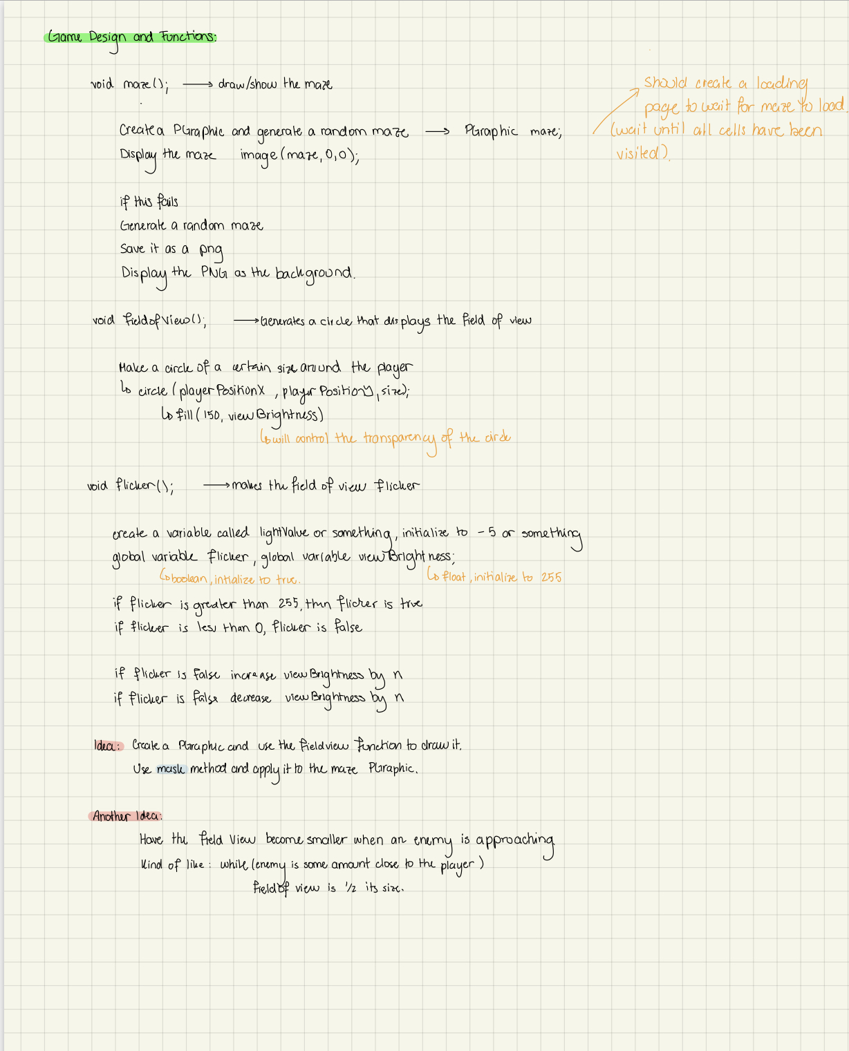
Testing Mask function
Testing the Flicker of the player’s field of view
Testing of the dementors (enemies)
First version of the Instructions
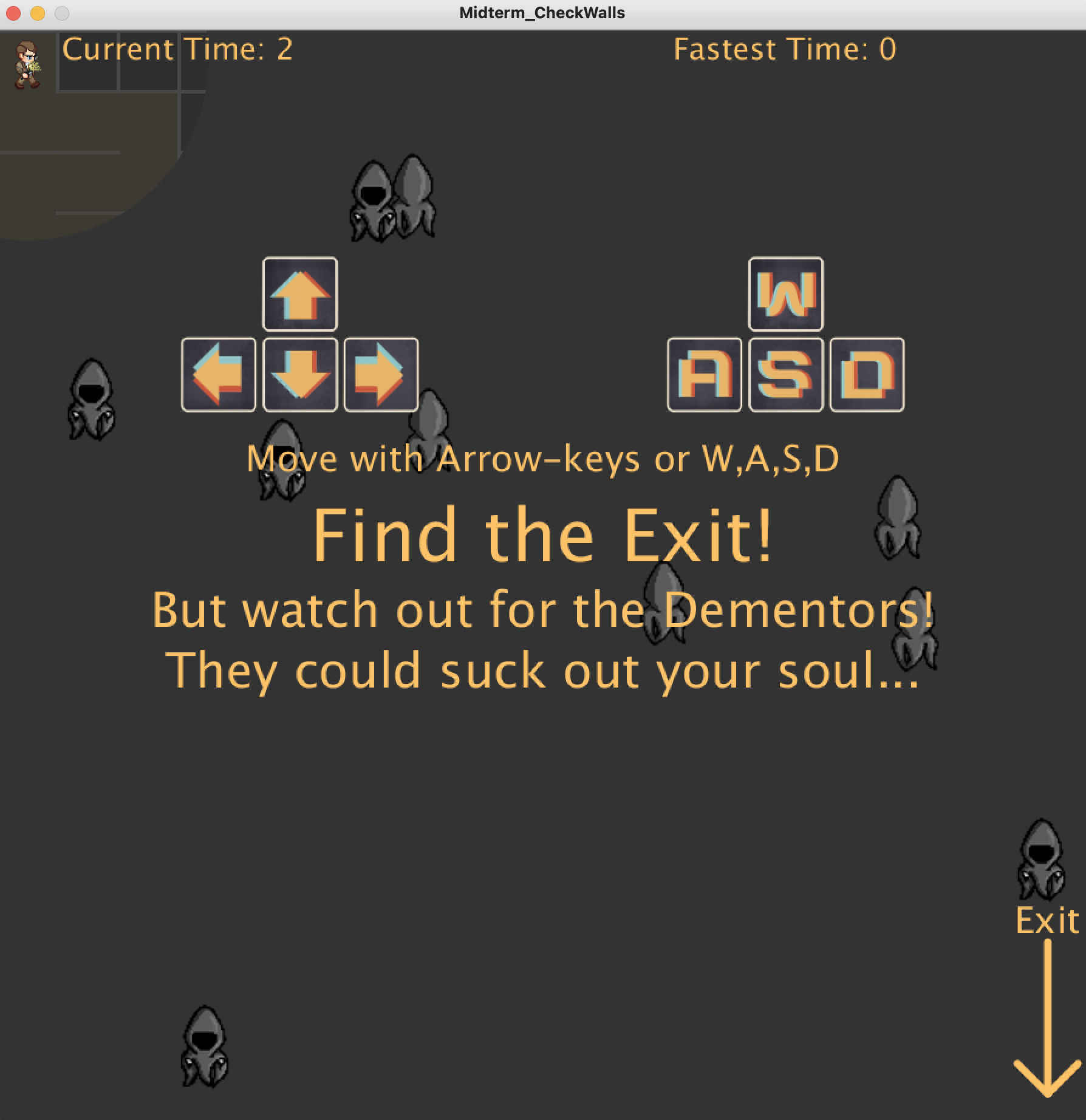
Final Version of the Instructions
Note: I drew all the UI, titles and Sprites for this project
Things I would Improve
I really want to add levels (hard mode, normal mode, easy mode, etc).
I also want to have different sets of enemies and maybe a final boss (Voldermort?).
I hope you guys enjoy this game. I put a lot of effort in it and am really happy to share it with you.
The idea for my game is to have a player cross a maze in which they will have to avoid a number of enemies. The player will have a limit visibility of the maze (delimited by a circle around the player character). The player will be able, however, to see the position of the enemies (at least that is the idea). It is kind of a PacMan inspired game but with a twist, you could say.
Here is a rough sketch of how the game will look (kind of):
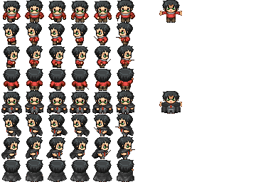
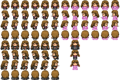
I also very recently came up with the idea to set a theme for the game (I am creating my own sprites so I needed inspiration). Up until now, I have settled for a Harry Potter theme (I have a friend who is obsessed with Harry Potter) because I found these sprites on internet while I was looking for examples and they reminded me of it.
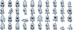
These are the sprites:
The following made me think about the dementors in the series.
Progress:
For this week I decided to focus on creating the maze (more specifically, been able to generate random mazes) and on going through the PGraphics library. I went through the documentation some online tutorials to better understand how to use it.
Note: the fact that I wrote that I decided to focus on these things means that I actually took a long time to understand PGraphics and even more on creating the code to generate the maze.
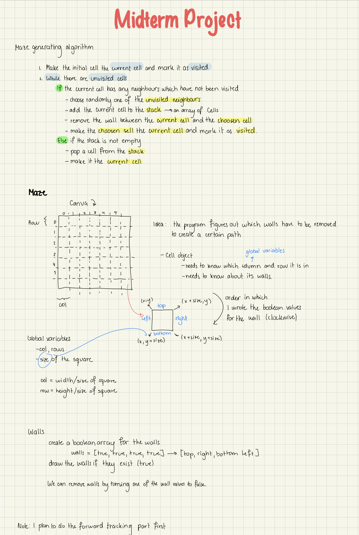
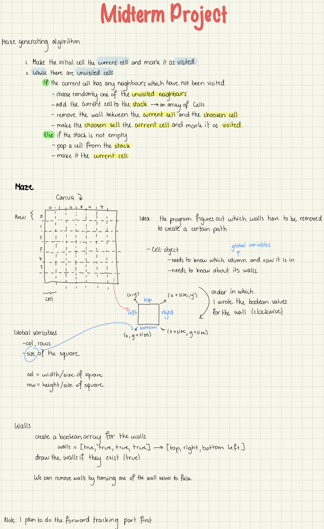
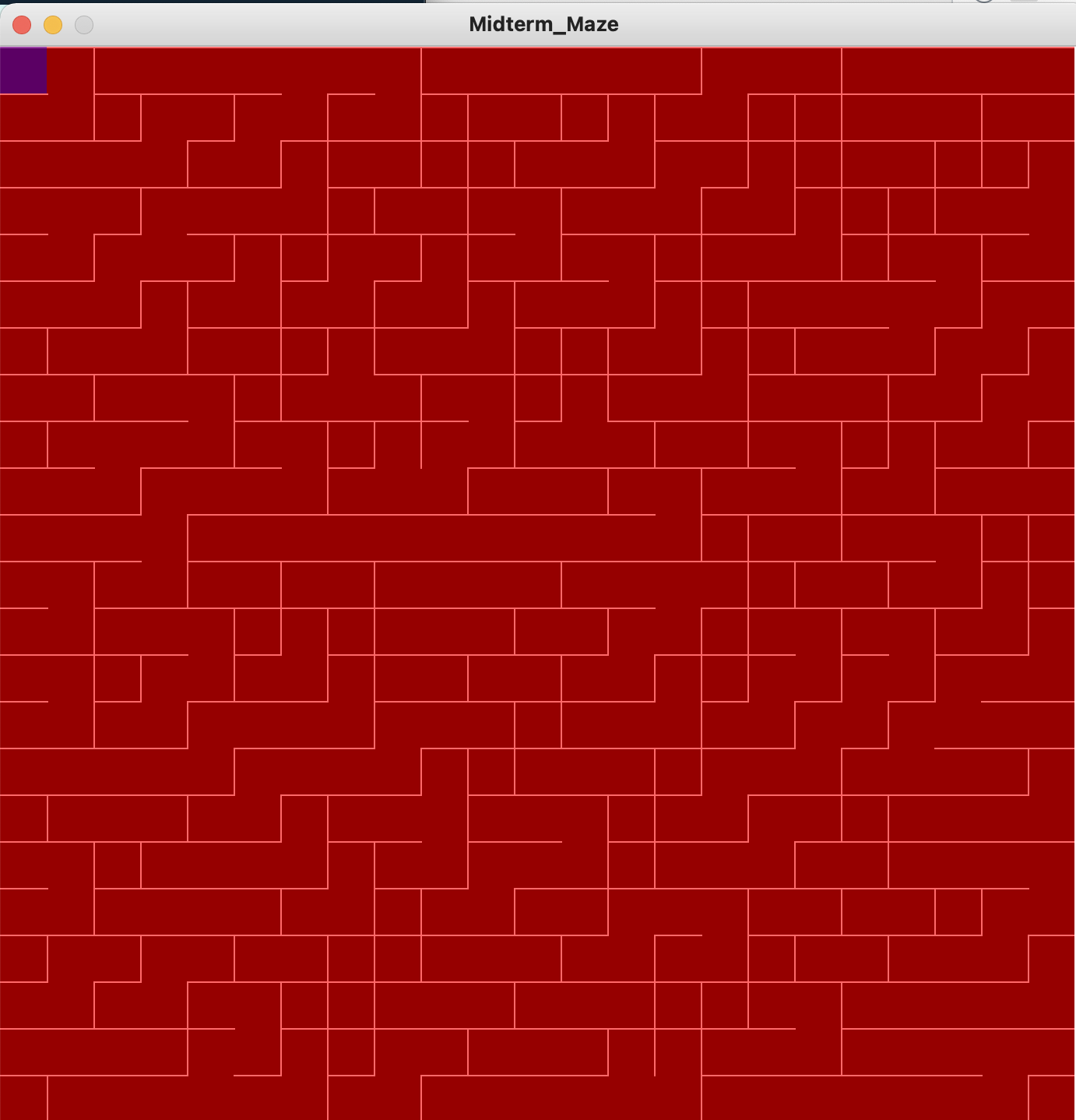
To create the maze, I decided to create a grid with cells. The program starts at the upper left cell. It checks for neighboring cells and selects a non-visited cell (one the program has not gone through) and removes a wall (line of the grid). Then it moves to that cell and checks for neighbor cells: the process repeats until a path has been formed. Then the program fills in the left out non-visited cells and randomly removes a wall from them to make them look like a maze. The program is recursive so the last position will be that at the beginning of the maze.
The following is a description of my thought process along with the written algorithm (taken from Wikipedia , there are a lot of options to choose from there).
I had a lot of problems writing the code.
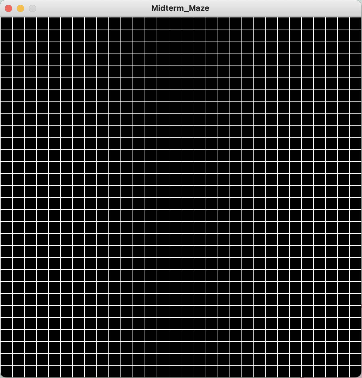
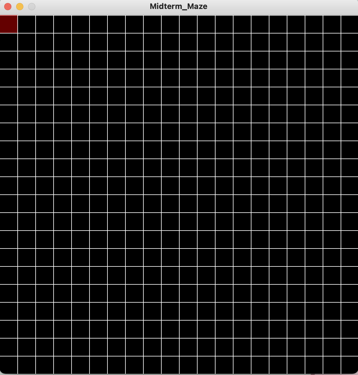
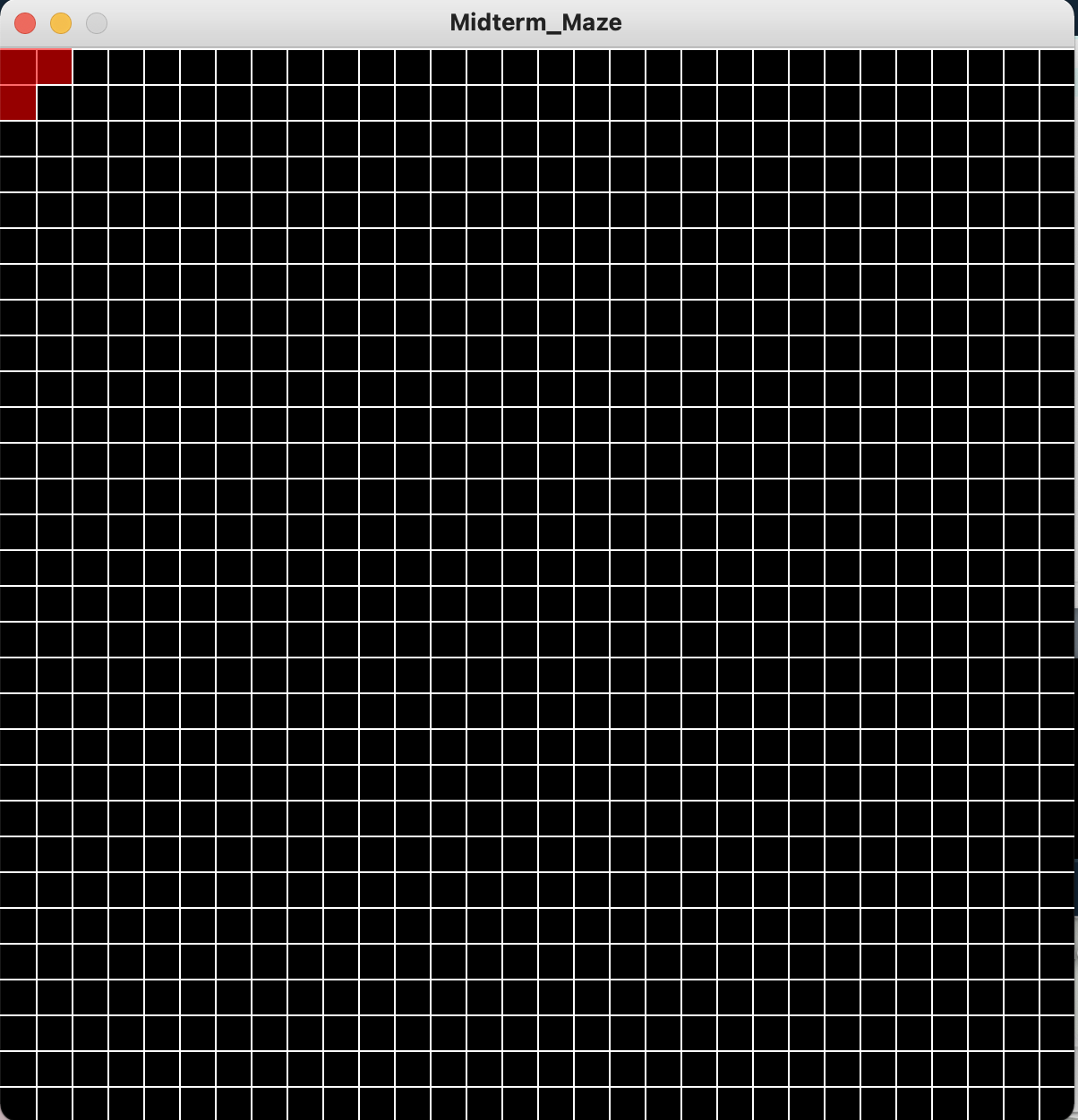
At the beginning it was ok. I manage to create a grid and to be able to place in a different color the visited cell.
The problem came when we started to check the neighboring cells. The problem was the edges: sometimes the program will run well and would move to the neighbor cell, however, when the current cell was an edge, sometimes it choose a neighboring cell outside the canvas, so I had to write a case for that.
This is how it would look:
It was also quite hard to figure out how to assign the cells to certain variable (there was a lot of sketching and thinking involved behind that and it took a lot of time to figure out just how to show and remove the walls).
In many cases, what generate was something that did kind of look like a maze but that had no solution.
For example:
The problems where almost always associated with logic with what wall I was telling the program to remove. I watched some YouTube videos regarding maze generation to see how they removed the walls (all of them were in other programming languages, but the pseudocode was all I really needed to start fixing this mess).
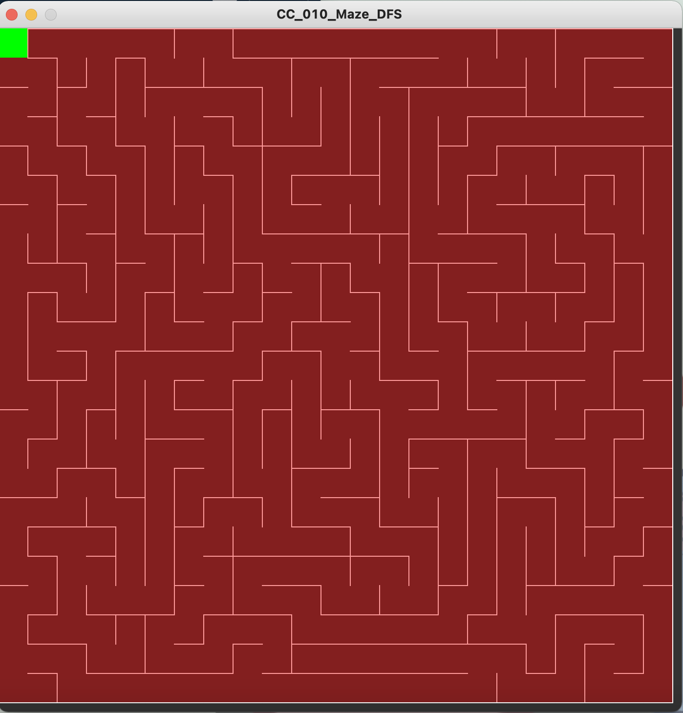
After much struggling, yesterday I was finally able to generate a maze.
However in the morning, something happened (I think I might have erased something by accident). My code wasn’t working anymore.
After smashing my head against the wall all morning on my birthday because I couldn’t figure what was wrong, Professor Aaron illuminated me by asking with which function the cell was moving. I had accidentally erased the part in which the cell moved to the next to create a new path, and I completely missed it. Perhaps I’ve been staring at this code for so long that my mind was just assuming that it was there, because I swear, the fact that that part of the code was missing just completely went over my head.
I know have a code that works, 7amdullah!
This is the final result (also, yes, I keep switching colors and size because I wasn’t sure about which would look good, but now I decided for the theme of Harry Potter, I settled for this yellow color. Hopefully I won’t change it again).
Code:
Main Tab
int cols, rows;
int cellSize = 50;

ArrayList<Cell> grid = new ArrayList<Cell>();

Cell currentCell;

ArrayList<Cell> stack = new ArrayList<Cell>();

void setup()
{
  size(900, 900);
  //fullScreen();

  cols = floor(width/cellSize);
  rows = floor(height/cellSize);

  //create Cell objects and add them to array list
  for (int j = 0; j < rows; j++)
  {
    for (int i = 0; i < cols; i++)
    {
      Cell newCell = new Cell(i, j);
      grid.add(newCell);
    }
  }
  //start the path at grid 0
  currentCell = grid.get(0);
}

void draw()
{
  background(51);

  //check that the grid displays correctly
  for (int i = 0; i < grid.size(); i++)
  {
    //I made the mistake of writing grid.length() instead of grid.size()
    grid.get(i).show();
  }

  currentCell.visited = true;
  currentCell.highlight();
  //currentCell.checkAdjacentCells();

  // STEP 1
  Cell nextCell = currentCell.checkAdjacentCells();
  if (nextCell != null)
  {
    nextCell.visited = true;

    // STEP 2
    stack.add(currentCell);

    //STEP 3: remove the walls
    removeWalls(currentCell, nextCell);

    // STEP 4
    currentCell = nextCell;
  }

  //this is what corrected the problem with the null value
  else if (stack.size() > 0)
  {
    currentCell = stack.remove(stack.size()-1);
  }
}

void removeWalls(Cell current, Cell next)
{

  int x = current.i - next.i;

  if (x == 1)
  {
    //remove left wall
    current.walls[3] = false;
    //remove right wall
    next.walls[1] = false;
  } else if (x == -1)
  {
    //remove left wall
    current.walls[1] = false;
    //remove right wall
    next.walls[3] = false;
  }

  int y = current.j - next.j;

  if (y == 1)
  {
    //remove bottom wall
    current.walls[0] = false;
    //remove top wall
    next.walls[2] = false;
  } else if (y == -1)
  {
    //remove top wall
    current.walls[2] = false;
    //remove bottom wall
    next.walls[0] = false;
  }
}
Cell Object
class Cell {
  int i, j;

  //order of the walls is top, right, bottom, left
  //this will allow us to remove walls in the grid
  boolean[] walls = {true, true, true, true};
  boolean visited = false;

  Cell(int indexI, int indexJ) {
    i = indexI;
    j = indexJ;
  }

  int index(int i, int j)
  {
    //return 0 for edge cases
    if (i < 0 || j < 0 || i > cols-1 || j > rows-1)
    {
      return 0;
    }

    //formula to calculate index (same as the one to calculate pixels)
    int index = i + j * cols;
    return index;
  }
  Cell checkAdjacentCells() {
    ArrayList<Cell> adjacentCells = new ArrayList<Cell>();

    //get the cells adjacent to the cell the program is currently at
    Cell top    = grid.get(index(i, j-1));
    Cell right  = grid.get(index(i+1, j));
    Cell bottom = grid.get(index(i, j+1));
    Cell left   = grid.get(index(i-1, j));

    if (top != null && !top.visited) {
      adjacentCells.add(top);
    }
    if (right != null && !right.visited) {
      adjacentCells.add(right);
    }
    if (bottom != null && !bottom.visited) {
      adjacentCells.add(bottom);
    }
    if (left != null && !left.visited) {
      adjacentCells.add(left);
    }

    if (adjacentCells.size() > 0) {
      int r = floor(random(0, adjacentCells.size()));
      return adjacentCells.get(r);
    } else
    {
      return null;
    }
  }

  void highlight() {
    int x = i*cellSize;
    int y = j*cellSize;
    noStroke();
    fill(0, 255, 0);
    rect(x, y, cellSize, cellSize);
  }


  void show() {
    int x = i*cellSize;
    int y = j*cellSize;
    stroke(255);

    //if the walls are defined
    if (walls[0])
    {
      line(x, y, x + cellSize, y);
    }
    if (walls[1])
    {
      line(x + cellSize, y, x + cellSize, y + cellSize);
    }
    if (walls[2])
    {
      line(x + cellSize, y + cellSize, x, y + cellSize);
    }
    if (walls[3])
    {
      line(x, y + cellSize, x, y);
    }

    //line(x           , y           , x + cellSize, y);
    //line(x + cellSize, y           , x + cellSize, y + cellSize);
    //line(x + cellSize, y + cellSize, x           , y + cellSize);
    //line(x           , y           , x+ cellSize , y);

    //noFill();
    //rect(x, y, cellSize, cellSize);

    //change color of a cell if it has been visited
    if (visited)
    {
      noStroke();
      fill(255, 204, 102, 150);
      rect(x, y, cellSize, cellSize);
    }
  }
}
*Trigger warning: as you can see by the title, I walk about deaths of women in my home country and describe the femicide that inspired me to work on this project under the Inspiration section*
Description:
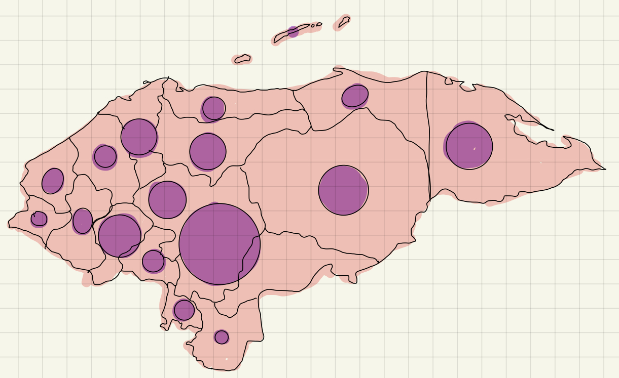
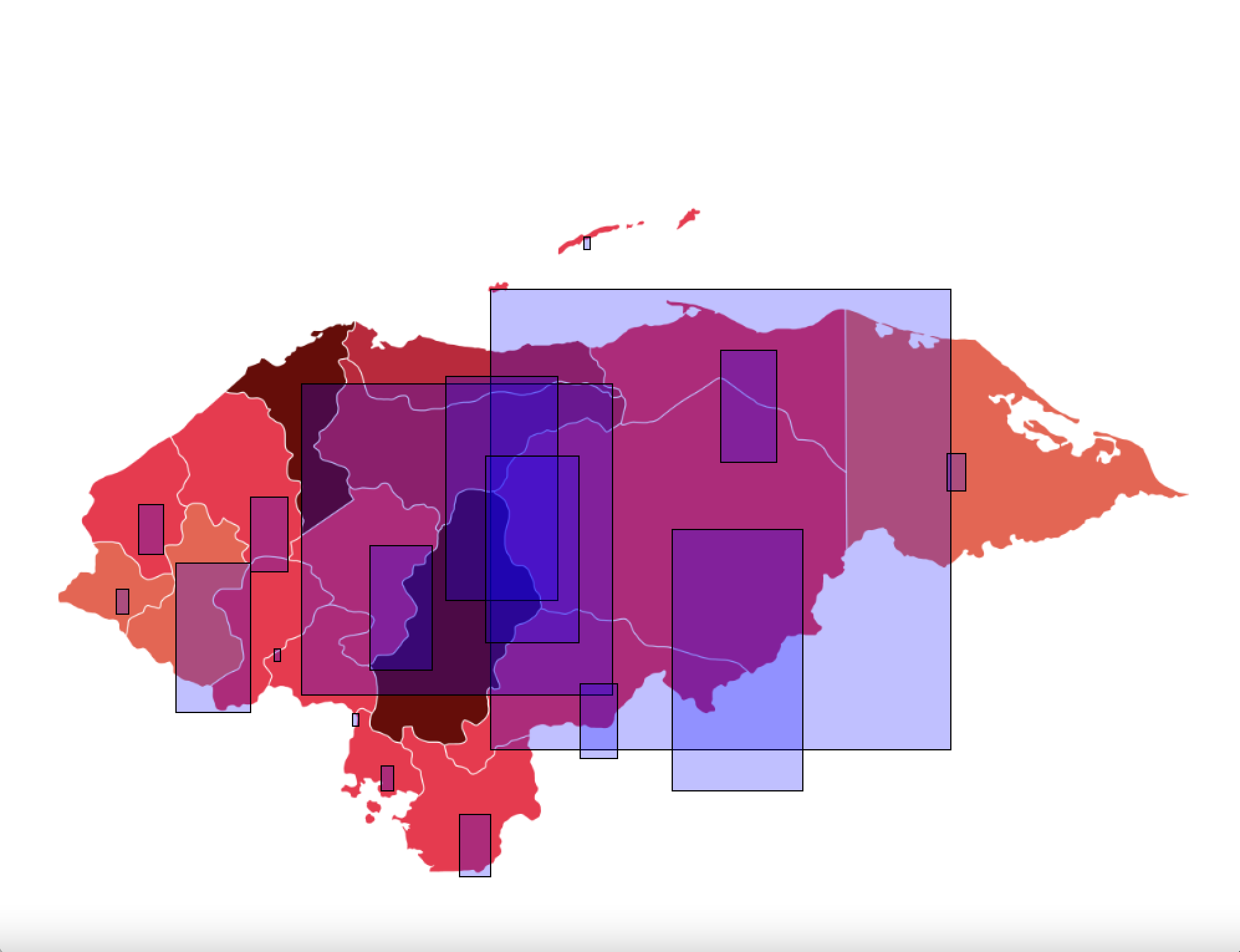
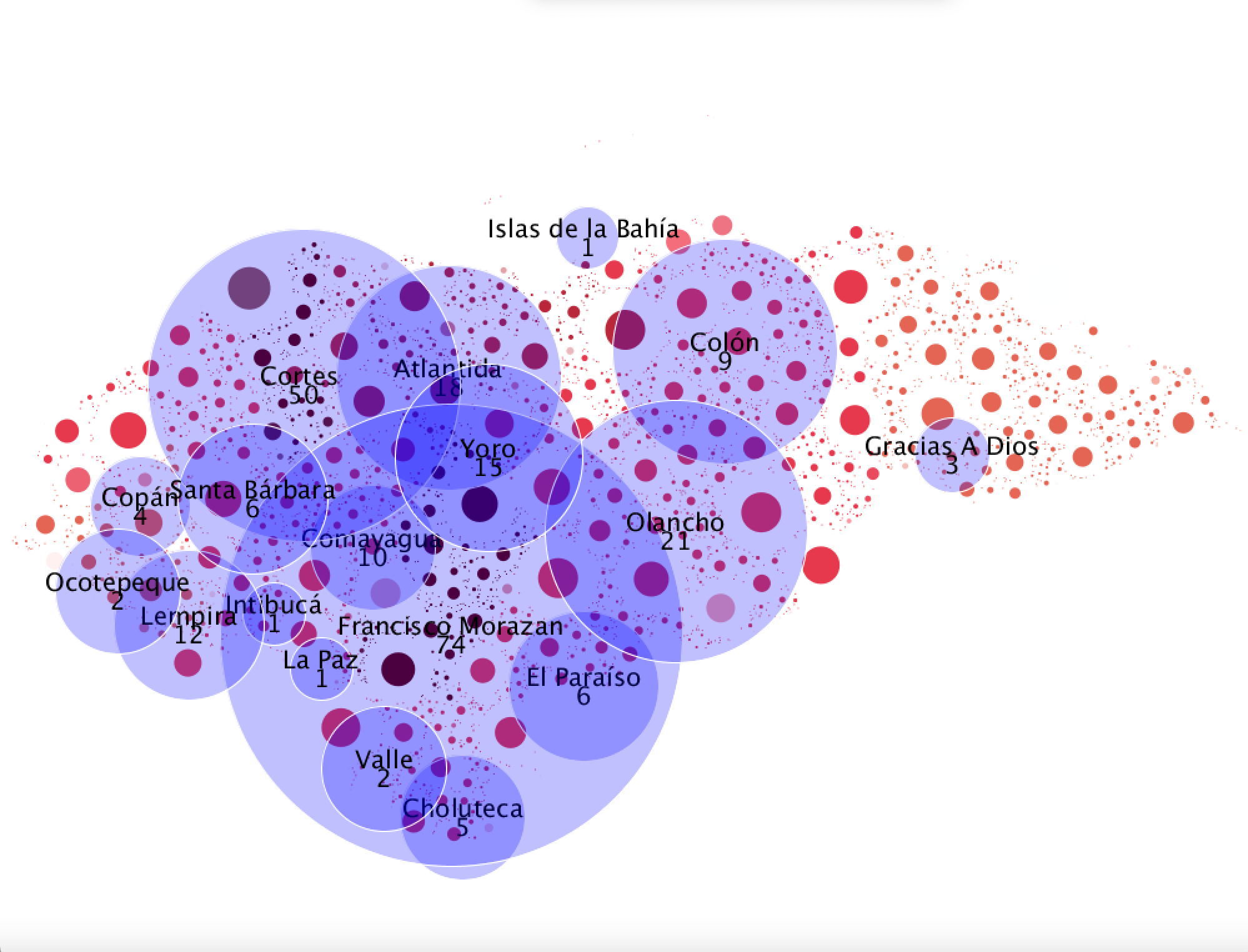
This is a project that showcases the number of femicides committed in the country of Honduras since January 2021. It displays the number of cases by department (Honduran word for state) and the user can place the mouse on top of the bubbles containing the numbers to look at the name of the department. Meanwhile, the map of Honduras can be seen forming in the background, with the bubbles placed on their respective location in the map.
Inspiration:
To be honest, my original idea was to make something using generative text, however, I felt like I understood generative text better than I did data visualization, so I decided to make the project based on data visualization to practice more. The idea of displaying the number of femicides committed in Honduras, my country since the start of 2020 came from I post I saw last week about a girl who was detained by the police at night and was discovered dead in her cell (most likely because she resisted an attempt to sexual assault by the policemen who imprisoned her). The police took her to the hospital already dead, but filed in the report that she was taken alive and died while the doctors treated her and they refused to perform an autopsy, dismissing the case as a suicide attempt. The hospital, however, released their report in which they explained that she was strangled (most likely by men). Because of how boldly the police died, many people in the town where this happened started to make a campaign that grew into a social media under the hashtag JusticeForKeyla (the name of the girl). Nevertheless, though the police has acknowledged that Keyla didn’t commit suicide, they refused to investigate. The policemen who incarcerated Keyla have been re-assign and their whereabouts are not known.
I was outraged by this case, not only because it was the police, the people charged with the safety of citizens, the ones who killed her but also by the fact that they lied to openly about it. Femicide, unfortunately, is not something uncommon in my country and cases like Keyla’s are some of the few that are actually been investigated, if not by the police, by the Honduran people. It is very dangerous to be a women in Honduras and in honor of the 90% of the victims that will not receive justice for their murder, I decided to make this visualization.
Process:
I had no idea how to start the project. I knew what I wanted it to look like and I had the data of the femicides this year from one of the NGO’s back home that advocates for women’s rights., but I didn’t know how to come up with the logic to actually write the code. I decided to make a sketch of how I wanted the visualization to look like to get my ideas in order.
This is what I came up with:
After doing the sketch, I decided to first get the locations of the coordinates in which to place the circles. I did this mainly using trial and error and the mouseX, mouseY . I also tried experimenting with other shapes. The rectangle was a good contender, but I preferred the overall look of the circles.
This is what they looked like:
Once I had the locations, I added them to the data set containing the # of deaths.
Afterwards, I decided to stop hardcoding and get to work with the Table object. This took quite some time as I didn’t really understand how to read the rows of the table that well. Thus, I went to Baba Daniel Shiffman for help and watch a lot of his videos on Tabular Data in Processing.It was a great resource and after following along his examples, I manage to grasp a fair amount of the knowledge needed to proceed. (He also gave me the idea of using a hover so the user could see the number of deaths and the department, which I tried with the original ‘hardcoded’ version).
The difficult part came when doing the objects. I found it very difficult to make the bubbles look like I wanted them to, since there were departments that had 74 to 50 deaths in January, contrasting with other departments that had only 1 or 2 deaths (which are mainly the inhabited territories ), thus I couldn’t use the same scale for make all the circles since one would look too big while the others too small. I opted for having different scaling values for the radius of the bubbles depending on the magnitude of the number of deaths .
Afterwards, I remember look at my visualization thinking that it looked pretty good regardless of the fact that every 30 minutes I edited something I completely crashed the program. But alas, the main product was finalized. I still wanted to do something more with the background because I wanted more circles in the sketch. I read through some of my class notes and remembered that I have never used ArrayList<>; . I then Googled ideas to practice using ArrayList<>; and someone in a forum mentioned making a background out of digital circles using. I then binged watch for two days how to use ArrayList<>; and did some pretty lame attempts at it, but once I manage to understand what I was doing, I decided to make a background since the map I was using was a transparent png . It look fine, but a little overwhelming because of all the color.
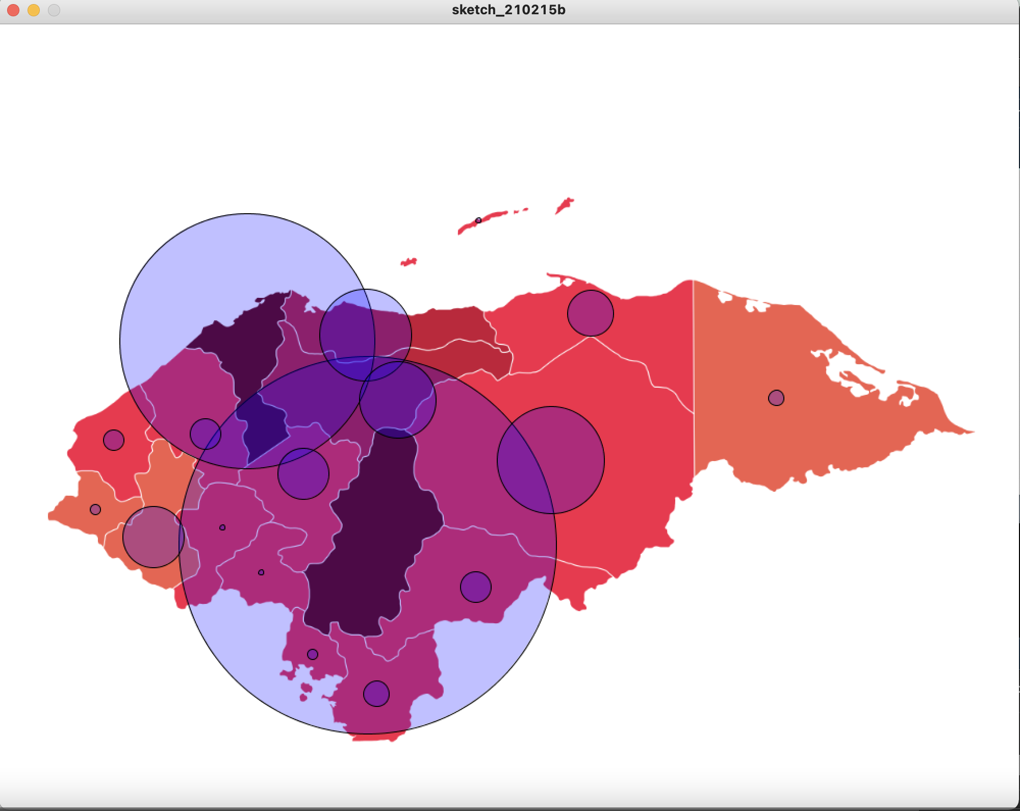
When that was done, I decided to experiment a little with the things we learned last lecture about pixels and took the color values of the pixels in the image I had for the map of Honduras to determine the color of the circles that would comprise the more dynamic map. That created some very interesting results (and also a lot of bugs).
This is what one of my final sketched looked like. Then, I recalled that I had forgotten to add the hover function for this ‘final’ version of the sketch, but since I had resized the bubbles, some of the smaller ones where not hovering correctly. Figuring out why my logic was wrong took a lot of time, but at the end it was a silly mistake of not including the scale variable in the radius to calculate the distance between the mouse and the center of the bubble.
Finally, I began to toy around with the colors of the background because I was creating circles for all of the canvas, so the circles outside the map would be white and thus wouldn’t show on the screen. I wanted to see if I could use this circles to make the sketch nicer and a black background provided a very nice contrast. I also decided to add more space between the circles because I thought that the visualization looked better with the spaces. The most interesting thing is that since the circles are created randomly, when I run the program it looks different (even if it is very slightly) every time.
This is the final result
Difficulties:
I already mentioned some in the project description, but my main difficulties were:
Making sure that the Table set loaded correctly and under its respective variable.
Finding the x and y locations where the bubbles needed to be. It wasn’t necessarily hard, but it was very time consuming and such a pain.
Figuring out the logic to create objects using the Table (this took a lot of Google and many tutorials).
Trying not to get confused about what I was editing in the main function since it is quite long. (I gave up and decided to make functions for each step and then call those functions in the setup() and the draw() ).
Making the bubbles look good.
Learning how to use ArrayList. I don’t know why but this was very hard for me to grasp, specially how to compare values of different elements within the array list (the whole for(class object: objectList) thing).
The circles for the map where very hard. It took a lot of my time just to figure out how to detect if they touched another circle or not.
I named a variable expand() and it wasn’t working correctly because Processing has an inbuilt function called expand() that I wasn’t aware of.
I had to add a variable called attempts to control the main loop that loads the map because I read in a forum that if you don’t do it, then you will have an infinite loop and that is bad.
Figuring out what was wrong with the hover because it wasn’t working after resizing the bubbles.
SO. MUCH. DEBUGGING (I’m gonna become an exterminator)
Conclusion:
A good chunk of my time for this project was watching and reading tutorials about how to do things. I think it was beneficial in the sense that, I didn’t feel completely lost about what alternatives to try, but it also frustrated me a lot when I thought I was doing everything right but then I made a very small and silly mistake that kept me up at night.
Overall, I liked this project. It was very personal and I think that helped me keep on working regardless of how often stuff didn’t work.
This is the link to my GitHub because the coded is somewhat long and I already took a lot of space with my explanation.
In this simple game, the player controls a spacecraft whose mission is to collect StarBits, however, they must avoid colliding with meteors or they will risk loosing all the progress they have made. Score is displayed on the upper left corner. When the player collides with a meteor, the spaceship becomes red for a while and the score keeps decreasing until they get out of the way of the meteor.
Idea
I got inspiration from one of Daniel Shiffman’s Coding Challenges titled Starfield and from Super Mario Galaxy in which Mario collects this star shaped things called Starbits.
Process
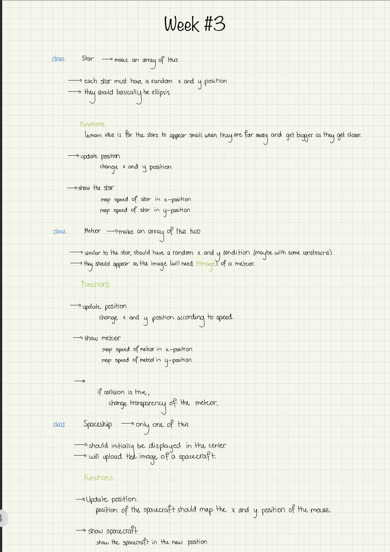
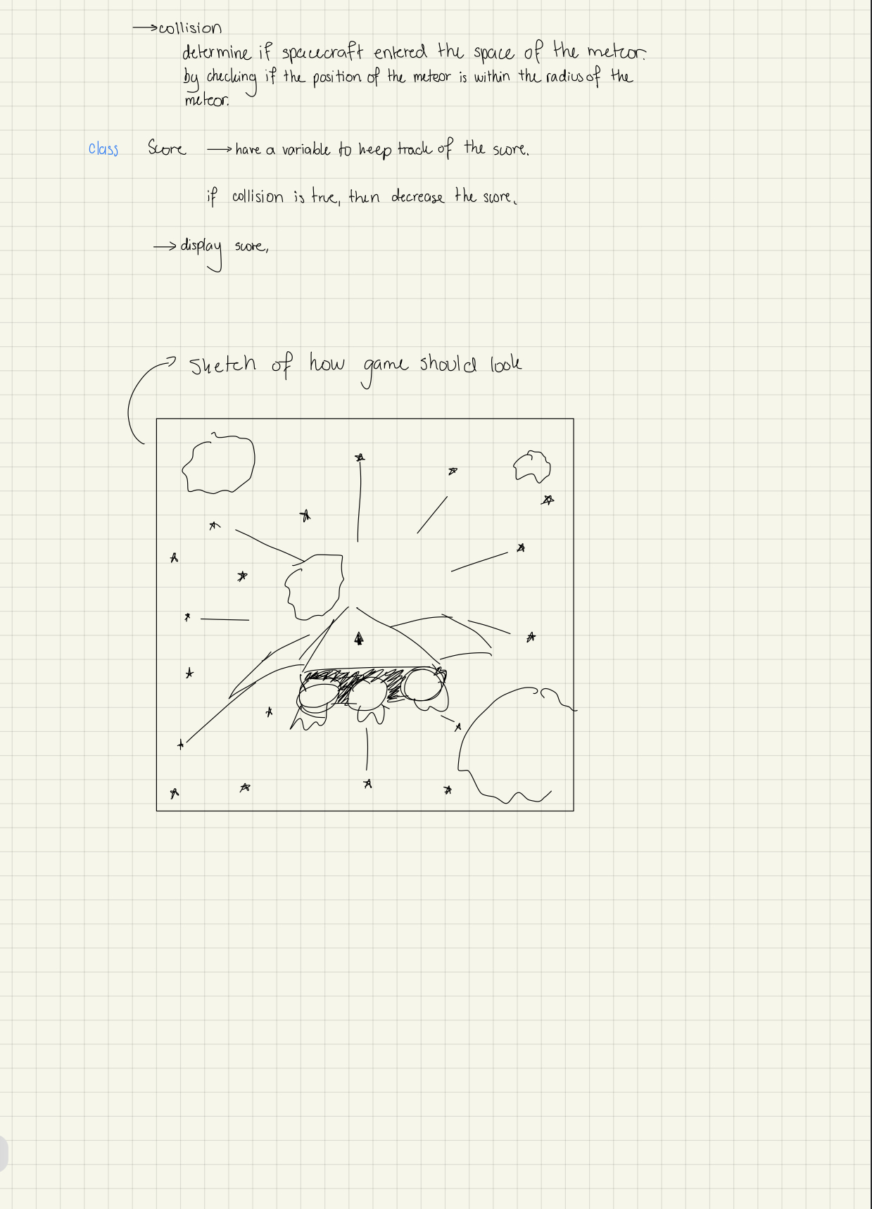
After watching the video and playing a little of Mario Galaxy with a friend, I decided to write down the classes and functions that I thought I would need for this assignment. I did this mainly because last assignment was very chaotic for me in terms of knowing what I needed to do, so I decided to write how I was thinking of making the code rather than just go at it.
This is what I ended up with:
I decided to star with the background and do the star object first because I thought that after watching the video, I could do it in a breeze, after all Shiffman’s video is 13 minutes.
I took a whole day to figure out how to do just the background. Also, the field that I was making only appeared on the lower right hand corner. Like this:
So I texted on the Discord chat and Professor Shiloh and Professor Aaron came up with a solution, thank God.
Anyways, moving on.
After doing the Stars, I proceeded to make the spaceship. I did two versions of it: one controlled with the keyboard and one with the mouse. I wasn’t sure which one to leave because I felt like they had a different range of motion and deciding would rely on how the meteors and starbits.
Once the controls for the spaceship were done and the image of it was resized, I decided to make the meteors.
(Just a side note: I know that I am actually doing meteroids and not meteors, but meteors is just easier on my poor brain).
I think this was the hardest part of the process. The meteors were just not cooperating with me. When they were immobile and I just placed them at random positions, they looked beautiful, but then, when I started to make the functions to move them, it was just horrible. My idea was to do a similar mechanic to the stars and increase the meteor’s sizes as it moved through the screen. Nonetheless, when I tried to resize it, the more time I left it moving, the blurrier the image got.
Like this:
After spending almost a day in useless attempts to better this, I decided to text on the Discord group and professor Aaron recommended using the scale() function along with changing the values I used to map the size of the meteor.
It worked, but I still had problems with the fact that the resizing was not stopping but getting way past the size that I wanted it to be. The problem was that I wasn’t aware that the map function did not restrain the value from continuing to increase, so I had to learn how to use constrain(). Furthermore, I also had to learn how to use the push/popMatrix() and the push/popStyle().
For the Starbits, I decided to use the star() function from the Processing reference. I had issues figuring out how to change the position of the star itself (every time I tried, what changes was the rotation or the size, but not the position). I don’t know if it is just me, but I found that some of the explanations given on the Processing reference could use a little more information about what the values passed down in the function represent.
After figuring out how to change the position of the Starbit, it was time to do the collisions. Professor Aaron taught me how to do it in an easier way than how I was doing it. There was a problem however with the values that the keyboard was giving. I printed them out and they were way too big in comparison with the location of the canvas. I later found out it was because the function was multiplying the value of the keyboard by two. I reused the same logic for detecting collisions to collect the Starbits. I then used the collision to change the tint of the spaceship to red when it got hit and to generate a new starbit in a random location when the player collected it.
When I put it all together, I didn’t really like the movement of the spaceship with the keyboard. It was too linear for the player to be able to avoid colliding with the meteors, so I opted for the mouse controls instead.
Finally, it was time to do the score. I had to watch a tutorial for the score and learn how to use the text() and its style functions. I placed conditions to increase the score when collecting the Starbit and decrease it when colliding with a meteor. I forgot to call the functions in the main which is why when I placed the code within the assignment, it wasn’t working.
I cried of happiness when I started to see the score change in the screen.
As a final touch, I decided to make the color of the score become red when the score dropped below 0.
Code for the Main Tab
// make variables and initialize them with the sizes of the array for the Stars
int sizeStars = 1000;

//make variable of class spaceship
Spaceship spacecraft;

//make variable of class meteor
Meteor meteor;

//make variable of class Starbit
StarBit starBit;

//make array of class Star
Star[] stars = new Star[sizeStars];

//make variable of class score
Score score;

void setup()
{
  //set size and background
  size(1000, 700);
  background(0);

  //call constructor for spacecraft
  spacecraft = new Spaceship();

  //call constructor for meteor
  meteor = new Meteor();

  //call constructor for Starbit
  starBit = new StarBit();

  //call constructor for score
  score = new Score();

  //create a Star object for each element in the array
  for (int i = 0; i < sizeStars; i++)
  {
    stars[i]= new Star();
  }
}

void draw()
{
  background(0);

  //display the Starbit using the function
  starBit.display();

  //update the position of the spacecraft
  spacecraft.updatePosition();

  //show the spacecraft
  spacecraft.show();

  //update the position of the meteor
  meteor.updatePosition();
  //show the meteor
  meteor.show();

  //check if there has been a collision to decrease score
  score.collided();

  //check if player collected Starbits to increase score
  score.collected();

  // check if the spacecraft changed tint from collision
  spacecraft.changeTint();

  //check if player collected Starbit to create a new Starbit
  starBit.createStarBit();

  //display current score
  score.display();

  //change position of the stars in the canvas
  translate(width/2, height/2);

  //update the position of the stars and show them in the canvas
  for (int i = 0; i < sizeStars; i++)
  {
    stars[i].updatePosition();
    stars[i].show();
  }
}
Meteor Class
class Meteor
{
  //create varaible to hold image of the meteor
  PImage meteor;
  //create variables for the x, y and z position of the stars
  float x, y, z;
  //create variable to hold the direction (speed) at which the meteor will move
  float xDir, yDir;

  //constructor
  Meteor()
  {
    //load image of the meteor to the variable
    meteor = loadImage("meteor.PNG");

    //initialize the position of the meteor at random location
    x = random(width);
    //y can be left at 0 because the image size is 0 at the beginning
    y = 0;

    //assign random speed in the y direction
    yDir = random(7, 20);

    /*assign random speed in the x position depending on whether the value of x is
     less than the width*/
    if (x < width/2) {
      xDir = random(7, 20);
    } else {
      xDir = random(-20, -7);
    }

    //testing at the center
    //x = width/2;
    //y = height/2;

    //assign random value to z
    z = random(width);
  }

  //function to reset the values of Meteor
  void reset()
  {
    x = random(width);
    y = 0;
    z = width;

    yDir = random(7, 20);
    if (x < width/2) {
      xDir = random(7, 20);
    } else {
      xDir = random(-20, -7);
    }
  }

  //function to update the position of the stars as they move
  void updatePosition()
  {
    //add speed to x and y
    x += xDir;
    y += yDir;
    //changing the z position
    z = z - 10;

    // re-set the positions
    if (z < 0)
    {
      reset();
    }
  }

  //show the meteor in the canvas

  void show()
  {
    //make variable that increases the size of the meteor as it travels through the screen
    float size = map(z, 0, width, 0.8, 0.02);
    //limit how bit the size can get
    size = constrain(size, 0.02, 0.8);

    //show the image
    pushMatrix();

    //translate to position of meteor so that it scales at the center of the image
    translate(x, y);
    //scale the meteor to its current size
    scale(size);
    //show the meteor

    //center the image
    pushStyle();
    imageMode(CENTER);
    image(meteor, 0, 0);
    popStyle();

    popMatrix();
  }
}
Spaceship Class
class Spaceship
{
  //create variable to hold image of the Spaceship
  PImage spaceship;
  //create variables for the x, y position of the spacecraft
  int x, y;
  int speed = 5;
  boolean collided, collected;

  //constructor
  Spaceship()
  {
    //initialize the x and y position at the center
    x = width/2;
    y = height/2;

    //load image of the meteor to the variable
    spaceship = loadImage("SpaceShip.PNG");
  }

  //function to update the position of the spacecraft by tracking the mouse position
  void updatePosition()
  {
    //assign the position of the mouse to the x and y variables of the spaceship
    x = mouseX;
    y = mouseY;
  }

  //show the spaceship in the canvas
  void show()
  {
    //place the cursors at the center of the image
    imageMode(CENTER);
    //draw the spacecraft where the mouse is located
    spaceship.resize(200, 200);
    image(spaceship, x, y );
  }

  //returns true if the player had "collected" the starbit or false if they haven't
  boolean checkCollect()
  {
    //make variable to calculate distance between the spaceship and the Starbit
    float distance = dist(mouseX, mouseY, starBit.xPos, starBit.yPos);
    //radius of space that the starBit occupies
    float radius = 30;

    /*if distance between the starbit and the spaceship is smaller than the radius,
     then the player has collected the starbit*/
    if (distance < radius)
    {
      return true;
    }
    //else, player hasn't collected the starbit
    else
    {
      return false;
    }
  }
  //returns true if the player has "collided" with a meteor or false if they haven't
  boolean checkCollide()
  {
    //make variable to calculate distance between the spaceship and the meteor
    float distance = dist(mouseX, mouseY, meteor.x, meteor.y);
    //radius of space that the meteor occupies
    float radius = 100;

    /*if distance between the meteor and the spaceship is smaller than the radius,
     then the player has collided with the meteor*/
    if (distance < radius)
    {
      return true;
    }
    //else, player hasn't collided with the meteor
    else
    {
      return false;
    }
  }

  //change tint of the spaceship to red if the collision happened
  void changeTint()
  {
    collided = checkCollide();
    //collected = checkCollect();

    if (collided == true)
    {
      pushStyle();
      tint(255, 0, 0);
      image(spaceship, mouseX, mouseY);
      popStyle();
    }
  }
}
Star Class
class Star
{
  //create variables for the x, y and z position of the stars
  float x, y, z;

  //constructor
  Star()
  {
    //initialize the position of the stars at random locations
    x = random(-width, width);
    y = random(-height, height);
    z = random(width);
  }

  //function to update the position of the stars as they move
  void updatePosition()
  {
    //decrease value of z
    z = z - 20;

    //reset the star's position
    if (z < 1)
    {
      x = random(-width, width);
      y = random(-height, height);
      z = width;
    }
  }

  //show the star in the canvas
  void show()
  {
    fill(255);
    noStroke();

    //divide the x and y position by x and map it with the width and height to move the stars
    float newXpos = map(x/z, 0, 1, 0, width);
    float newYpos = map(y/z, 0, 1, 0, height);

    //increase radius of the star as the get closer to the end of the canva
    float radius = map(z, 0, width, 10, 0);

    //use a circle to draw the stars
    circle(newXpos, newYpos, radius);
  }
}
StarBit Class
class StarBit
{
  //make variables for x and y position of the Starbit
  int xPos, yPos;
  /*radius1 is for how big the starBit will be, radius2 is for the dents between the
   points of the StarBit*/
  float radius1 = 20;
  float radius2 = 40;
  //make variable for the number of points in the starBit
  int numPoints = 5;
  //make variables to hold the red, green and blue colors of the rgb
  int r, g, b;

  //make bolean to check if StarBit was collected
  boolean collected;

  //constructor
  StarBit()
  {
    /*assign random x and y positions to the starbits (the 35 is so that they don't)
     appear outside the canva*/
    xPos = round(random(35, width-35));
    yPos = round(random(35, height-35));

    //assign random values for the rgb
    r = round(random(255));
    g = round(random(255));
    b = round(random(255));
  }

  //create a new starbit
  void newStarBit()
  {
    xPos = round(random(35, width-35));
    yPos = round(random(35, height-35));

    r = round(random(255));
    g = round(random(255));
    b = round(random(255));
  }

  //make shape of starbit (taken from Processing refence)
  void star(float x, float y, float radius1, float radius2, int npoints)
  {
    float angle = TWO_PI / npoints;
    float halfAngle = angle/2.0;

    beginShape();
    for (float a = 0; a < TWO_PI; a += angle) {
      float sx = x + cos(a) * radius2;
      float sy = y + sin(a) * radius2;

      fill(r, g, b);
      vertex(sx, sy);
      sx = x + cos(a+halfAngle) * radius1;
      sy = y + sin(a+halfAngle) * radius1;
      vertex(sx, sy);
    }
    endShape(CLOSE);
  }

  //display the starBit
  void display()
  {
    pushMatrix();
    //make the star rotate
    translate(xPos, yPos);
    rotate(frameCount/ -100.0);
    //draw the starbit
    star(0, 0, radius1, radius2, numPoints);
    popMatrix();
  }

  //create starBit if the current starBit had been collected
  void createStarBit()
  {
    //asign value returned by spacecraft.checkCollect()to variable
    collected = spacecraft.checkCollect();
    if (collected == true)
    {
      newStarBit();
    }
  }
}
Score Class
class Score
{
  //make variable to hold the score
  int score;
  //make variable that will be used to display the score
  String s;
  //variables to check for staBit collection and meteor collisions
  boolean collected, collide;

  //constructor
  Score()
  {
    //initialize score to 0
    score = 0;
    s = "Score: " + score;
  }

  //increase score if Starbit has been collected
  void collected()
  {
    //assign value returned by spacecraft.checkCollect()
    collected = spacecraft.checkCollect();
    //increase score if starbit was collected
    if (collected == true)
    {
      score ++;
    }

    //update s with the new score
    s = "Score: " + score;
  }
  //decrease score if there was a collision with a meteor
  void collided()
  {
    //assign value returned by spacecraft.checkCollide();
    collide = spacecraft.checkCollide();

    //if collided, decrease score until player gets away from the meteor
    if (collide == true)
    {
      score --;
    }

    //update s with the new score
    s = "Score: " + score;
  }

  //display the score
  void display()
  {
    //if score is below 0, show the text in red
    if (score < 0)
    {
      textSize(20);
      textAlign(LEFT);
      fill(255, 0, 0);
      text(s, 10, 20);
    }
    //else show them in white
    else
    {
      textSize(20);
      textAlign(LEFT);
      fill(255);
      text(s, 10, 20);
    }
  }
}
Result:
Final Thoughts
I really like how this assignment turned out, but I must admit it was very difficult. I feel like most of this project was me doing something, seen it work when tested, then seen it failed once I implemented it in the actual code and asking for help. To be honest, I feel like most of the time I was asking for help because I had no idea of what I was doing wrong or how to start debugging.
I think one of my biggest problem was keeping track of whether I was calling the functions or not. I made a lot of classes and a lot of versions of the project because I was scared of messing up what I had, yet that also made it hard because I had one place in which I was testing the score, one in which I was testing the collisions, etc, and when I placed them together, it was very easy to forget to add stuff to the main tab. I guess this is something that I will fix with practice.
Another thing that was difficult was centering the images and keeping track of the points of reference used. At some point it became very confusing to know which point of reference was been used by which object. Another thing was that I didn’t really understood the difference between push/popMatrix and push/popStyle. Now I know, thank to Prof. Aaron. This made me realize that a lot of my problems could be fixed more easily if only I knew the correct syntax.
What I think was what made me very slow in my process, however, was coming up with the logic of the code. It was very extremely difficult to visualize what I was doing and think of other ways to accomplish something when my initial idea failed. I also think that this is something that will become easier the more I practice, but man it was hard (and at times discouraging), but still, after taking a break I feel like I was able to solve many issues by myself.
I am extremely happy with this mini game and after completing it I had a lot of fun playing (I even sent it to my parents so they could play).
This is the link to the GitHub with the code. If you decide to play it, I hope you enjoy it!


 Exit Button Hover
 Character Information Button Hover
 Controller Instruction Button Hover
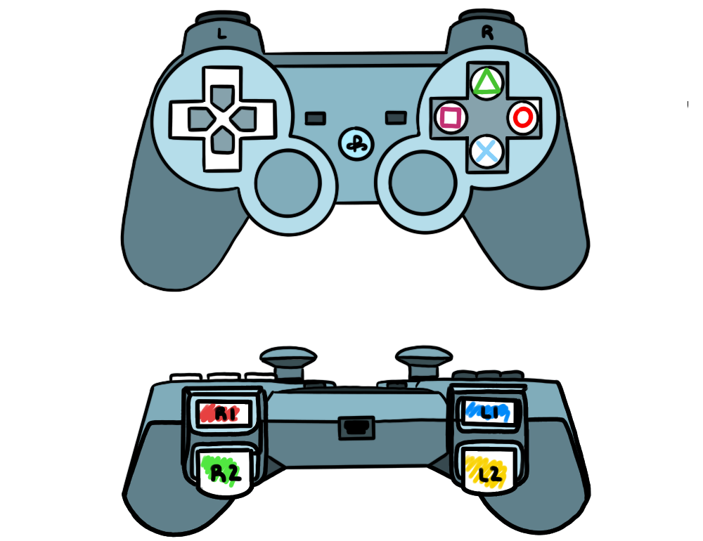
 LED’s
LED’s