Final IM project – sound visualizer

Documentation:

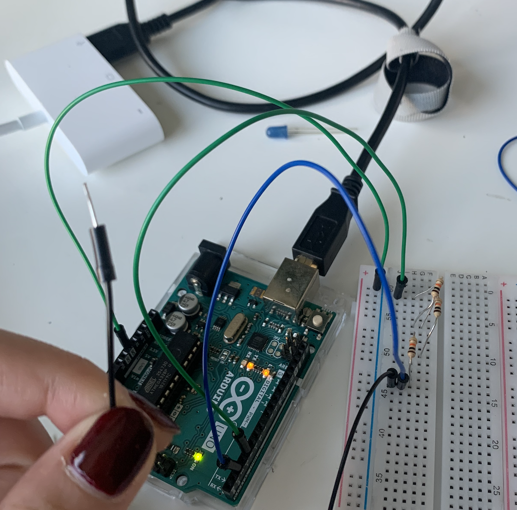
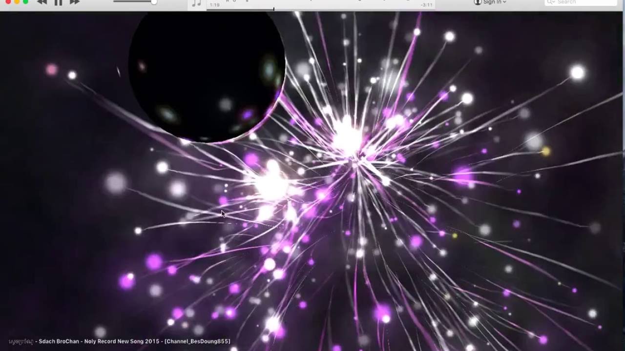
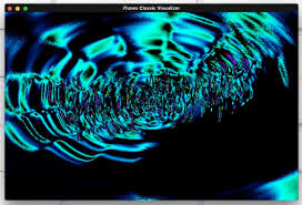
Idea: To create motion graphics that respond to sound frequency and amplitude and have input from Arduino to change the appearance of the visuals.

Artistic concept: Using geometry , 3D boxes specifically.

What was done well:

I think the composition of the 3D shapes is aesthetically pleasing.

I successfully mapped potentiometer values to color change in the visuals.

What could I have done better:

Maybe included more input from the user side, like more sensors , but I was short on time.

Tidier code – as this was a learning process for me the code might be harder to follow.

What I learned:

How to use the minim and sound library, the project taught me a-lot about motion graphics and 3D design in processing.

//I used inspiration from this persons work
//https://github.com/KartikShrivastava/3d-Audio-Visualizer-P3D/commit/d811270ff38dff160a2bf211b38068cab54f1b50
//Song from :https://www.youtube.com/watch?v=MtbzPhj0biE
import ddf.minim.*;
import ddf.minim.analysis.*;
import ddf.minim.effects.*;
import ddf.minim.signals.*;
import ddf.minim.spi.*;
import ddf.minim.ugens.*;

import processing.serial.*;
Serial myPort;

int xColor=0;
int xColor1=0;


FFT fft;
AudioPlayer player;
Minim minim;
float rotateAll = 0;
int depth, flashTimer = 0;
boolean flash=false;
float x;
int spacing = 100;
int border = spacing*2; 
int amplification = 50;
int y = spacing; 

void setup() {
  stroke(0, 239, 135); 
  strokeWeight(5);
  printArray(Serial.list());
  String portname=Serial.list()[4];
  println(portname);
  myPort = new Serial(this, portname, 9600);

  size(900, 900, P3D);

  background(0);
  minim = new Minim(this);
  player = minim.loadFile("jingle.mp3");  
  player.play();

  fft = new FFT(player.bufferSize(), player.sampleRate());
}

void draw() {
  background(0, 20, 20);

  lights();
  //colorchange();
  drawback(); //background

  fft.forward(player.mix);

  pushMatrix();
  translate(width/2, height/2, -120);

  for (int i=0; i<24; i++) {
    pushMatrix();

    rotateY(180);

    x=x+1*0.01;
    translate(x, 200, 0);
    if (fft.getBand(i)*1 > 300) {

      if (i==4 && fft.getBand(i)*1 > 1000) {
        flash = true;
      }
    } else {
      //stroke(0, 239, 135); 

      float r=0 ;
      float b=255 ;
   
      r = map(xColor, 0, 600, 0, 100);
      b = map(xColor, 0, 600, 100, 0);
    
      //fill(0, 254, 179, 33); 
      fill(r, 300, b, r); 
      stroke(r, 0, b);
    }
    //box 1
    box(50, (-fft.getBand(i)*5) - 80, 50); 
    rotateY(270);
    popMatrix();
    pushMatrix();
    translate(width/2+x, height/2, 0);
    //box 2
    box(50, (-fft.getBand(i)*5) - 80, 50); 
    popMatrix();
    pushMatrix();
    translate(width/2, height/2+x, -200);
    //box3
    box(50, (-fft.getBand(i)*5) - 80, 50); 
    popMatrix();
    pushMatrix();
    translate(width/3, height/3+x, -200);
    //box4
    box(150, (-fft.getBand(i)*5) - 80, 50); 
    popMatrix();
    pushMatrix();
    translate(-100+x, 100, -400);
    //box5
    rotateX(180);
    box(150, (-fft.getBand(i)*5) - 80, 50); 
    popMatrix();
    rotateX(180);
    box(150, (-fft.getBand(i)*5) - 80, 50);
  }
  popMatrix();
}

void drawback() {

  strokeWeight(4);
  rectMode(CENTER);

  stroke(#ff6ec7);


  player.play();
  float amplitude = player.mix.level();
  fill(random(0), amplitude*155);
  int x = int(map(player.position(), 0, player.length(), 0, width/2));
  float frequency = player.mix.get(int(x))*spacing*amplification;


  rect(width/2, height/2, frequency, frequency);
  stroke(#1b03a3); 
  ellipse(width/2, height/2, frequency*100, frequency*100);
  filter( BLUR, 0.5 );
}

void serialEvent(Serial myPort) {
  xColor=myPort.read();

}
void setup() {
  // put your setup code here, to run once:
  Serial.begin(9600);
}

void loop() {
  // put your main code here, to run repeatedly:
  int sensor = analogRead(A0);

  delay(1); //avoid getting noisy values.
  sensor /= 4; //why is it incrementally devided by 4? maybe slow it down
  //also 2^8 is 256 or 1024/4 sends one byte at a time to the serial,


  Serial.write(sensor);

}

Final Project – Phase 1

  1. This week I thought about how to incorporate the physical components first into Arduino so that I can get the mechanisms working first before I go into creating a more artistic design.
  2. I plan to create a keyboard like design of aluminum tape keys that resemble the piano keys. Each key is a capacitative sensor that also trigger a different musical note.
  3. At the moment when the key is pressed, the duration of how long it is pressed will display an image on screen with the respective sound(synthesizer scale). Each key acts like a switch to activate the image.
  4. For now the images on screen are simple to make sure it works first.
  5. The composition of the visuals is the next part. Despite this being Phase 2 ,I managed to  experiment on processing the different effects I can achieve with sound and shapes. These aren’t guaranteed to be used in the final version but it allowed me to familiarize myself with the minim library in processing.

Troubles creating the capacitative sensor:

This was arguably a tricky part to fix because of the limited number of Ohms in our resistor, in order for a capacitive sensor to work you need a higher number, so after trial and error, I lined up the resistor in a series form and finally could get a reading from the serial port.

The black wire in my hand is the capacitive sensor

Screenshot from Max msp real time audio software that I am considering using with processing as a library exists for it. In this patcher image I created a synth with a virtual keyboard.

#include <CapacitiveSensor.h>

/*
   CapitiveSense Library Demo Sketch
   Paul Badger 2008
   Uses a high value resistor e.g. 10M between send pin and receive pin
   Resistor effects sensitivity, experiment with values, 50K - 50M. Larger resistor values yield larger sensor values.
   Receive pin is the sensor pin - try different amounts of foil/metal on this pin
*/


CapacitiveSensor   cs_4_2 = CapacitiveSensor(4, 2); // 10M resistor between pins 4 & 2, pin 2 is sensor pin, add a wire and or foil if desired

int ledPin = 12;
void setup()
{
  cs_4_2.set_CS_AutocaL_Millis(0xFFFFFFFF);
 // turn off autocalibrate on channel 1 - just as an example
  Serial.begin(9600);

}

void loop()
{

  long start = millis();
  long total1 =  cs_4_2.capacitiveSensor(30);


  //    Serial.print(millis() - start);        // check on performance in milliseconds
  //    Serial.print("\t");                    // tab character for debug windown spacing

  Serial.println(total1);                  // print sensor output 1

  //    Serial.print("\t");

  //  delay(10);
  // if (total1 > 0) {
  //    digitalWrite(ledPin, HIGH);
  //  }
  //  else {
  //    digitalWrite(ledPin, LOW);
  //  } worked to turn LED on

  // arbitrary delay to limit data to serial port
}
import processing.sound.*;
import ddf.minim.*;
Minim minim;
AudioPlayer song;
int spacing = 100;
import processing.serial.*;
Serial myPort;
int signal=0;
int border = spacing*2; 
int amplification = 50;
int y = spacing; 
float ySteps;
void setup() { 
  printArray(Serial.list());
  String portname=Serial.list()[4];
  println(portname);
  myPort = new Serial(this, portname, 9600);
  size(800, 800); 
  background(255); 
  strokeWeight(1); 
  stroke(0); 
  noFill();
  minim = new Minim(this);
  song = minim.loadFile("song.mp3");
}
void draw() {
  if (signal>0) {
    song.play();
    float amplitude = song.mix.level();
    noStroke();
    fill(random(255), amplitude*155);
    int x = int(map(song.position(), 0, song.length(), 0, width/2));
    float frequency = song.mix.get(int(x))*spacing*amplification;
    ellipse(width/2, height/2, frequency, frequency);
  }
}

void serialEvent(Serial myPort) {
  signal=myPort.read();
}

Final Project Proposal – Sound Visualizer


I’m taking inspiration from the interactive music piece, LINES, but using different sensors/analog and digital input to control the frequency of the sounds and introduce new sounds. The input from the sensors can add visual effects that move according to the frequency of sound. In addition the user can change the color hues, the amplitude and add different effects to create a sound and image piece via sensors and inputs.

Due to the number of effects and sound components, I will likely purchase more components for my Arduino kit.

Inputs:

  • Buttons.
  • Light sensors.
  • Potentiometers.
  • Distance sensor

Update from feedback session:

Add a UI card to guide the user in how to manipulate the visuals and sound coming from processing.


Falling blocks – shooting game

Concept:

I tried to create a first person shooter game with falling blocks that would result in a point when shot .

What went well :

I learned how to use OOP more effectively for both the falling blocks and bullets. I successfully attached a hardware component

What didn’t:

Games are not my strong suit as I couldn’t find a way to make collision detection work in this case.

Took a lot of code to write but couldn’t finish the collision detection.

How to improve:

Either choose a game that doesn’t involve collision detection or work on collision detection first.

import processing.serial.*;
Serial myPort;
int xPos=0;


//code for player and bullet borrowed and modified from
//https://forum.processing.org/two/discussion/26683/trying-to-get-bullets-to-shoot-with-void-mousepressed-but-nothing-happens
final float SPEED = 2; 
final float BULLET_SPEED = 4;
final int ellipse_WIDTH = 50; 
final int ellipse_HEIGHT = 50; 

int centerX, centerY; //width/2; //height/2;
float posX, posY;
float ellipsePos1X, ellipsePos2X, ellipsePos3X;
float ellipsePos3Y;
float bulletDiam = 10;
float bulletX, bulletY;
float x, y;

void setup() {
  size(500, 500);
  printArray(Serial.list());
  String portname=Serial.list()[3];
  println(portname);
  myPort = new Serial(this, portname, 9600);

  centerX = width/2;
  centerY = height/2;
  posX = centerX - ellipse_WIDTH/2;
  posY = height - ellipse_HEIGHT;
  rainFactory(numberOfRainDrops);
}

void draw() {
  background(200);

  drawGun();  
  moveShot();  
  drawShot();
  drawRain();
}


void drawGun() {
  ellipsePos1X = posX;
  ellipsePos2X = posX + ellipse_WIDTH;
  ellipsePos3X = posX + ellipse_WIDTH/2;
  ellipsePos3Y = posY - ellipse_WIDTH;
  fill(255);  
  //ellipse(posX+ellipse_WIDTH/2, posY +ellipse_HEIGHT/2, ellipse_WIDTH, ellipse_HEIGHT);
  ellipse(xPos, posY +ellipse_HEIGHT/2, ellipse_WIDTH, ellipse_HEIGHT);
}

void mousePressed() {
  bulletY = posY;
  bulletX = ellipsePos3X;
}

void drawShot() {
  fill(255, 0, 0);
  rect (xPos, bulletY, bulletDiam, bulletDiam);
}

void moveShot() {
  bulletY = bulletY - BULLET_SPEED;
} 
void serialEvent(Serial myPort) {
  xPos=myPort.read();
}

//___ new tab
int numberOfRainDrops = 10;

Rain[] rainDrops;

void drawRain() {
  for (int i=0; i<rainDrops.length; i++) {
    rainDrops[i].draw();
    rainDrops[i].update();
  };
};

void rainFactory(int quantity) {
  rainDrops = new Rain[quantity];
  for (int i = 0; i < quantity; i++) {
    float x = random(0, width);
    float y = random(0, height);
    float w = 20;
    float h = 40;
    float ySpd= random(2);
    Rain newRain = new Rain(x, y, w, h, ySpd);
    rainDrops[i] = newRain;
  };
  return;
}

class Rain {
  float width_, height_;
  float xPos, yPos, ySpeed;
  //color myColor = color(0);

  Rain(float x, float y, float w, float h, float ySpd) {
    width_ = w;
    height_ = h;
    xPos = x;
    yPos = y;
    ySpeed = ySpd;
  }

  void draw() {
    fill(255);
    rect(xPos, yPos, width_, height_);
  }

  void update() {
    yPos += ySpeed;
    if (yPos > height) {
      fill(0);
      yPos= 0;
    }
  }
}

/*Arduino code
void setup() {
  // put your setup code here, to run once:
  Serial.begin(9600);
}

void loop() {
  // put your main code here, to run repeatedly:
  int sensor = analogRead(A0);
  delay(1);
  sensor/=4;
  Serial.write(sensor);
}
*/

video of work in progress:


Analog Musical Instrument

const int blueButton = 6;
const int servoPin = 9;
const int songLength = 8;
const int tempo = 115;

const int noteC3 = 130;
const int noteD3 = 146;
const int noteE3 = 164;
const int noteF3 = 174;
const int noteG3 = 196;
const int noteA3 = 220;
const int noteB3 = 246;


const int noteC4 = 261;
const int noteD4 = 293;
const int noteE4 = 329;
const int noteF4 = 349;
const int noteG4 = 392;
const int noteA4 = 440;
const int noteB4 = 493;
const int noteC5 = 523;

const int noteD5 = 587;
const int noteE5 = 659;
const int noteF5 = 698;
const int noteG5 = 784;
const int noteA5 = 880;
const int noteB5 = 987;


//int musicNotes[] = {noteC4, noteD4, noteE4, noteF4, noteG4, noteA4, noteB4, noteC5};
int musicNotes[] = {noteC5, 0, noteE5, 0, noteG5, 0, noteB5, 0};
int musicNotes2[] = {noteC4, 0, noteE4, 0, noteG4, 0, noteB4, 0};
int musicNotes3[] = {noteC3, 0, noteE3, 0, noteG3, 0, noteB3, 0};
int noteDuration[] = {2, 4, 2, 4, 4, 2, 4, 2};

void setup() {
  pinMode(servoPin, OUTPUT);
  pinMode(blueButton, INPUT_PULLUP);
  Serial.begin(9600);
}
void loop() {
 lightSensor();
  button();


}

//new tab: button
void button() {

  
  bool bluebuttonState = digitalRead(blueButton);
  if (bluebuttonState == HIGH) {
    for (int i = 0; i < songLength; i++) {

      int duration =   noteDuration[i] * tempo;

      tone(servoPin, musicNotes2[i], duration);
      delay(duration); //make the length of the time = length of the musical note(frequency)
      delay(15);

    }
  }    else {
    for (int i = 0; i < songLength; i++) {

      int duration =   noteDuration[i] * tempo;

      tone(servoPin, musicNotes[i], duration);
      delay(duration); //make the length of the time = length of the musical note(frequency)
      delay(15);


    };


  };

};
//new tab light sensor
void lightSensor() {
  int analogValue = analogRead(A0);
 Serial.print(analogValue);
  if (analogValue < 10) {
   Serial.println(" - Dark");
//   //add music note here
  } else if (analogValue < 200) {
   Serial.println(" - Dim");
    for (int i = 0; i < songLength; i++) {

     int duration =   noteDuration[i] * tempo;

     tone(servoPin, musicNotes3[i], duration);
     delay(duration); //make the length of the time = length of the musical note(frequency)
     delay(15);

    }

  }  };


Documentation:

Idea: Create sound directly from Arduino, like a musical drone sound by changing the musical notes from C4 to C5 when you click on the button or change from either to a 3rd octave when you dim the light sensor (all by changing the frequency from within the motor).

Positives:

I like how I could manipulate the motor sound based on its frequency to create a tone and tempo.In addition to that I was able to play around with that frequency within the motor to create an array of musical notes with different octaves. Once I could adjust the tempo and time spacing between notes through looping the array, I was able to integrate that into different parts of the code.

I like that I was able to introduce different noises from the motor by adding in different components that trigger different sounds like the button and sensor.

This was also surprisingly fun compared to other assignments for me because I learned that Arduino could be used for more than just LED circuits etc but you can incorporate and manipulate other media like sound.

Negatives:

I don’t think its particularly musical, however I think it follows the rules of music in terms of octaves and musical notes.


Light Dimmer

Concept:

  • Replicate the dimming effect from film lights, and the dimmers attached to them that have a slow smooth transition.
const int led1 = 13;
const int led2 = 12;
const int led3 = 11;
const int led4 = 10;
const int led5 = 9;
const int led6 = 8;
const int led7 = 7;
const int led8 = 6;
const int button = 6;

int potpin = A0;
int potnum = 0; //values from potentiometer
int readValue;
int writeValue;

void setup() {
  // put your setup code here, to run once:
  pinMode(button, INPUT_PULLUP);
  pinMode(led1, OUTPUT);
  pinMode(led2, OUTPUT);
  pinMode(led3, OUTPUT);
  pinMode(led4, OUTPUT);
  pinMode(potpin, INPUT);
  Serial.begin(9600);
}

void loop() {
  //analog and leds
  readValue = analogRead(potpin);
  writeValue = (255. / 1023.) * readValue;
  // formula from https://toptechboy.com/lesson-11-arduino-circuit-to-dim-led-with-potentiometer/

  //  bool buttonState = digitalRead(button);
  analogWrite(led1, writeValue);
  analogWrite(led2, writeValue);
  analogWrite(led3, writeValue);
  analogWrite(led4, writeValue);
  potnum = analogRead(potpin);
  Serial.println(potnum);
  //digital button and leds
  // put your main code here, to run repeatedly:

  bool buttonState = digitalRead(button);
  Serial.println(button);
  if (buttonState == HIGH) {
    digitalWrite(led5, LOW);
    digitalWrite(led6, LOW);
    digitalWrite(led7, LOW);
    digitalWrite(led8, LOW);

  } else {

    digitalWrite(led5, HIGH);
    digitalWrite(led6, HIGH);
    digitalWrite(led7, HIGH);
    digitalWrite(led8, HIGH);

  };
}

first attempt

second attempt


LEDs and Buttons

  • Name of puzzle: Stop the bomb.
  • The idea of this puzzle was to find away to stop the lights from blinking with the right clicking combination.
  • I managed to configure the buttons and LEDs to separate digital pins and control them with code.However, I don’t know how to input the number of times the button was clicked in order to result in something.
  • In the end this became more of a learning experience, as it took me longer than expected to debug the mechanical components.
const int led = 8; //red
const int led2 = 10; //blue
const int led3 = 3;//green
const int blueButton = 6;
const int redButton = 5;
const int greenButton = 4;


void setup() {
  pinMode(led, OUTPUT);
  pinMode(led2, OUTPUT);
  pinMode(led3, OUTPUT);
  pinMode(blueButton, INPUT_PULLUP);
  pinMode(redButton, INPUT_PULLUP);
  pinMode(greenButton, INPUT_PULLUP);
};
void loop() {
  bool bluebuttonState = digitalRead(blueButton);
  bool redbuttonState = digitalRead(redButton);
  bool greenbuttonState = digitalRead(greenButton);


  if (bluebuttonState == HIGH) {
    digitalWrite(led, LOW);

  } else {
    digitalWrite(led, HIGH);

  };
  if (redbuttonState == HIGH) {
    digitalWrite(led, LOW);
    digitalWrite(led2, LOW);
    digitalWrite(led3, LOW);

  } else {
    digitalWrite(led, HIGH);
    digitalWrite(led2, HIGH);
    digitalWrite(led3, HIGH);

  };

  if (greenbuttonState == HIGH) {

    digitalWrite(led2, LOW);

  } else {

    digitalWrite(led2, HIGH);

  };

};

Mid term final documentation- The Shining.

Documentation:

  • The project started out as not knowing which artistic direction to take. Initially I wanted to create a tricycle based POV going through the halls of the outlook hotel inspired by the shining.
  • It was too challenging, so I tried to make a candy based game where when points were won, the character’s waist would grow in size.
  • I achieved some elements of it. But not fully (you can find the documentation for that in older posts.)
  • Finally, I decided to combine the two. A ghost going through the out look hotel, to find Johnny in the secret door if he does not collide with the falling candy droplets.
  • What I learned:
  • How to structure code more efficiently.
  • How to use classes and objects.
  • Deal with growing code.
  • compartmentalize
  • writing better comments
  • What I can improve on:
  • complex game mechanics
  • isolating code
  • sticking with one idea

mid term – zip file

Candy colored spiral visual effect

This has gone through many iterations of trial and error to get the coolest effect.

Im using spiraled ellipses as a main element for my mid term, so I have been experimenting with it.

Code for creating the spiral:

float angle;

float x;
float y;
void setup() {
  size(800, 800);
  noFill();
  shapeMode(CENTER);
}

void draw() {

  //fill(255);
   fill(255,200,200); //pale rose, change the color of the candy.
  ellipse(height/2, width/2, 600, 600);
  
  int hundred=100;
  //rotate(angle);

  for (int i=0; i<500; i+=100)

  { 
    strokeWeight(20);
    stroke(0); //change the color of the spiral
    noFill();
    ;
    arc(height/2, width/2, hundred+i, hundred+i, radians(180), radians(360) );
    arc(height/2-25, width/2, hundred*1.5+i, hundred*1.5+i, radians(0), radians(180));
  }
  //angle=angle+0.1;
  //save("mySpiral.jpg");
};

I exported the code above to a .jpg format to use as an image in the sketch below.

Code for the animation:

float angle;
PImage img;
void setup() {
  size(900, 900);
  img = loadImage("mySpiral.png");
};
void draw() {
    background(255);
  for (int i=0; i<width; i++) {
 
     translate(width/2+i, height/2+i);
  imageMode(CENTER);
  rotate(angle);
  image(img, 0, 0,300,300);
  
 
  }
 angle=angle+1*1;
}


Next step :

I would like each candy spiral to go through several colored versions of itself:


  for (int a= 0; a<1; a++) {
     save(random(20)+"spiral");
  }

This code allows different colored versions from random to be saved as a new version of itself , I plan on using the saved photos as part of a sprite sheet to add to the animation above.

Epileptic spiral

int y;
int size; 
int hundred;
float end;
void setup() {

  size(640, 400);
  background(255);

};
void draw() {

  noFill();
  stroke(0);
  
  //ellipse(width/2-25,height/2,50,50);
hundred = 100; 
  for (int i=0; i<width; i+=100) {
    strokeWeight(20);
    
    arc(320, 200, hundred+i, hundred+i, radians(180), radians(360) );
    arc(320-25, 200, hundred*1.5+i, hundred*1.5+i, radians(0), radians(180) );
     //interesting effect here
     filter(INVERT);
     
    ;
  };
  
  
};
void keyPressed() {
  fill(#FFE200);
  textSize(random(20,200));
  text(key,random(300),random(100,400));
  print(key);
};