
I unfortunately don’t have anything physical down for this week, but I have made a lot of my own blueprints for how everything will physically be put together.
After speaking with Professor Shiloh, I got a lot of ideas on how to go about assembling my skateboard controller. Prof. Shiloh showed us this tool that could measure the diameter of round axles and drill parts; I was thinking I could use that to measure the exact diameter of my skateboard truck hangars (the long metal piece). I’m expecting around 1.8 mm right now for the hangar diameter and around 8mm for the axle itself.
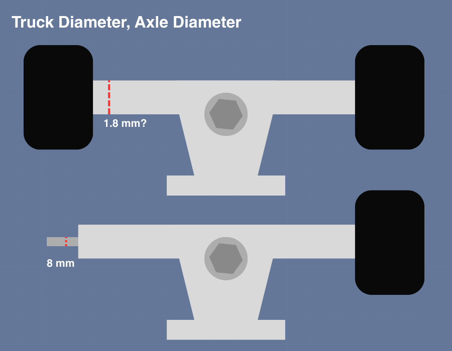
I’m probably going to create a hole with the size of the truck hangars in mind if possible; otherwise, I would need to create a hole for the truck axle to spin into, which might be a bit difficult. I want to build the frame in a way where I can take it apart for ease-of-transportation.
Mount Mechanism
For the mounting mechanism, I’m going to build a wooden frame to hold the board. I want it to be tilted forwards around 30 degrees for a more intense and immersive experience. The way I’m going to do that is to make the rear wheel support columns taller than the front ones. Here’s what it might look like:
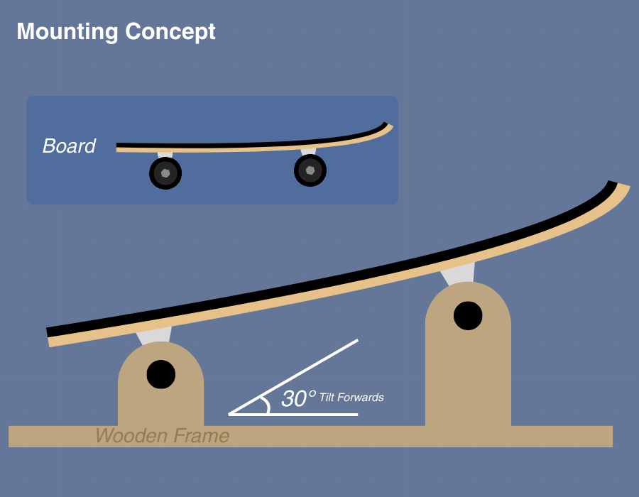
And this is a top-down view of the frame. It would have long extensions on each side to prevent the board from tipping over when the user is playing with the board. There’s no proper dimensions for this design yet but I’ll look into what length I would need each side to be for ideal safety standards.
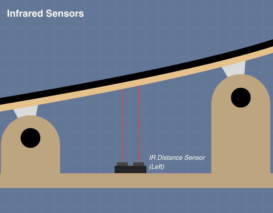
I’m going to be placing the infrared sensors on the wooden frame below the board. There would be a sensor on both the left and right of the board, which will provide input values to the Arduino. The reason they aren’t going on the board is because then the sensors would tilt with the board, disallowing it from detecting true distance from the ground. This is roughly what it will look like:
Arduino Input & Output
The Arduino is going to take the two Infrared Distance sensors as an input (in millimeters). It’s going to do some quick calculations to estimate the degree of tilt based on the two sensors and output a value for the tilt; It’s probably going to use arbitrary units from -100 to 100 where 0 is perfectly neutral and not tilted while negative 100 is tilting far left and positive 100 is tilting far right.
P5 Input & Output
The P5 side of things is going to take the -100 to 100 scale from the Arduino output and likely map it to what the user is controlling. If the user is controlling the X-position of a ball, the board tilting left would cause the ball to slide to the right. It’s kinda like the video game Super Monkey Ball where you physically tilting your controller (gyro controls) causes the level to tilt and subsequently roll the ball around.
This would require some physics-like exponential mapping that I’m not quite sure how to do yet but I can imagine this already being a really fun experience.