
Concept:
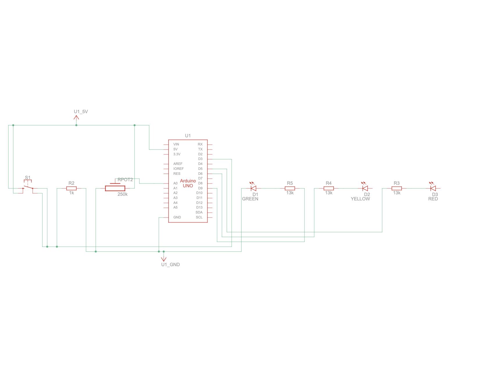
For my project, I wanted to create a system that could control multiple LEDs in both a digital and an analog fashion, and I drew inspiration from traffic lights. Instead of just two LEDs, I decided to use three LEDs to mimic a simplified traffic light sequence. When the push button is pressed, the system cycles through the lights in order: red → yellow → green, which demonstrates digital control, as each LED turns fully on or off with each button press.
For the analog aspect, I incorporated a potentiometer connected to an analog input pin on the Arduino. By adjusting the potentiometer, users can control the brightness of the LEDs, allowing for smooth, variable light intensity. Together, the push button and potentiometer create an interactive system: pressing the button cycles through the traffic light colors, while turning the potentiometer adjusts their brightness. This combination not only makes the project functional and educational but also connects to the familiar real-world concept of traffic lights.
Arduino Setup and Demonstration:
Coding:
// Pins
const int POTENTIOMETER_PIN = A0; // Analog input pin for potentiometer
const int BUTTON_PIN = 2; // Digital input pin for push button
const int RED = 5;  // Digital output pin for RGB LED (red)
const int GREEN = 6;  // Digital output pin for RGB LED (green)
const int YELLOW = 9; // Digital output pin for RGB LED (yellow)

// Variables
int potentiometerValue = 0; // Potentiometer value
bool buttonState = false; // Button state
int colorIndex = 0; // Index of current color

void setup() {
  pinMode(POTENTIOMETER_PIN, INPUT);
  pinMode(BUTTON_PIN, INPUT_PULLUP);
  pinMode(RED, OUTPUT);
  pinMode(GREEN, OUTPUT);
  pinMode(YELLOW, OUTPUT);
}

void loop() {
  potentiometerValue = analogRead(POTENTIOMETER_PIN);

  // Map potentiometer value to LED brightness
  int brightness = map(potentiometerValue, 0, 1023, 0, 255);

  // Set the LED color based on the current color index
  switch (colorIndex) {
    case 0:  // Red
      analogWrite(RED, brightness);
      analogWrite(GREEN, 0);
      analogWrite(YELLOW, 0);
      break;
    case 1:  // Green
      analogWrite(RED, 0);
      analogWrite(GREEN, brightness);
      analogWrite(YELLOW, 0);
      break;
    case 2:  // Yellow
      analogWrite(RED, 0);
      analogWrite(GREEN, 0);
      analogWrite(YELLOW, brightness);
      break;
  }

  // Check button state
  if (digitalRead(BUTTON_PIN) == LOW) {
    if (!buttonState) {
      // Toggle color index
      colorIndex = (colorIndex + 1) % 3;
      buttonState = true;
      delay(200);
    }
  } else {
    buttonState = false;
  }
}

