Partner: Hayeon Jeong
EXERCISE 01: ARDUINO TO P5 COMMUNICATION
Make something that uses only one sensor on arduino and makes the ellipse in p5 move on the horizontal axis, in the middle of the screen, and nothing on arduino is controlled by p5.
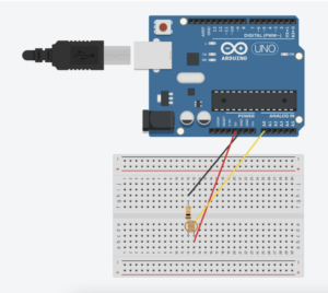
To complete this exercise, we built a simple circuit as illustrated below. We used the photocell to control the horizontal movement of the ball in p5.
As it is illustrated in the code for Arduino, most of it is similar to that of the one provided to the class. The things we changed are mostly done inside the void loop(). Since the Arduino is sending information to p5, we readjusted the code so that data is sent unidirectionally to p5: the value collected in A0 from the photocell is sent to p5.
Arudino Code
int leftLedPin = 2;
int rightLedPin = 5;


void setup() {
 // Start serial communication so we can send data
 // over the USB connection to our p5js sketch
 Serial.begin(9600);


 // We'll use the builtin LED as a status output.
 // We can't use the serial monitor since the serial connection is
 // used to communicate to p5js and only one application on the computer
 // can use a serial port at once.
 pinMode(LED_BUILTIN, OUTPUT);


 // Outputs on these pins
 pinMode(leftLedPin, OUTPUT);
 pinMode(rightLedPin, OUTPUT);


 // Blink them so we can check the wiring
 digitalWrite(leftLedPin, HIGH);
 digitalWrite(rightLedPin, HIGH);
 delay(200);
 digitalWrite(leftLedPin, LOW);
 digitalWrite(rightLedPin, LOW);


 // start the handshake
 while (Serial.available() <= 0) {
   digitalWrite(LED_BUILTIN, HIGH); // on/blink while waiting for serial data
   Serial.println("0,0"); // send a starting message
   delay(300);            // wait 1/3 second
   digitalWrite(LED_BUILTIN, LOW);
   delay(50);
 }
}


void loop() {
 // wait for data from p5 before doing something
     int sensor = analogRead(A0);
     delay(5);
     Serial.println(sensor);
 }
On p5, we drew an ellipse and initialized a variable ‘xposition’ that is used to move the horizontal position of the ball. Then under ‘if (data != null) {}’, we set the xposition = data where data refers to the value that is collected and sent from Arduino. This data is used to change the xposition of the ball in p5.
let rVal = 0;
let alpha = 255;
let xposition = 100;


function setup() {
  createCanvas(640, 480);
  textSize(18);
}


function draw() {
  // one value from Arduino controls the background's red color
  background(map(rVal, 0, 1023, 0, 255), 255, 200);


  ellipse(xposition, height/2, 50, 50);

  // the other value controls the text's transparency value
  fill(255, 0, 255, map(alpha, 0, 1023, 0, 255));


  if (!serialActive) {
    text("Press Space Bar to select Serial Port", 20, 30);
  } else {
    text("Connected", 20, 30);
    // Print the current values
    text('rVal = ' + str(rVal), 20, 50);
    text('alpha = ' + str(alpha), 20, 70);
  }


function keyPressed() {
  if (key == " ") {
    // important to have in order to start the serial connection!!
    setUpSerial();
  }
}


// This function will be called by the web-serial library
// with each new *line* of data. The serial library reads
// the data until the newline and then gives it to us through
// this callback function
function readSerial(data) {
  ////////////////////////////////////
  //READ FROM ARDUINO HERE
  ////////////////////////////////////


  if (data != null) {
    // make sure there is actually a message
    // split the message
    xposition = data;
    }


    //////////////////////////////////
    //SEND TO ARDUINO HERE (handshake)
    //////////////////////////////////
    let sendToArduino = left + "," + right + "\n";
    writeSerial(sendToArduino);
  }
EXERCISE 02: P5 TO ARDUINO COMMUNICATION
Make something that controls the LED brightness from p5.
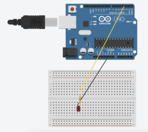
For this exercise, we utilized the position of mouseX from p5 to control the brightness of the LED on Arduino. The circuit we made looks like this:
Here, Arduino receives information from p5 and changes the brightness of the LED. Under void loop(), we used the map function to convert the values to PWM range and used analogWrite to set the LED brightness according to the value received from p5.
ARDUINO CODE
int LEDpin = 3;  // Ensure this pin supports PWM
void setup() {
 Serial.begin(9600);
 pinMode(LED_BUILTIN, OUTPUT);
 pinMode(LEDpin, OUTPUT);


 // Initial blink to confirm working setup
 digitalWrite(LEDpin, HIGH);
 delay(200);
 digitalWrite(LEDpin, LOW);


 // Wait for initial data before proceeding
 while (Serial.available() <= 0) {
   digitalWrite(LED_BUILTIN, HIGH);  // Blink LED to indicate waiting for connection
   Serial.println("0,0");  // Send a starting message
   delay(300);
   digitalWrite(LED_BUILTIN, LOW);
   delay(50);
 }
}


void loop() {
 if (Serial.available() > 0) {
   digitalWrite(LED_BUILTIN, HIGH);  // LED on while receiving data
   int bright = Serial.parseInt();
   bright = map(bright, 0, 640, 0, 255);  // Adjust received value to PWM range


   if (Serial.read() == '\n') {
     analogWrite(LEDpin, bright);  // Set LED brightness
   }
   digitalWrite(LED_BUILTIN, LOW);  // Turn off status LED after handling data
   Serial.println(0);
 }
}
In p5, we used mouseX and its position on the canvas to control the brightness of the LED on Arduino. We initialized a variable LEDbright to 0 but then let it change according to the if statement. If mouseX <= width && mouseX >= 0 && mouseY <= height && mouseY >= 0 , then the variable LEDbright is mouseX and this data is then sent to Arduino which controls the brightness of the LED. However, if the condition is not satisfied, then the variable LEDbright remains 0. Simply put, the LED lights up brighter when the mouse is on the right side of the screen and dimmer when it is on the left side of the screen.
P5.JS CODE
let LEDbright = 0;

function setup() {
  createCanvas(640, 480);
  textSize(18);
}

function draw() {

  background(205);

  // the other value controls the text's transparency value
  fill(0)

  if (!serialActive) {
    text("Press Space Bar to select Serial Port", 20, 30);
  } else {
    text("Connected", 20, 30);

  }

  // when clicked, digital LED will turn on,
  // other analog write LED will have brightness corresponding to the height of the mouse when it is press. can be pressed and dragged for controlling brightness
  if (mouseX <= width && mouseX >= 0 && mouseY <= height && mouseY >= 0) {
      LEDbright = mouseX;
  } else {
    LEDbright = 0;
  }
}

function keyPressed() {
  if (key == " ") {
    // important to have in order to start the serial connection!!
    setUpSerial();
  }
}

function readSerial(data) {
  ////////////////////////////////////
  //READ FROM ARDUINO HERE
  ////////////////////////////////////

    //////////////////////////////////
    //SEND TO ARDUINO HERE (handshake)
    //////////////////////////////////

    //send the posiiton of mouseY when clicked to control brightness
    let sendToArduino = LEDbright + "\n";
    writeSerial(sendToArduino);

}
EXERCISE 03: BI-DIRECTIONAL COMMUNICATION
Take the gravity wind example and make it so:
- every time the ball bounces one led lights up and then turns off,
- and you can control the wind from one analog sensor
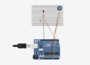
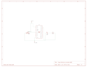
To complete this assignment, we used a potentiometer as an input to control wind and an LED as an output controlled by the bouncing ball in p5.js.
P5.JS CODE
let velocity;
let gravity;
let position;
let acceleration;
let wind;
let drag = 0.99;
let mass = 50;
let light = 0;

function setup() {
  createCanvas(640, 360);
  noFill();
  position = createVector(width/2, 0);
  velocity = createVector(0,0);
  acceleration = createVector(0,0);
  gravity = createVector(0, 0.5*mass);
  wind = createVector(0,0);
}

function draw() {
  background(255);
  applyForce(wind);
  applyForce(gravity);
  velocity.add(acceleration);
  velocity.mult(drag);
  position.add(velocity);
  acceleration.mult(0);
  fill('black')

   if (!serialActive) {
    text("Press Space Bar to select Serial Port", 20, 30);
  } else {
    ellipse(position.x,position.y,mass,mass);
  if (position.y > height-mass/2) {
      velocity.y *= -0.9;  // A little dampening when hitting the bottom
      position.y = height-mass/2;
    light=1

    }
    else{
      light=0
    }
  }
}

function applyForce(force){
  // Newton's 2nd law: F = M * A
  // or A = F / M
  let f = p5.Vector.div(force, mass);
  acceleration.add(f);
}

function keyPressed() {
  if (key == " ") {
    // important to have in order to start the serial connection!!
    setUpSerial();
  }
}


function readSerial(data) {
  ////////////////////////////////////
  //READ FROM ARDUINO HERE
  ////////////////////////////////////

  if (data != null) {
    // make sure there is actually a message
    // split the message
    let fromArduino = split(trim(data), ",");
    // if the right length, then proceed
    if (fromArduino.length == 1) {
      // only store values here
      // do everything with those values in the main draw loop

      // We take the string we get from Arduino and explicitly
      // convert it to a number by using int()
      // e.g. "103" becomes 103

      let sensorValue = int(fromArduino[0]);
      wind.x = map(sensorValue, 0, 1023, -1, 1);
    }
    }


    //////////////////////////////////
    //SEND TO ARDUINO HERE (handshake)
    //////////////////////////////////
    let sendToArduino = light + "\n";
    writeSerial(sendToArduino);
  }
ARDUINO CODE
int LEDpin = 2;
int wind = A0;

void setup() {
  // Start serial communication so we can send data
  // over the USB connection to our p5js sketch
  Serial.begin(9600);

  // We'll use the builtin LED as a status output.
  // We can't use the serial monitor since the serial connection is
  // used to communicate to p5js and only one application on the computer
  // can use a serial port at once.
  pinMode(LED_BUILTIN, OUTPUT);

  // Outputs on these pins
  pinMode(LEDpin, OUTPUT);
  pinMode(wind, INPUT);


  // start the handshake
  while (Serial.available() <= 0) {
    digitalWrite(LED_BUILTIN, HIGH); // on/blink while waiting for serial data
    Serial.println("0,0"); // send a starting message
  }
}

void loop() {
  // wait for data from p5 before doing something
  while (Serial.available()) {
    digitalWrite(LED_BUILTIN, HIGH); // led on while receiving data

    int light = Serial.parseInt();
    if (Serial.read() == '\n') {
      digitalWrite(LEDpin, light);
      int sensor = analogRead(A0);
      delay(5);
      Serial.println(sensor);
    }
  }
  digitalWrite(LED_BUILTIN, LOW);
}
To briefly explain this code, every time the ball hits the ground, the variable ‘light’ is set to 1. If this is not the case, ‘light’ is set to 0.
if (!serialActive) {
    text("Press Space Bar to select Serial Port", 20, 30);
  } else {
    ellipse(position.x,position.y,mass,mass);
  if (position.y > height-mass/2) {
      velocity.y *= -0.9;  // A little dampening when hitting the bottom
      position.y = height-mass/2;
    light=1

    }
    else{
      light=0
    }
  }
}
Then, p5.js sends the value of ‘light’ to the Arduino.
let sendToArduino = light + "\n";
    writeSerial(sendToArduino);
When the Arduino receives the light value from p5.js, it turns on if the value is 1 and turns off if the value equals 0.
int light = Serial.parseInt();
    if (Serial.read() == '\n') {
      digitalWrite(LEDpin, light);
To control the wind value, if the length of the data sensed by the Arduino is equal to 1, p5.js receives the data value of the potentiometer. We then use the map function to convert the analog input value from 0 to 1023 to a range of -1 to 1.
if (data != null) {
   // make sure there is actually a message
   // split the message
   let fromArduino = split(trim(data), ",");
   // if the right length, then proceed
   if (fromArduino.length == 1) {
     // only store values here
     // do everything with those values in the main draw loop

     // We take the string we get from Arduino and explicitly
     // convert it to a number by using int()
     // e.g. "103" becomes 103

     let sensorValue = int(fromArduino[0]);
     wind.x = map(sensorValue, 0, 1023, -1, 1);
   }
   }


