
For the final project, I will create an interactive virtual gallery that will respond to the user input through a variety of sensors to guide them to a direction in the gallery. The works themselve are interactive as well, on a smaller scale, where each explore a different output, such as sound and visuals. The concept behind it is exploring the intersection between interactivity and the different themes we explored through class and the reading, to provide a viewer of the work with an engaging experience where they get to see a reflection of their actions, giving them control over the work.
Month: November 2025
Final Project Preliminary Concept: Motion-Responsive Interactive Art Installation
For my final project, I want to create a motion-responsive interactive installation. The idea is that a user’s movements will be sensed by Arduino sensors, like an ultrasonic sensor, and sent to p5.js, which will process the input and generate dynamic visuals. I haven’t yet decided on the exact type of art to display; it could be abstract particle systems, animated images, or other digital creations. However, the key is that the visuals will respond in real-time to the user’s motion, making the experience immersive and engaging.
A recent trip I made to teamLab Phenomena, where I experienced installations that react to human gestures, is the inspiration behind this project. For example, moving through a space could cause flowers to bloom digitally or change the colors of projected visuals. I want to recreate that sense of wonder and interaction in my own project, where the user feels connected to the digital environment.
This project will be bidirectional.
-
Arduino → p5.js: The user’s gestures are sensed by Arduino and drive the visuals, controlling motion, shape, size, or color of the on-screen elements.
-
p5.js → Arduino: When the visuals reach certain thresholds, for instance, a cluster of particles grows large, or an animated image reaches a boundary, p5.js will send meaningful signals back to Arduino. These signals could trigger LEDs or small motors to give tactile feedback, making the interaction feel alive and responsive. This way, the user sees the effect on screen and feels it physically, creating a continuous loop of action and response.
Week 11: Reading Response
Design meets disability covers an important aspect of assistive technology that is often overlooked by the developers of such devices: design. The design aspect of these devices is built on the societal belief that disability is something to be ashamed of or something that needs to be hidden. Hence the discretion takes center in the design process, leaving behind aesthetics. Moving away from this belief and centering aesthetics over discretion would contribute to overcoming the stigma behind disability not only on an individual level, but on a societal level. The writer highlights the example of the glasses, that converted an assistive device from just a functional device to a fashion piece that is used as a method of expressing identity.
This shift in perspective that came from the focus on aesthetics caused a significant change on the view of visual impairments, that could be applied to other devices. That can only be achieved when designers begin viewing these devices as an essential part of everyday life rather than medical necessities, focusing on how they can be used by the users to display their identity. Converting devices such as hearing aids and prosthetic limbs to opportunities for expression rather than reminders of their differences. This was an important message as approaching the design of assistive technology with creativity and curiosity, would transform the field of development of assistive technology. Therefore, putting aesthetics in the forefront is not merely a matter of visual aspect. It involves acknowledging the emotional and social aspects of disability and creating designs that respect and promote visibility instead of pushing them into the shadows.
Week 11: Serial Communication
Exercise 1
For this exercise, we decided to use Ultrasonic sensor because we thought it will interesting to control the ellipse with our hand kind of like in video games Wii. Wherein based on your physical hand movement the objects move on the screen. To proceed with this idea, we first made a connection to the Arduino on P5.js, similar to how we did it in class. Then to control the x-axis we first read the serial write in P5.js and then mapped the value read from 0 to windowWidth. Another thing we noticed while performing this assignment is that the movement for ellipse was very abrupt and so we used a function called ‘lerp’. I had previously used this function for one of the P5 assignments and so I recalled that to smooth distance we can use this function. This function basically generates a value between my last x position to the current measured distance at certain interval (0.1 in this case). This makes sure that the circle moves in a smooth movement. Below I have attached my code to P5 and Arduino along with the demonstration video.
Exercise 2
For the second exercise, we chose to create a visual representation of the conversion from one side to another. Inspired by the chess clock, where time shifts between players while playing. We designed the LEDs so that as one grows brighter, the other dims, in turn symbolizing the passing of control from one side to the other. We started by first establishing the serial connection between Arduino and p5.js, similar to the previous exercise and what we did in class. In the p5 we created a slider ranging from 0 to 255, which we used to determine the brightness of LED 1, then for LED 2 we then set the inverse of that value so that as one increased, the other decreased. We continuously sent these two mapped values through serial in the format “value1,value2” and read them on the Arduino side to update the LED brightness using analogWrite. This setup allowed us to control both LEDs simultaneously from the browser and visually see the transition between them. Below are the p5.js and Arduino code along with the demonstration video.
Exercise 3
To complete this exercise we made changes to the gravity ball code provided. We first made sure that the LED lights up everytime the ball bounces to do so we maintained a state variable so everytime the ball touches ground we switched the state to HIGH else we set the state to LOW. This helped us achieve the goal. For the second module of this exercise, we decided to use our concept in exercise 1 i.e. ultrasonic sensor to control the wind movement of the ball. We looked at our distance from ultrasonic sensor and then decided to set a threshold of 50. So if the distance is >50, we set the wind speed to -3, else 3. This helped to move the ball in different directions and control it with our hand. We have provided the P5.js and Arduino code below for your references.
Final Project Idea
For my final project, I want to create a vocabulary learning system that uses hand gestures and light sensors to make memorizing words more engaging and physical. I’ve been thinking about how passive flashcard apps never really stick with me, and I’m curious whether tying words to actual movements might help them stay in my memory better. I want to focus on making the interaction feel natural and intuitive.
The basic idea is that I’ll have 2-3 photoresistors connected to Arduino, and my hand movements over them will control what appears on the P5 display. I’m imagining hovering my left hand to see just a definition, then hovering my right hand to reveal the actual word. I was also thinking maybe a quick swipe over both sensors could mark a word as learned and move it into a review pile, while holding my hand still might show an example sentence. What interests me most is building in a spaced repetition algorithm on the P5 side. I could have it track which words I struggle with and surface them more frequently, visualizing my progress over time. I’m also thinking it could be fun to add a “word of the day” feature that appears when I first turn it on, or maybe even pull from different vocabulary sets like GRE or LSAT words, academic writing terms, or just interesting words I encounter and want to remember.
Week 12: Serial Communication
For this week’s assignment, Zeina and I worked on three different exercises that focused on serial communication.
NOTE: We mostly used the exact copy of the arduino and p5 that was demoed in class with just an addition of 2-3 lines for each program. For these 2-3 lines we added comments, and for the rest of the lines we kept the same comments already included by the code
1- Make something that uses only one sensor on Arduino and makes the ellipse in p5 move on the horizontal axis, in the middle of the screen, and nothing on arduino is controlled by p5
ARDUINO CODE
void setup() {
  Serial.begin(9600);
}

void loop() {
  int sensorValue = analogRead(A1); // 0–1023
  Serial.println(sensorValue);             // send to p5.js
  delay(50);
}
P5 CODE
let port;
let connectBtn;
let baudrate = 9600;
let lastMessage = "";
let sensorValue = 0;

function setup() {
  createCanvas(400, 400);
  background(220);

  //Setting the global variable port to a new serial port instance inside setup:
  port = createSerial();

  // we can open ports we have used previously without user interaction
  let usedPorts = usedSerialPorts(); //array of used ports
  if (usedPorts.length > 0) {
    port.open(usedPorts[0], baudrate); //if any used port is in the array, open that port with 9600 baudrate
  }

  // any other ports (new ones) can be opened via a dialog after user interaction (see connectBtnClick below)
  connectBtn = createButton("Connect to Arduino");
  connectBtn.position(width/2, 270);
  connectBtn.mousePressed(connectBtnClick);

}

function draw() {
  background("white");

  // Read from the serial port. This is a non-blocking function. If a full line has come in (ending in \n), it returns that text. If the full line is not yet complete, it returns an empty string "" instead.
  let str = port.readUntil("\n");
  if (str.length > 0) {   // if str -a string- has any characters
    // print(str);
    lastMessage = str;
    sensorValue = int(lastMessage);
  }

  //draw ellipse mapped to horizontal axis
  let x = map(sensorValue, 0, 1023, 0, width);
  ellipse(x, height / 2, 40, 40);

  // Display the most recent message
  text("Last message: " + lastMessage, 10, height - 20);

  // change button label based on connection status
  if (!port.opened()) {
    connectBtn.html("Connect to Arduino");
  } else {
    connectBtn.html("Disconnect");
  }
}

function connectBtnClick() {
  if (!port.opened()) {
    port.open("Arduino", baudrate);
  } else {
    port.close();
  }
}
2-Make something that controls the LED brightness from p5
DEMO
ARDUINO CODE
// Week 12 Example of bidirectional serial communication

int leftLedPin = 2;
int rightLedPin = 5;

void setup() {
  Serial.begin(9600);

  pinMode(LED_BUILTIN, OUTPUT);
  pinMode(leftLedPin, OUTPUT);
  pinMode(rightLedPin, OUTPUT);

  digitalWrite(leftLedPin, HIGH);
  digitalWrite(rightLedPin, HIGH);
  delay(200);
  digitalWrite(leftLedPin, LOW);
  digitalWrite(rightLedPin, LOW);

  while (Serial.available() <= 0) {
    digitalWrite(LED_BUILTIN, HIGH);
    Serial.println("0,0");
    delay(300);
    digitalWrite(LED_BUILTIN, LOW);
    delay(50);
  }
}

void loop() {
  while (Serial.available()) {
    digitalWrite(LED_BUILTIN, HIGH);

    int left = Serial.parseInt();
    int right = Serial.parseInt();

    if (Serial.read() == '\n') {

      // -----------------------
      // ONLY CHANGE IS HERE:
      // -----------------------
      digitalWrite(leftLedPin, left);     // left stays ON/OFF
      analogWrite(rightLedPin, right);    // right is now BRIGHTNESS (0–255)
      // -----------------------

      int sensor = analogRead(A0);
      delay(5);
      int sensor2 = analogRead(A1);
      delay(5);
      Serial.print(sensor);
      Serial.print(',');
      Serial.println(sensor2);
    }
  }
  digitalWrite(LED_BUILTIN, LOW);
}
p5 CODE
let port; // making a var to hold the serial port
let baudrate = 9600; // speed for talking to arduino
let brightnessSlider; // slider to pick brightness
let smoothBrightness = 0; //transition into the brightness instead of jumping

function setup() {
  createCanvas(400, 200); // just making a small canvas for ui
  textSize(18); // bigger test

  brightnessSlider = createSlider(0, 255, 0); // slider from 0 to full bright
  brightnessSlider.position(20, 80); // where it shows up on screen
  brightnessSlider.style('width', '200px'); // make it a bit wider

  port = createSerial(); // create a serial object so we can connect to arduino

  let used = usedSerialPorts(); // check if we already used a port before
  if (used.length > 0) {
    port.open(used[0], baudrate); // auto connect to the last used port
  }
}

function setupSerial() {
  if (!port.opened()) { // if no connection yet
    port.open("Arduino", baudrate); // try to open one
  } else {
    port.close(); // if already open then close it (toggle)
  }
}

function draw() {
  background(240); // light grey

  if (!port.opened()) {
    text("Press SPACE to connect", 20, 30); // tell the user what to do
  } else {
    text("Connected!", 20, 30); // connection message
  }

  let target = brightnessSlider.value(); // get the slider value

  // do transitional brightness
  smoothBrightness = lerp(smoothBrightness, target, 0.07);


  text("Brightness: " + int(smoothBrightness), 20, 70); // show the number

  // actually send the brightness to the arduino
  if (port.opened()) {
    let sendString = "0," + int(smoothBrightness) + "\n"; // left=0 right=smooth
    port.write(sendString); // send it over serial
  }
}

function keyPressed() {
  if (key === " ") {
    setupSerial(); // hitting space toggles the port connection
  }
}
3-Take the gravity wind example (https://editor.p5js.org/aaronsherwood/sketches/I7iQrNCul) and make it so every time the ball bounces one led lights up and then turns off, and you can control the wind from one analog sensor
ARDUINO CODE
void setup() {
  pinMode(2, OUTPUT);
  Serial.begin(9600);
}

void loop() {
  int sensorValue = analogRead(A1);
  Serial.println(sensorValue);

  //check for bounce
  if (Serial.available() > 0) {
    //if 1, light up led
    if (Serial.parseInt() == 1) {
      digitalWrite(2, HIGH);
      delay(100);
      digitalWrite(2, LOW);
    }
  }
  delay(10);
}
P5.JS CODE
let velocity;
let gravity;
let position;
let acceleration;
let wind;
let drag = 0.99;
let mass = 50;
let port;
let connectBtn;
let baudrate = 9600;
let lastMessage = "";
let sensorValue = 0;

function setup() {
  createCanvas(640, 360);
  noFill();
  position = createVector(width / 2, 0);
  velocity = createVector(0, 0);
  acceleration = createVector(0, 0);
  gravity = createVector(0, 0.5 * mass);
  wind = createVector(0, 0);

  //Setting the global variable port to a new serial port instance inside setup:
  port = createSerial();


  // we can open ports we have used previously without user interaction
  let usedPorts = usedSerialPorts(); //array of used ports
  if (usedPorts.length > 0) {
    port.open(usedPorts[0], baudrate); //if any used port is in the array, open that port with 9600 baudrate
  }
// any other ports (new ones) can be opened via a dialog after user interaction (see connectBtnClick below)
  connectBtn = createButton("Connect to Arduino");
  connectBtn.position(width/2, 270);
  connectBtn.mousePressed(connectBtnClick);
}

function draw() {
  background(255);

  // Read from the serial port. This is a non-blocking function. If a full line has come in (ending in \n), it returns that text. If the full line is not yet complete, it returns an empty string "" instead.
  let str = port.readUntil("\n");
  if (str.length > 0) {   // if str -a string- has any characters
    // print(str);
    lastMessage = str.trim();
    sensorValue = int(lastMessage);
  }


  //wind controlled by analog sensor
  wind.x = map(sensorValue, 0, 1023, -1, 1);
  console.log("Sensor value: " + sensorValue);


  applyForce(wind);
  applyForce(gravity);

  velocity.add(acceleration);
  velocity.mult(drag);
  position.add(velocity);
  acceleration.mult(0);

  ellipse(position.x, position.y, mass, mass);

  // Bounce detection
  if (position.y > height - mass / 2) {
    velocity.y *= -0.9; // Dampening
    position.y = height - mass / 2;

    //send bounce signal to Arduino
    port.write("1\n");
  }
// Display the most recent message
  text("Last message: " + lastMessage, 10, height - 20);

  // change button label based on connection status
  if (!port.opened()) {
    connectBtn.html("Connect to Arduino");
  } else {
    connectBtn.html("Disconnect");
  }
}

function applyForce(force){
  // Newton's 2nd law: F = M * A
  // or A = F / M
  let f = p5.Vector.div(force, mass);
  acceleration.add(f);
}

function keyPressed(){
  if (keyCode==LEFT_ARROW){
    wind.x=-1;
  }
  if (keyCode==RIGHT_ARROW){
    wind.x=1;
  }
  if (key==' '){
    mass=random(15,80);
    position.y=-mass;
    velocity.mult(0);
  }
}

function connectBtnClick() {
  if (!port.opened()) {
    port.openDialog(); // user selects port
  } else {
    port.close();
  }
}
For this week’s reading assignment :
This reading made me really rethink the relationship between disability, design, and visibility. The author’s point about discretion was especially interesting, for example, how so many medical devices are intentionally designed to disappear, as if invisibility equals good design. But the reading also made me question what that invisibility actually communicates. If a product is meant to blend into the skin or look like it’s barely there, does that subtly imply that disability should be hidden? What is the further message?
The contrast with fashion added another interesting layer in my opinion. Fashion openly accepts the idea of being seen, of expressing identity, which is almost the opposite of traditional medical design. I liked the example of eyewear, which shows that a product can address a disability without carrying social stigma, and also can become something expressive and desirable. That overlap suggests disability-related products don’t need to be trapped between being “invisible” or “medical-looking,” and that they can have personality without becoming sensationalized.
Week 11 – Thoughts on Final Project
For my final project, I want to build something that makes the invisible visible. Specifically, the split-second biases we don’t even know we have.
My Idea
I’m designing an interactive system that captures implicit reaction bias through a combination of visual stimuli and physical sensors. There will be rapid-fire choices that measure not just if you respond, but how you respond. Do you press harder on certain choices? Do you hesitate before others? Our body knows things our conscious mind doesn’t want to admit.
How It Works
The p5.js component will display paired visual stimuli (e.g., shapes, colors, maybe even symbolic representations) that require quick binary decisions. Meanwhile, Arduino sensors capture the physical story: pressure sensors under each button measure response intensity, and an accelerometer tracks micro-movements and hesitations. I’m also considering adding a heart rate sensor to catch physiological stress during decision-making moments.
Why It Works
The power comes from the immediate feedback. As you go through trials, p5 visualizes your patterns in real-time, in color-coded displays showing where you reacted fastest, where you pressed hardest, where you hesitated. It’s confrontational in the best way: holding up a mirror to unconscious patterns we’d rather not see.
My Hesitation
This may be too psychological and not “art”, so people may question the interactivity of the “game”, or may not even recognize it as a game.
Week 11 Production(Ling and Abdelrahman)
Conceptualization:
The central idea was to build a simple connection between physical and digital worlds.
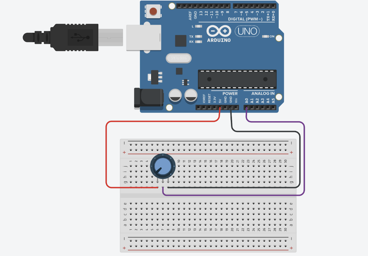
Exercise 1: Single-Sensor and p5.js Movement
Using only one analog sensor (a potentiometer), the Arduino continuously reads values and streams them to p5.js over serial. p5.js interprets those readings and moves an ellipse along the horizontal axis, keeping it vertically centered.
// exercise 1
void setup() {
 Serial.begin(9600);
  // wait for p5 to connect
 while (Serial.available() <= 0) {
   Serial.println("0,0");
   delay(300);
 }
}
void loop() {
 // wait for data from p5
 while (Serial.available()) {
   digitalWrite(LED_BUILTIN, HIGH);
    Serial.read();     // read incoming

   int sensorValue = analogRead(A0); // read sensor

   Serial.println(sensorValue);   // send sensor value
 }
 digitalWrite(LED_BUILTIN, LOW);
}
P5js: https://editor.p5js.org/aka7951/sketches/alRawYdiF
Demo https://drive.google.com/file/d/1Morf2y7cxIAgYLHKVnitsadjr813cX4Z/view?usp=sharing
Exercise 2: LED Brightness Controlled by p5.js
Next, I reversed the flow. Instead of only reading from Arduino, I sent numerical values from p5.js back to the board so it could adjust LED brightness using PWM.
int ledPin = 9;


void setup() {
 Serial.begin(9600);
 pinMode(ledPin, OUTPUT);
 pinMode(LED_BUILTIN, OUTPUT);
  // Wait for p5 connection
 while (Serial.available() <= 0) {
   digitalWrite(LED_BUILTIN, HIGH);
   delay(300);
   digitalWrite(LED_BUILTIN, LOW);
   delay(300);
 }
}
void loop() {
 if (Serial.available() > 0) {
   int brightness = Serial.parseInt();  // Read brightness value from p5
   analogWrite(ledPin, brightness);     // Set LED brightness

   if (Serial.read() == '\n') {
     digitalWrite(LED_BUILTIN, LOW);
   }
 }
}
P5js: https://editor.p5js.org/aka7951/sketches/tQoRTseMj
Demo: https://drive.google.com/file/d/1rdLpd3JG87jDa9bJEWZWtLMIvA9Ub0Vg/view?usp=sharing

Exercise 3: Gravity + Wind Integration
Finally, I modified the p5.js gravity wind sketch. Each time the ball hits the “ground,” p5 sends a signal to Arduino, turning an LED on briefly before switching back off. Meanwhile, an analog sensor feeds continuous data to p5.js to influence the wind force acting on the falling ball.
int ledPin = 5;


void setup() {
 Serial.begin(9600);
 pinMode(ledPin, OUTPUT);
  // wait for p5 to connect
 while (Serial.available() <= 0) {
   digitalWrite(LED_BUILTIN, HIGH);
   Serial.println("0");
   delay(300);
   digitalWrite(LED_BUILTIN, LOW);
   delay(50);
 }
}
void loop() {
 while (Serial.available()) {   //check if there's data from p5
   digitalWrite(LED_BUILTIN, HIGH);

   int ledValue = Serial.parseInt();     //read LED value from p5 (0 or 1)
   if (Serial.read() == '\n') {     // check for newline character
     digitalWrite(ledPin, ledValue);

     int sensorValue = analogRead(A0);  // read potentiometer value
     Serial.println(sensorValue);  // send sensor value back to p5
   }
 }
 digitalWrite(LED_BUILTIN, LOW);
}
P5js: https://editor.p5js.org/aka7951/sketches/ze7W5LcOi
Demo: https://drive.google.com/file/d/1c0O6wrqE6aStFpg9cvYVOke0zxojdR4Z/view?usp=sharing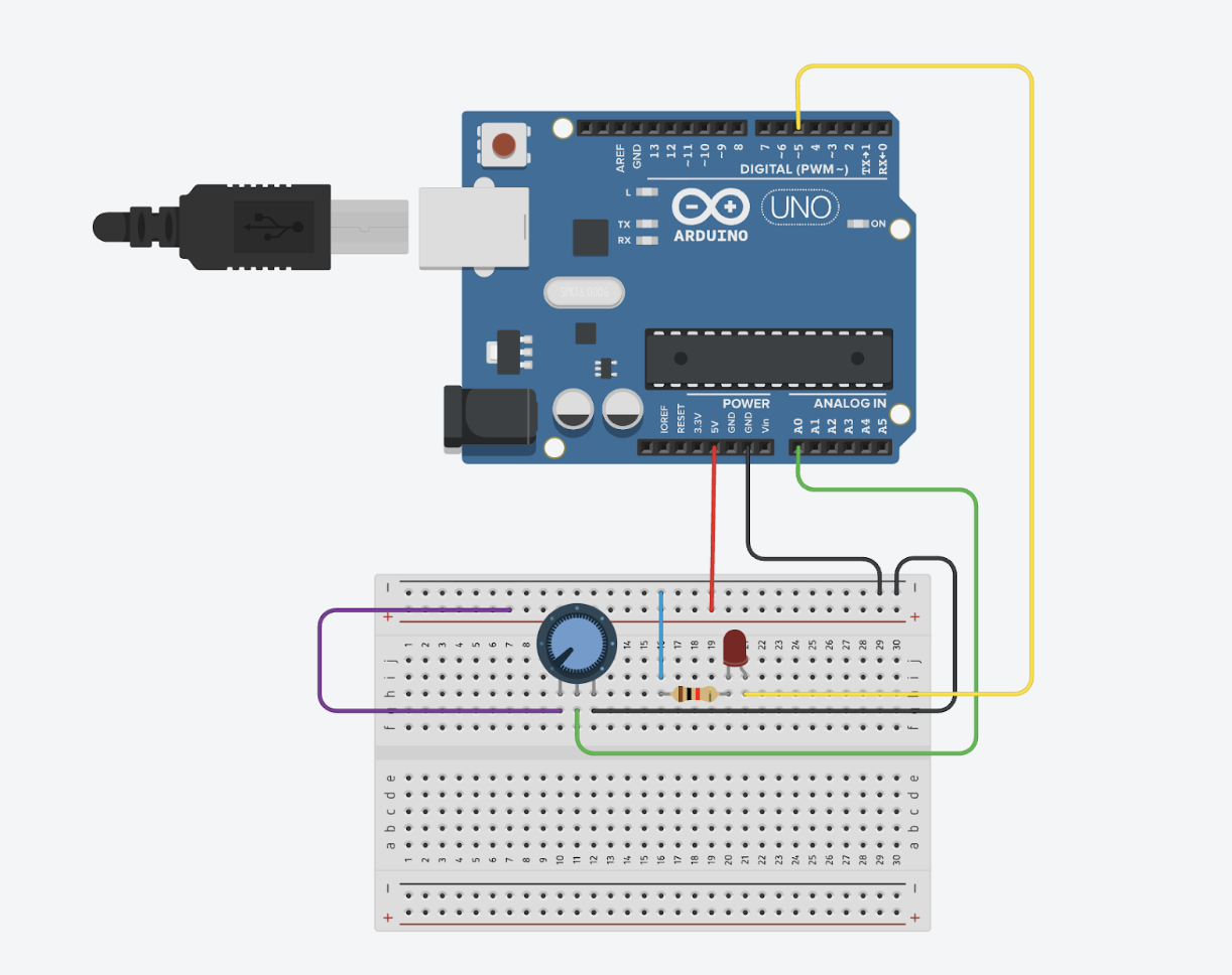
Reflection & Challenges:
This project helped me practice the bidirectional serial communication between Arduino and p5.js. One difficulty came from synchronizing input and output flows. In Exercises 2 and 3, sending and receiving serial data simultaneously often led to mixed or incomplete values being parsed. I learned to structure the serial communication carefully — ensuring each transmission ended with a newline and that both ends only read or wrote when data was available.
Final Project Idea
I am developing a small, battery-powered Arduino device that displays the room’s status and simple pixel-style emojis on a 16×2 LCD. The device is controlled wirelessly from my computer using either an nRF24L01 radio module or a Bluetooth serial module, depending on what hardware becomes available. The device will mount on a wall and serve as a minimal, visually friendly indicator of what’s happening inside the room.
Development Stages
Stage 1 — Crude Functional Prototype
My first goal is to build the simplest version of the system:
-
Connect an Arduino board, a 16×2 LCD, and whichever wireless module I choose.
-
Load basic firmware that listens for simple incoming messages and updates the LCD with status text and a small emoji.
-
Test commands from a computer program.
-
Focus on verifying communication and display logic, without worrying about wiring neatness, battery life, or enclosure design.
The objective of this stage is to prove that the device concept works end-to-end.
Stage 2 — Improved Prototype and Physical Enclosure
Once the first prototype is working, I move to making it usable in a real space:
-
Tidy the wiring and make the device compact.
-
Design a simple case in a 3D modeling tool such as Fusion 360 or Tinkercad.
-
3D-print the enclosure so the LCD is visible from the front, the electronics fit securely inside, and the device can mount flat against a wall.
-
Refine battery placement so the device can be opened or recharged easily.
Stage 3 — Final Visual and Interaction Refinement
After the device is physically assembled:
-
Adjust the display layout so the text and emoji look balanced and readable.
-
Refine how the device reacts to incoming commands (such as smoothing updates, adding small transitions, or improving clarity).
-
Add small visual improvements such as backlight changes for attention or custom character tweaks for better emoji expression.
This stage is about making the device feel polished and pleasant.
Project Architecture
Device Side:
The device contains three main elements:
-
Microcontroller — the Arduino runs the core program that listens for wireless messages and updates the display.
-
Display System — the 16×2 LCD shows both text and custom emoji characters.
-
Wireless Module — either an nRF24L01 or a Bluetooth serial module receives commands from my computer.
Internally, the Arduino software is structured around:
-
A small message handler that receives text commands wirelessly.
-
A display manager that decides what to show based on the message.
-
A custom character bank for emoji graphics.
This architecture keeps the device simple, efficient, and easy to maintain.
Computer Side
On my computer, I run a lightweight program that:
-
Opens a wireless communication link (either through a paired Bluetooth COM port or through a USB radio dongle for the nRF24L01).
-
Sends simple text commands such as “BUSY”, “AVAILABLE”, “MEETING”, or an emoji instruction.
-
Lets me manually choose the room status using a small interface or a command-line tool.
The computer-side software remains minimal because all visual work happens on the Arduino.
Emoji Design Approach
Since the 16×2 LCD uses a 5×8 pixel character grid, I design emojis as tiny pixel icons:
-
Create simple patterns — smiling, neutral face, busy face, resting face, or symbols like checkmarks or caution icons.
-
Define each pattern using the LCD’s built-in custom character feature.
Week 11 Production(Ling and Abdelrahman)
Conceptualization:
The central idea was to build a simple connection between physical and digital worlds.
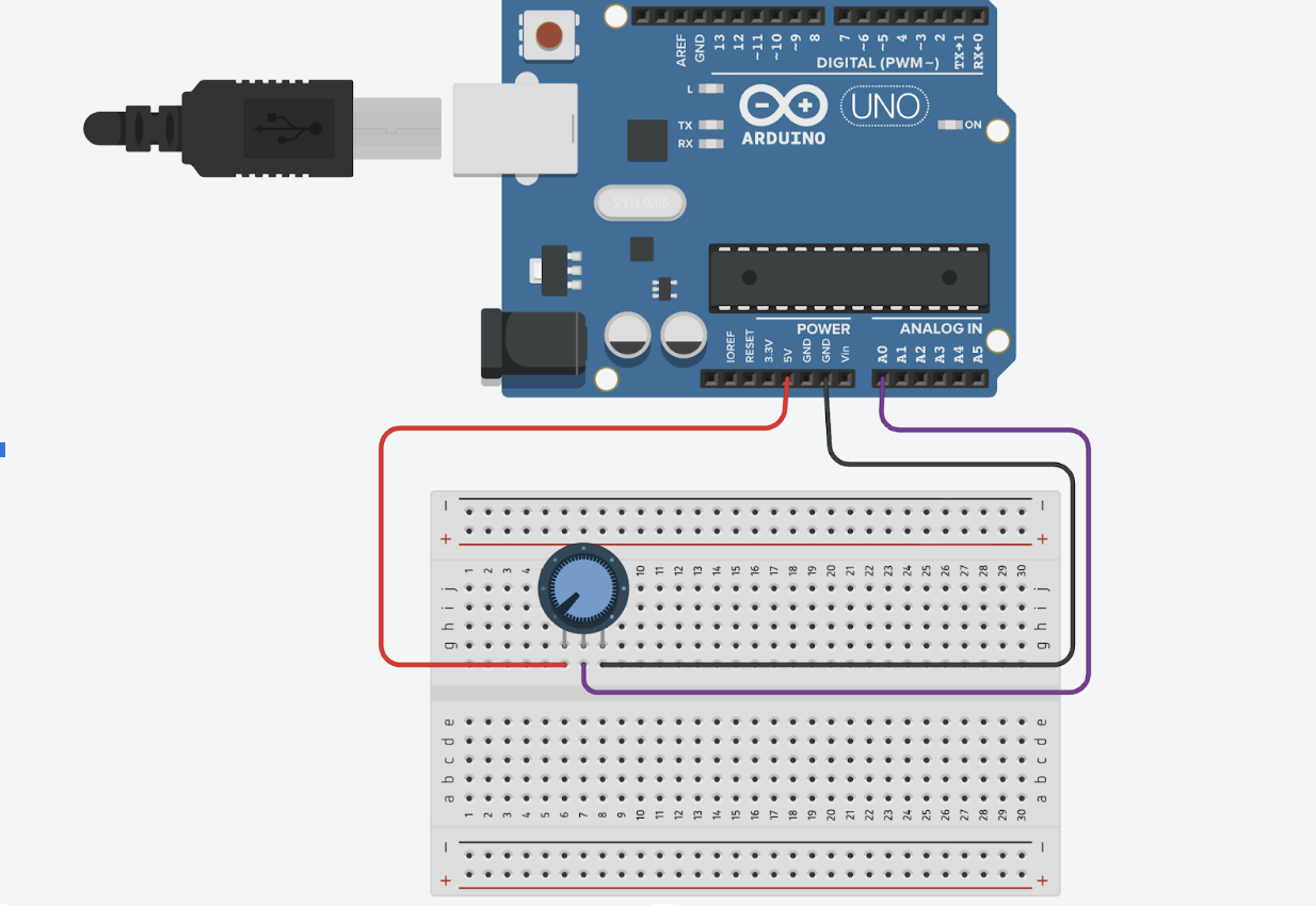
Step 1: Single-Sensor and p5.js Movement
Using only one analog sensor (a potentiometer), the Arduino continuously reads values and streams them to p5.js over serial. p5.js interprets those readings and moves an ellipse along the horizontal axis, keeping it vertically centered.
Step 2: LED Brightness Controlled by p5.js
Next, I reversed the flow. Instead of only reading from Arduino, I sent numerical values from p5.js back to the board so it could adjust LED brightness using PWM.
Step 3: Gravity + Wind Integration
Finally, I modified the p5.js gravity wind sketch. Each time the ball hits the “ground,” p5 sends a signal to Arduino, turning an LED on briefly before switching back off. Meanwhile, an analog sensor feeds continuous data to p5.js to influence the wind force acting on the falling ball.
Video Demonstration:
https://drive.google.com/file/d/1Morf2y7cxIAgYLHKVnitsadjr813cX4Z/view?usp=sharing
Schematic:
Code Highlight:
oid setup() {
 Serial.begin(9600);
  // wait for p5 to connect
 while (Serial.available() <= 0) {
   Serial.println("0,0");
   delay(300);
 }
}
void loop() {
 // wait for data from p5
 while (Serial.available()) {
   digitalWrite(LED_BUILTIN, HIGH);
    Serial.read();     // read incoming

   int sensorValue = analogRead(A0); // read sensor

   Serial.println(sensorValue);   // send sensor value
 }
 digitalWrite(LED_BUILTIN, LOW);
}
// serial variables
let port;
let connectBtn;
let sensorValue = 0;

function setup() {
  createCanvas(640, 360);

  port = createSerial();   // create serial connection

  // create connect button
  connectBtn = createButton("Connect to Arduino");
  connectBtn.position(10, 10);
  connectBtn.mousePressed(connectToArduino);
}

function draw() {
  background(220);

  // read from Arduino
  let str = port.readUntil("\n");
  if (str.length > 0) {
    sensorValue = int(str);
  }

  port.write("\n");   // send handshake to Arduino


  let xPos = map(sensorValue, 0, 1023, 0, width);   // map sensor to horizontal position

  // draw ellipse in middle vertically
  fill(0);
  ellipse(xPos, height/2, 50, 50);

  // show sensor value
  fill(0);
  noStroke();
  text("Sensor: " + sensorValue, 10, 50);
  text("Turn potentiometer to move circle", 10, 70);
}

// connect to Arduino
function connectToArduino() {
  if (!port.opened()) {
    port.open(9600);
  }
}
Reflection:
This project helped me practice the bidirectional serial communication between Arduino and p5.js.