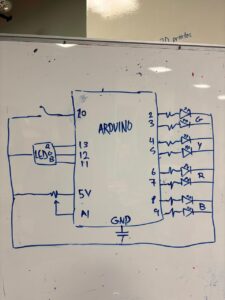
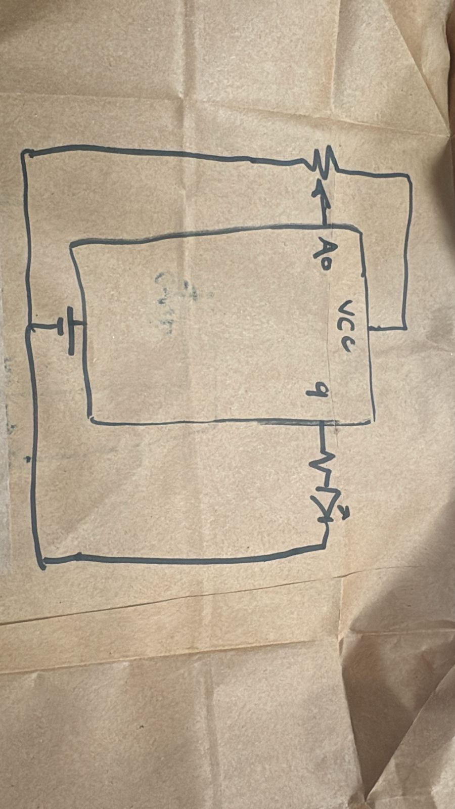
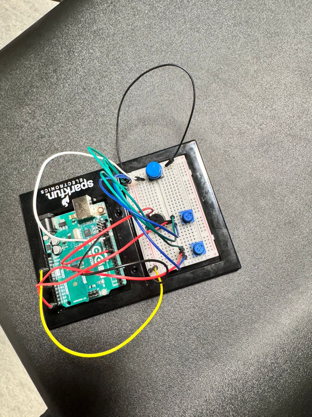
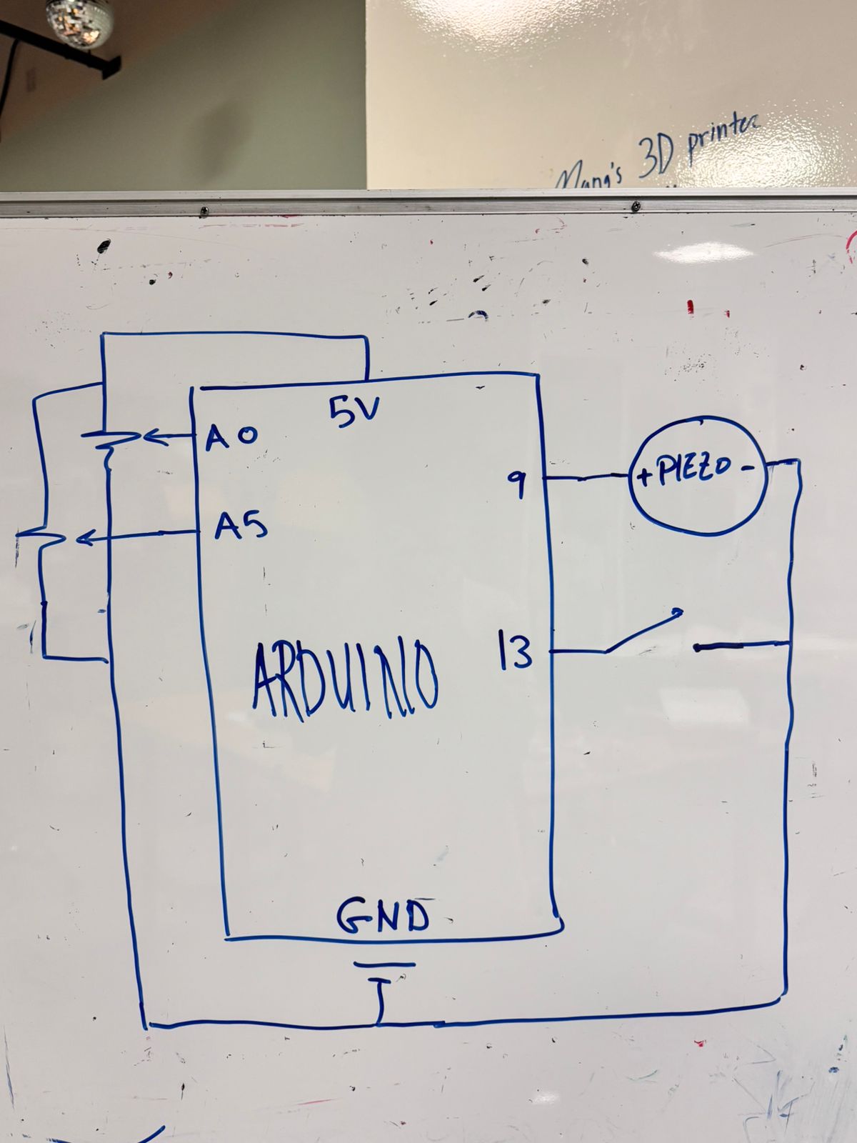
Preliminary Concept : Voice-Controlled Car (Speech to Movement)

Concept  : Voice-Controlled Car

The main idea is to build a car that responds to spoken words like “forward,” “left,” “right,” and “stop.”
Instead of a remote control or buttons, the user interacts only through speech, making the experience feel natural and intuitive.

Interaction (How it Works)

On the laptop, a p5.js sketch uses the SpeechRec library to listen through the microphone.
When the user says a direction:

  • “forward” → the car should drive straight

  • “left” → the car turns left

  • “right” → the car turns right

  • “stop” → the car stops moving

p5.js identifies the spoken word and sends the corresponding command through serial communication to the Arduino.

The Arduino receives these simple messages and activates the correct motors to move the car.
The entire system becomes a loop of:

You speak → p5 listens → p5 processes → Arduino moves the car

The goal is to make it feel almost like the car is “listening” and responding to the user in real time.

Arduino Components

  • 1 Arduino Uno

  • 2 DC motors (for movement and turning)

  • 1 motor driver (L298N or similar)

  • Wheels + chassis

  • External battery pack for the motors

  • USB cable for serial communication

I might later add optional components like LED indicators or a small buzzer that reacts to commands, depending on how the project develops.

Why I Like This Idea

I like this concept because it feels fun, intuitive, and a bit magical.
Anyone can walk up and immediately understand how it works since people naturally speak commands like “go” or “stop.”

Reading Reflection

When I read this, I was struck by how much it changed the way I see the things we design for people with disabilities. I always thought the main goal was to make these products as invisible and discreet as possible,  thus to hide the need for them. It made sense to me that if something was medical, it should be quiet and blend in.

But then the reading talked about glasses. I wear glasses, and I never think of them as a medical device. I think about which frames look good on me. I feel more confident in some pairs than others. The reading pointed out that glasses became successful not by being hidden, but by becoming a fashion item , it’s something people are proud to wear. This was a big shift in my thinking. Why should a hearing aid or a prosthetic leg be any different? Why does it have to be hidden or made from “skin-colored” plastic?

I loved the story about Aimee Mullins and her collection of legs. She has running legs, elegant legs, and even beautifully carved wooden legs that she matches with her outfits. To her, they are not just tools; they are part of her identity and style. That idea felt  human to me. It’s not about ignoring the disability, but about embracing it as part of who you are and even celebrating it through design.

It also made me realize that good design isn’t just about solving a problem in the most efficient way. It’s about emotion, identity, and culture. When designers from fashion or art get involved, they bring new perspectives. They ask not just “How does it work?” but “How does it make you feel?”

I now  see disability not as something to be corrected or hidden, but as a source of inspiration for more creative, more personal, and more beautiful design. It made me hope that in the future, everyone will have the option to use assistive products that they don’t just need, but truly love.

Week 11

Exercise 1: Arduino to p5.js  – Potentiometer

Concept

This project shows how a physical sensor can control a digital object. A potentiometer on the Arduino sends its values to p5.js . In the sketch, these values move an ellipse left or right on the screen. Turning the knob changes the ellipse’s position instantly. 

Arduino Code

The Arduino reads the potentiometer value and sends it over serial:

int interval = 100; // milliseconds between readings

void setup() {
  Serial.begin(9600); // start serial communication
}

void loop() {
  int potValue = analogRead(A1); // read potentiometer
  int mappedValue = map(potValue, 0, 1023, 0, 255); // scale value
  Serial.println(mappedValue); // send value to p5.js
  delay(interval); // avoid flooding serial
}

p5.js Code

The p5.js sketch reads the serial data and moves the ellipse:

let positionX = 0;
let port;
let sensorValue = 0;

function setup() {
  createCanvas(400, 400);
  positionX = width / 2;

  port = createSerial();
  let used = usedSerialPorts();
  if (used.length > 0) port.open(used[0], 9600);
}

function draw() {
  background(220);

  let line = port.readUntil("\n");
  if (line.length > 0) {
    sensorValue = int(line.trim());
  }

  positionX = map(sensorValue, 0, 255, 0, width);

  ellipse(positionX, height / 2, 50, 50);
}

Video of the final result : Video

Excercise 2 : p5.js-to-Arduino LED Control

Concept

This project demonstrates how a digital signal from p5.js can control hardware on Arduino. Using a p5.js sketch, we can send commands over serial to turn an LED on or off.

Arduino Code

The Arduino listens for serial commands from p5.js and controls the LED accordingly:

The Arduino listens for serial commands from p5.js and controls the LED accordingly:
int ledPin = 13; // onboard LED

void setup() {
  pinMode(ledPin, OUTPUT);
  Serial.begin(9600); // start serial communication
}

void loop() {
  if (Serial.available() > 0) {
    String command = Serial.readStringUntil('\n'); // read command
    command.trim(); // remove whitespace

    if (command == "ON") {
      digitalWrite(ledPin, HIGH); // turn LED on
    } 
    else if (command == "OFF") {
      digitalWrite(ledPin, LOW); // turn LED off
    }
  }
}

p5.js Code

The p5.js sketch sends commands to the Arduino based on events:

let port;
let connectBtn;

function setup() {
  createCanvas(400, 400);
  background(220);

  // initialize serial connection
  port = createSerial();
  let used = usedSerialPorts();
  if (used.length > 0) port.open(used[0], 9600);

  connectBtn = createButton("Connect");
  connectBtn.position(10, 10);
  connectBtn.mousePressed(toggleConnection);
}

function draw() {
  background(220);
}

function keyPressed() {
  if (port.opened()) {
    if (key === 'L') {         // press L to turn LED on
      port.write("ON\n");
    } else if (key === 'K') {  // press K to turn LED off
      port.write("OFF\n");
    }
  }
}

Video of the final result : Video

Excercise 3 : Bidirectional : Bouncing Ball with LED and Potentiometer

Concept

This project demonstrates bidirectional communication between Arduino and p5.js, combining physics simulation with hardware interaction. In this : A ball bounces on the p5.js canvas, following simple gravity physics. The horizontal wind affecting the ball is controlled by a potentiometer connected to Arduino. Turning the knob changes the wind force in real-time. Every time the ball hits the floor, p5.js sends a “BOUNCE” signal to Arduino, lighting up an LED. When the ball stops bouncing, p5.js sends a “STOP” signal, turning the LED off.

Arduino Code

Arduino reads the potentiometer and controls the LED based on serial commands:


int ledPin = 13;   // LED pin
int potPin = A1;   // potentiometer pin
int potValue = 0;

void setup() {
  pinMode(ledPin, OUTPUT);
  Serial.begin(9600);
}

void loop() {
  // Read potentiometer value
  potValue = analogRead(potPin);
  Serial.println(potValue);  // send to p5.js

  // Check for incoming serial commands
  if (Serial.available() > 0) {
    String command = Serial.readStringUntil('\n');
    command.trim();

    if (command == "BOUNCE") {
      digitalWrite(ledPin, HIGH);   // light LED on bounce
    } else if (command == "STOP") {
      digitalWrite(ledPin, LOW);    // turn LED off when ball stops
    }
  }

  delay(50); // small delay for stability
}

p5.js Code

The p5.js sketch simulates a bouncing ball and sends commands to Arduino:


let velocity, gravity, position, acceleration, wind;
let mass = 50;
let drag = 0.99;

// SERIAL
let port;
let sensorValue = 0;

function setup() {
  createCanvas(640, 360);
  noFill();

  // physics
  position = createVector(width/2, 0);
  velocity = createVector(0, 0);
  acceleration = createVector(0, 0);
  gravity = createVector(0, 0.5 * mass);
  wind = createVector(0, 0);

  // serial
  port = createSerial();
  let used = usedSerialPorts();
  if (used.length > 0) port.open(used[0], 9600);
}

function draw() {
  background(255);

  // read potentiometer from Arduino
  let line = port.readUntil("\n");
  if (line.length > 0) sensorValue = int(line.trim());
  wind.x = map(sensorValue, 0, 1023, -1, 1);

  // apply forces
  applyForce(wind);
  applyForce(gravity);

  velocity.add(acceleration);
  velocity.mult(drag);
  position.add(velocity);
  acceleration.mult(0);

  ellipse(position.x, position.y, mass, mass);

  // bounce detection
  if (position.y > height - mass/2) {
    position.y = height - mass/2;

    if (abs(velocity.y) > 1) {
      velocity.y *= -0.9;
      if (port.opened()) port.write("BOUNCE\n"); // LED on
    } else {
      velocity.y = 0;
      if (port.opened()) port.write("STOP\n");   // LED off
    }
  }
}

function applyForce(force) {
  let f = p5.Vector.div(force, mass);
  acceleration.add(f);
}

Video of the final result : Video


Challenges and Improvements

In all three projects, the hardest part was making sure the Arduino and p5.js talked to each other correctly. Sometimes the data from the potentiometer didn’t come through clearly, which made the ellipse or bouncing ball move strangely or the LED turn on and off at the wrong time. It was also tricky to scale the sensor values so they controlled the visuals in a smooth way. In the bouncing ball project, making the LED light only when the ball bounced was challenging because the ball slowed down naturally. To improve, I could smooth the sensor readings to make movement less jumpy, make the ball bounce more realistically, or add more sensors or LEDs for extra interaction. These changes would make the projects work better and feel more interactive.

Ref:  In the last exercise, ChatGPT helped us by explaining and guiding the use of p5.Vector, physics calculations, and serial communication, which made Implementation easier.

Week 11: Preliminary Concept for Final Project

For my final project, I’m currently deciding between two game concepts. I’m still brainstorming and working on the overall ideas, so since I haven’t fully decided what to go with yet, I’m documenting both possible directions.

Concept 1 — Rhythm Game

This concept is based on rhythm games like Dance Dance Revolution, but turned into a tabletop physical controller. Instead of tapping keys on a keyboard, players interact with physical buttons connected to an Arduino that trigger actions in p5.js.

Interaction (How it Works)

On the p5.js screen, colored notes fall from the top to the bottom. The player has 4–6 physical push buttons arranged in a row, each one corresponding to a lane on the screen. When a falling note reaches the bottom marker, the player must press the matching physical button at the right moment.

The game gives immediate feedback, such as:

  • Perfect hits respond with a sound and/or visual flash
  • A miss is indicated with a red flash
  • The score updates in real time

Arduino Components

  • 4–6 push buttons
  • 1 potentiometer

The potentiometer will control the difficulty level by adjusting the speed of the falling notes (higher difficulty = faster notes).

I like this idea because I think people will naturally want to try it, and it’s generally easy to understand without needing much explanation.


Concept 2 — Wizard Duel (Mashing Game)

This concept is a 2-player competitive game inspired by Harry Potter wand duels and by games like “Wizard” on 1-2-Switch. Each player has a physical button, and the faster they mash their button, the more they push their spell beam toward the opponent.

Interaction (How it Works)

The p5.js screen shows two wizards on opposite sides. Player 1 has one button, Player 2 has another. When the game starts (using a separate start/reset button):

  • Both players mash their button as fast as possible
  • The faster player pushes the spell beam toward the opposite side
  • If the beam reaches Player 2’s side, Player 1 wins
  • If it reaches Player 1’s side, Player 2 wins

Arduino Components

  • 1 button to start/reset
  • 2 buttons (one for each player to mash)

I might also add LEDs for each player that flash with every mash (not 100% sure yet, I’ll see what works best). I’m also open to adding more components if it makes the game more interesting.

I like this idea because I love competitive games, especially mashing games. I used to play them all the time on game consoles with my sisters.


Conclusion

I still need to decide which concept I’ll fully commit to (and who knows, I might even change my entire idea by next week). Over the next few days, I’ll prototype small parts of each idea to see which one feels more engaging and fun for me to complete.

Assignment Exercises

Exercise 1

For this exercise, we decided to use Ultrasonic sensor because we thought it will interesting to control the ellipse with our hand kind of like in video games Wii. Wherein based on your physical hand movement the objects move on the screen. To proceed with this idea, we first made a connection to the Arduino on P5.js, similar to how we did it in class. Then to control the x-axis we first read the serial write in P5.js and then mapped the value read from 0 to windowWidth. Another thing we noticed while performing this assignment is that the movement for ellipse was very abrupt and so we used a function called ‘lerp’. I had previously used this function for one of the P5 assignments and so I recalled that to smooth distance we can use this function. This function basically generates a value between my last x position to the current measured distance at certain interval (0.1 in this case). This makes sure that the circle moves in a smooth movement. Below I have attached my code to P5 and Arduino along with the demonstration video.

P5.js

Arduino

assignment1-demo

Exercise 2

For the second exercise, we chose to create a visual representation of the conversion from one side to another. Inspired by the chess clock, where time shifts between players while playing. We designed the LEDs so that as one grows brighter, the other dims, in turn symbolizing the passing of control from one side to the other. We started by first establishing the serial connection between Arduino and p5.js, similar to the previous exercise and what we did in class. In the p5 we created a slider ranging from 0 to 255, which we used to determine the brightness of LED 1, then for LED 2 we then set the inverse of that value so that as one increased, the other decreased. We continuously sent these two mapped values through serial in the format “value1,value2” and read them on the Arduino side to update the LED brightness using analogWrite. This setup allowed us to control both LEDs simultaneously from the browser and visually see the transition between them. Below are the p5.js and Arduino code along with the demonstration video.

P5.js

Arduino

Arduinoexercise2-demo

Exercise 3

To complete this exercise we made changes to the gravity ball code provided. We first made sure that the LED lights up everytime the ball bounces to do so we maintained a state variable so everytime the ball touches ground we switched the state to HIGH else we set the state to LOW. This helped us achieve the goal. For the second module of this exercise, we decided to use our concept in exercise 1 i.e. ultrasonic sensor to control the wind movement of the ball. We looked at our distance from ultrasonic sensor and then decided to set a threshold of 50. So if the distance is >50, we set the wind speed to -3, else 3. This helped to move the ball in different directions and control it with our hand. We have provided the P5.js and Arduino code below for your references.

P5.js

Arduino

exercise3-demo

Preliminary Concept for Final project

Concept (1)

For my final project, I am creating Doom Drive, an interactive driving game where the player navigates a chaotic road using a physical steering wheel while the environment itself actively sabotages the world. The idea behind Doom Drive is to turn sensory interruption into a playable mechanic. Instead of relying solely on player input, the game listens to real-time changes in the environment, particularly light, and transforms those changes into unpredictable events on the road.

The goal is to explore how external stimuli can impact focus, control, and experience. By letting the IM Fair audience unintentionally (or intentionally) alter the driving conditions, the installation becomes social, performative, and slightly overwhelming in a comedic way. Doom Drive exaggerates the feeling of “everything is happening all at once” and turns overstimulation into an entertaining challenge.

Arduino Inputs (Listening)

The physical interaction relies on two sensors connected to the Arduino:

Potentiometer (Mounted Inside the Steering Wheel)
Controls the player’s steering in real time.
Turning the wheel left or right rotates the potentiometer.
Arduino sends smooth analog values to p5.js to control car movement.

Light Sensor (Photoresistor)
Reads ambient light levels in the environment.
Flashes, shadows, or sudden brightness changes trigger in-game chaos.
Different light thresholds activate different game modes, such as:
Glare Mode (screen washout and reduced visibility)
Night Mode (darkness and narrow road)
Tunnel Mode (sharp directional constraints)
Panic Mode (screen shake and heavy obstacles)

Arduino continuously sends both sensor readings to the computer through serial communication. Together, these inputs give the game a mixture of user control and environmental unpredictability.

p5.js Output (Thinking and Speaking)

The p5.js sketch interprets the incoming sensor data and constructs the game world dynamically.

Steering values from the potentiometer directly move the player’s car left and right.
Light sensor fluctuations trigger visual effects, obstacle frequency, color palette shifts, and difficulty spikes.
p5.js uses thresholds and cooldowns so the game remains challenging but still playable in a busy environment like the IM Fair.

The screen speaks back to the player through animation, color changes, distortion, and motion. For example, covering the light sensor might plunge the game into sudden darkness, while a bright flash could create a blinding glare effect.

What I Want to Explore

I chose this project because it blends physical and digital interaction in a way that feels both intuitive and chaotic. Driving is a familiar, easy action for players to understand, but the environment’s influence transforms it into something playful and unpredictable. By allowing the room, its lighting, its people, and its energy to directly affect the game world, Doom Drive becomes a shared experience rather than an isolated one.

This project also lets me explore sensory overload as a mechanic rather than a narrative. Instead of explaining it, the game shows it: the road changes, the screen shifts, and the player has to adapt to external forces beyond their control.


Concept (2)

For my final project, I am creating an interactive dance game that combines body tracking with physical floor pads. The player follows on-screen prompts and uses both their feet and upper body to complete dance moves. The game uses p5.js with a pose detection library (similar to what we saw in class) to track body gestures through the webcam, while Arduino handles input from floor pads and other physical controls.

The goal of the project is to explore how digital choreography can be shaped by both full-body movement and tactile interaction. Instead of limiting the experience to either camera tracking or button pressing, this project blends both. The player has to move their body in space and also step on specific pads at the right time, which makes the game feel more physical and performance-like. I want the experience to be playful and encouraging, with visual feedback such as “Good,” “Great,” or “Miss” appearing on the screen depending on timing and accuracy.

Arduino Inputs (Listening)

The Arduino focuses on physical interaction through the feet and optional controls:

Floor Pads

I will create two or three simple dance pads on the floor, each acting as a digital input to the Arduino. These can be built using large buttons or DIY pressure pads. Each pad corresponds to a direction or beat:

  • Left pad (for left-step moves)

  • Right pad (for right-step moves)

  • Optional center pad (for jumps or special moves)

When the player steps on a pad, the Arduino registers a press and sends a message to p5.js over serial communication indicating which pad was activated.

Additional Controls (not sure yet)

  • Potentiometer: used as a physical knob to select difficulty level or song choice before the game starts.

  • Light Sensor: can be used to trigger “disco mode” or visual effects when the environment changes, for example when someone shines a light or covers the sensor.

Arduino continuously sends the state of the pads (and any extra sensors) to the computer. This gives the system a clear sense of when and where the player is stepping.

p5.js Output (Thinking and Speaking)

The p5.js sketch is responsible for three main elements:

  1. Dance Prompts and Timing
    p5 shows prompts on the screen, such as arrows, circles, or icons that represent foot placement and upper body moves. These prompts appear in time with a rhythm or song. For example, a left arrow might indicate “step on left pad,” while an icon near the top of the screen might indicate “raise your hands.”

  2. Body Tracking
    Using a body tracking library with p5 (such as PoseNet), the program detects key points on the player’s body, like hands, arms, and head. It checks whether the player’s pose matches the required gesture at the correct moment. This allows the game to recognize upper body moves, such as raising both hands, leaning to one side, or performing a simple arm gesture.

  3. Feedback and Scoring
    When Arduino sends a pad press and p5 confirms that the player also matched the required pose (or at least the timing), the game displays feedback like “Good,” “Great,” or “Miss.” It also keeps track of score or combo streaks. Visual feedback can include color changes, particle bursts, or short animations to make the experience feel rewarding and energetic.

The screen functions as the “instructor” and “judge,” guiding the player and showing how well they are doing.

What I Want to Explore

I chose this project because it brings together several aspects of interaction that I find interesting: full-body movement, tactile input, and real-time visual feedback. Dance games are usually either camera-based or pad-based, but rarely both at once. By combining floor pads (through Arduino) with body tracking (through p5.js), I want to design a system that feels more embodied and theatrical.

I am also interested in how feedback can encourage people rather than intimidate them. Instead of focusing on strict accuracy, I want the game to celebrate participation and motion, with clear but playful responses like short messages, bursts of color, and simple scores. At the IM Fair, the goal is for people to feel comfortable stepping up, moving around, and laughing at their attempts, while still experiencing a technically structured interactive system that listens, thinks, and responds across both hardware and software.

Final Project Concept – SpideySense

Spidey-Sense: An Interactive Web Swing

For my final project, I’m making something inspired by my favorite superhero, Spider-Man. The idea is that you can “swing” across a virtual city and shoot webs using hand movements. The system reacts in real time, so when you move your hand left or right, Spider-Man moves with you, and a web shoots when you do the classic Spider-Man hand gesture.

I’m using a distance sensor (or flex sensor) with Arduino to read the hand movements and send the data to P5.js. P5 handles all the graphics, like Spider-Man swinging across a city skyline with sprites and visuals inspired by  and possibly taken from the Spider-Man PS5 game. And it’s bidirectional, when you hit a target, P5 can send a signal back to Arduino to light up an LED or vibrate a tiny motor, so you get physical feedback too. Maybe I could use a motor to create a fan-like effect, so the user feels the wind from swinging around the city, too.

Week 11 Reading Reflection

I read this text with my brother in mind, he has autism, and I often notice how the design of everyday objects and spaces affects him. Small details like lighting, textures, and how objects feel to the touch can make a big difference in his comfort and understanding of the world. When he broke his leg, for example, he struggled to make sense of the cast, and the experience reminded me how design interacts with perception, comprehension, and well-being.

This reading made me reflect on my own assumptions about design. I realized that when I work on projects, I often focus on what makes sense to me, without considering the diverse needs of other users. Thinking about my brother made me ask: how could I design with someone else’s perspective in mind? How could I make objects and environments more inclusive, without losing creativity or aesthetic appeal?

It also made me notice the subtle ways society treats differences. Glasses, once stigmatized, are now fashion statements, yet many other assistive tools are still hidden or minimized. This made me think about how design can either reinforce stigma or remove it. For my brother, thoughtful design could mean the difference between feeling overwhelmed and feeling calm in his daily life.

Finally, the reading helped me see inclusion in a broader sense. Simple, thoughtful design isn’t just functional; it can enhance comfort, independence, and confidence. I noticed how many spaces we use aren’t made with accessibility in mind, though some places are beginning to shift. There’s a mall in Dubai now that was designed with Autism friendliness in mind. It made me think about my own role as a designer and how I should approach projects with attention to diverse experiences and an awareness of cognitive and sensory differences.

week 11: reading response

This reading gave me a new perspective on the intersection between disability and technology. I didn’t know that eyeglasses were initially made for the medical purposes only, so it was really interesting to learn how societal perceptions and stigma can change so dramatically over the course of time. I realized how powerful designers are in shaping these perceptions, as discussed in the reading. This is definitely something that engineers cannot achieve by themselves. As a prospective software engineer, I learned that my goal should not be just to make things useful, but to make them as simple and usable as possible for everyone in the world, like AirPods, irrespective of nationality and background. I’ve personally experienced how complexity can mess up the development process and even the essential purpose of a product.


For instance, I’m currently developing my mobile app that turns TikTok into studying. Initially, I wanted to integrate a social media feature where users can compete with each other in terms of how many questions they can answer in a row. But that feature turned out to be super complex, and spending too much time on implementing that single feature prevented the essential purpose of my app, which is to make studying addictive for students in the world. That is the reason why I decided to focus sorely on the scrolling system, since it is the simplest and most essential feature of TikTok that makes it so addictive. Through this reading, I was able to understand how important it is to make a product as simple and usable as possible for all the users in the world.

Week 11 – Serial Communication With Shota

With Shota Matsumoto
EXERCISE 01: ARDUINO TO P5 COMMUNICATION

Concept

For the first exercise we used a photoresistor as an analog sensor on Arduino to make our ellipse shape move on the horizontal axis in p5. For our code, we adjust it so that with every touch on the photoresistor, the ellipse would move on the canvas.

VIDEO:

https://drive.google.com/file/d/12b1KzwTlo1IQLtDfleAJNJccZhL7J0Tb/view?usp=sharing

Code we’re proud of:

When it comes to the first exercise, the part we are most proud of is the block of code that controls the x-position of the ellipse using the light sensor value from the Arduino. We read the sensor value through the serial port that is connected to the Arduino and map it from 0 to the width of the canvas so that it never goes out of the dimension of the screen.


//read the data coming to the port until the newline character
   let data = port.readUntil("\n");
   //if there is a data
   if (data.length > 0) {
     //convert the clean data into integer
     rValue = int(trim(data));
     //store data of left and right into msg
     let msg = left + "," + right + "\n";
     //send the msg back to the Arduino
     port.write(msg);
   }
   text("rValue = " + rValue, 20, 50);
 }
 //move xpos depending on the sensor value (max = 640)
 let xpos = map(rValue, 550, 900, 0, width);
 fill(0, 0, 255);
 ellipse(xpos, height / 2, 100, 50);


EXERCISE 02: P5 TO ARDUINO COMMUNICATION
Make something that controls the LED brightness from p5.

Concept

For the second exercise we used the createSlide function to create a slider on the canvas of p5. This way, every time we moved the slider to the right, the brightness of the LED on the Arduino would increase, and every time the slider was moved to the left, the brightness would decrease.

VIDEO:

https://drive.google.com/file/d/12b1KzwTlo1IQLtDfleAJNJccZhL7J0Tb/view?usp=sharing

Code we’re proud of:

For the second exercise, this block of code combines what we learned during the class about p5.js (createSlider) and Arduino. Since we remembered using a slider to control a value or game score, we decided to use it to control the brightness of the LED. We take the slider value, store it in a variable called brightness, and send it to the Arduino through the serial port, as shown in the block of the code below.

//read the slider value
 brightnessValue = brightnessSlider.value();
 //if the port is open
 if (port.opened()) {
   //store the brightness value from the slider
   let msg = brightnessValue + "\n";
   //send it to Arduino
   port.write(msg);
 }


EXERCISE 03: BI-DIRECTIONAL COMMUNICATION

Concept

For the third exercise, we made use of a potentiometer ( analog sensor ) on Arduino and a LED light, connecting it on the corresponding pins and then connecting Arduino UNO with P5. After adding the necessary codes on P5, we adjusted our “ball” so that every time it bounced against the floor, the LED would light up, and once it stopped bouncing the LED turned off. With the potentiometer, we were able to control the “wind”, causing the ball to be pushed from side to side, depending on the direction in which we turned the potentiometer.

VIDEO:

https://drive.google.com/file/d/1YA0d_xkwM2zxTco6mqnZNbEIr9Ou60oq/view?usp=sharing

Code we’re proud of:

For the third exercise, we’re proud of the block of code below. It basically captures the main objective of this exercise. When the ball reaches the ground and the LED state is 0, meaning the LED is currently off, we turn it on by sending a 1 to the Arduino through the serial port. It is simple but we needed to understand the basics of what is going on in the vectors.

//if the ball reached the floor and the led is currently off
 if (isBounced && ledStatus === 0) {
   //turn the LED on
   port.write("1");
   //set the state to 1
   ledStatus = 1;
 }
 else if (!isBounced && ledStatus === 1) {
   //turn the led off
   port.write("0");
   ledState = 0;
 }


Github

Links:

exercise1 Arduino

exercise1 p5

exercise2 arduino

exercise2 p5

exercise3 arduino

exercise3 p5

Challenges and Further Improvements

Fortunately, we were able to complete all the assignments successfully, and managed to achieve all the necessary responses of P5 and Arduino. For each exercise, we started by planning out which tools we would use, how to arrange them on our breadboard, and once this was done, our greatest challenges consisted of arranging and adding the codes required to make each response function. On the third assignment we especially struggled writing the codes required to make the potentiometer affect the “wind” and consequently the direction in which the ball was pushed. For future improvements, we would like to grasp a better understanding of the exchanges between P5 and Arduino in order to make more complex and interactive responses that can also satisfy the assignment’s requirements.


References:

We used ChatGPT to help us understand the bouncing ball template code since we hadn’t yet learned about the vector library in class. After understanding the foundation of it, we were able to integrate the isBounced logic into the template code to detect whether the ball was bouncing or not. Thus, we’re glad we were able to learn a lot about vectors library. We also used ChatGPT to learn about DOM library methods such as .position() and .style(). Although we had covered the basics of createSlider, we didn’t delve deeper into it during the class, so we needed to learn how to adjust its position and CSS styling of the ball.