Reflection on My Schematic
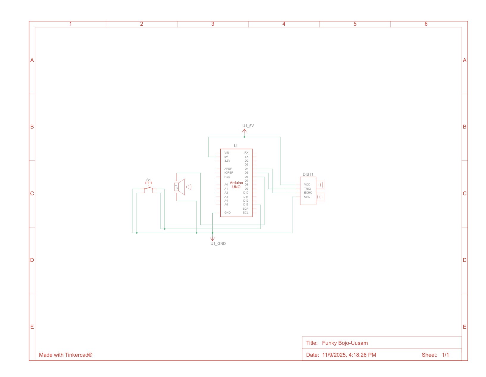
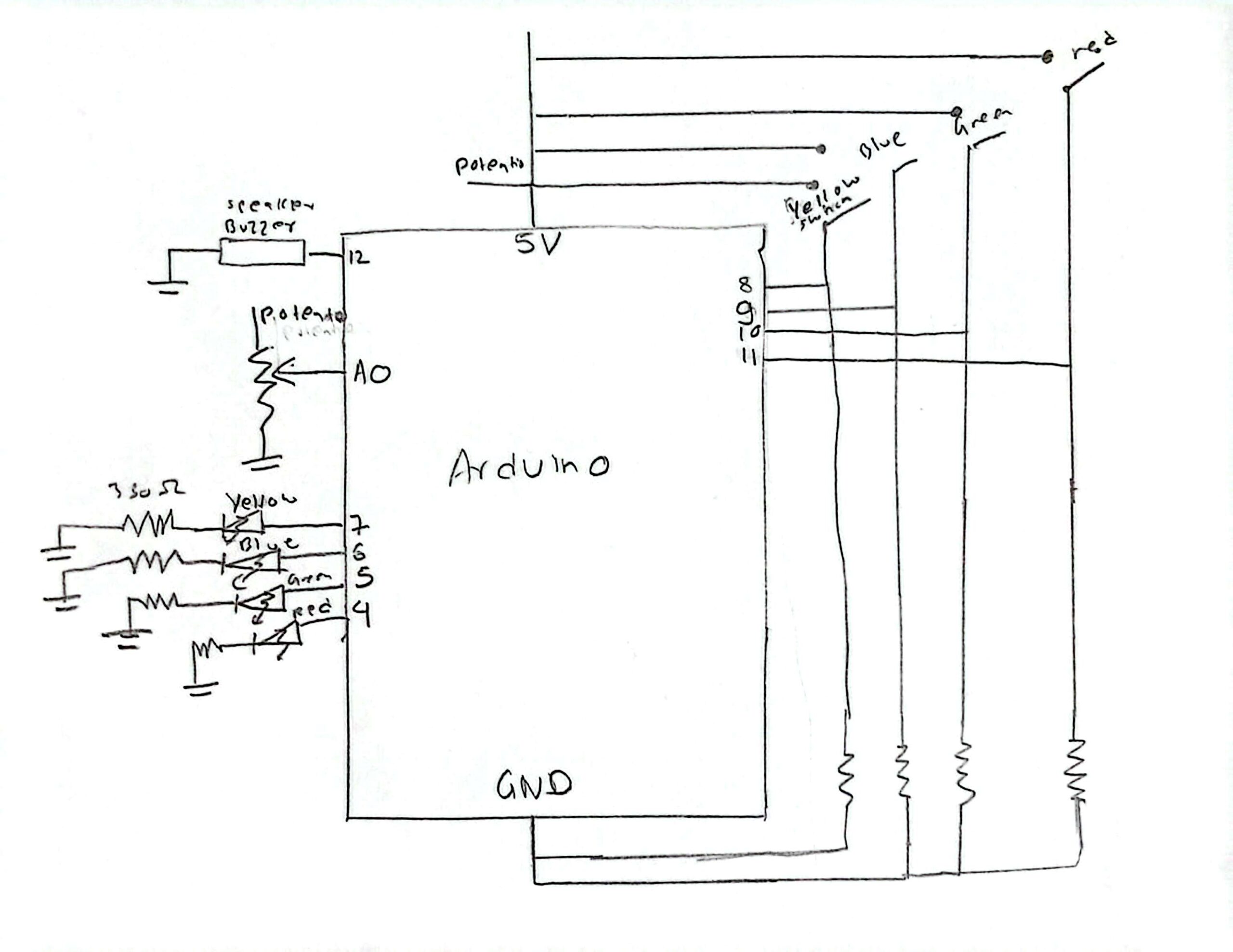
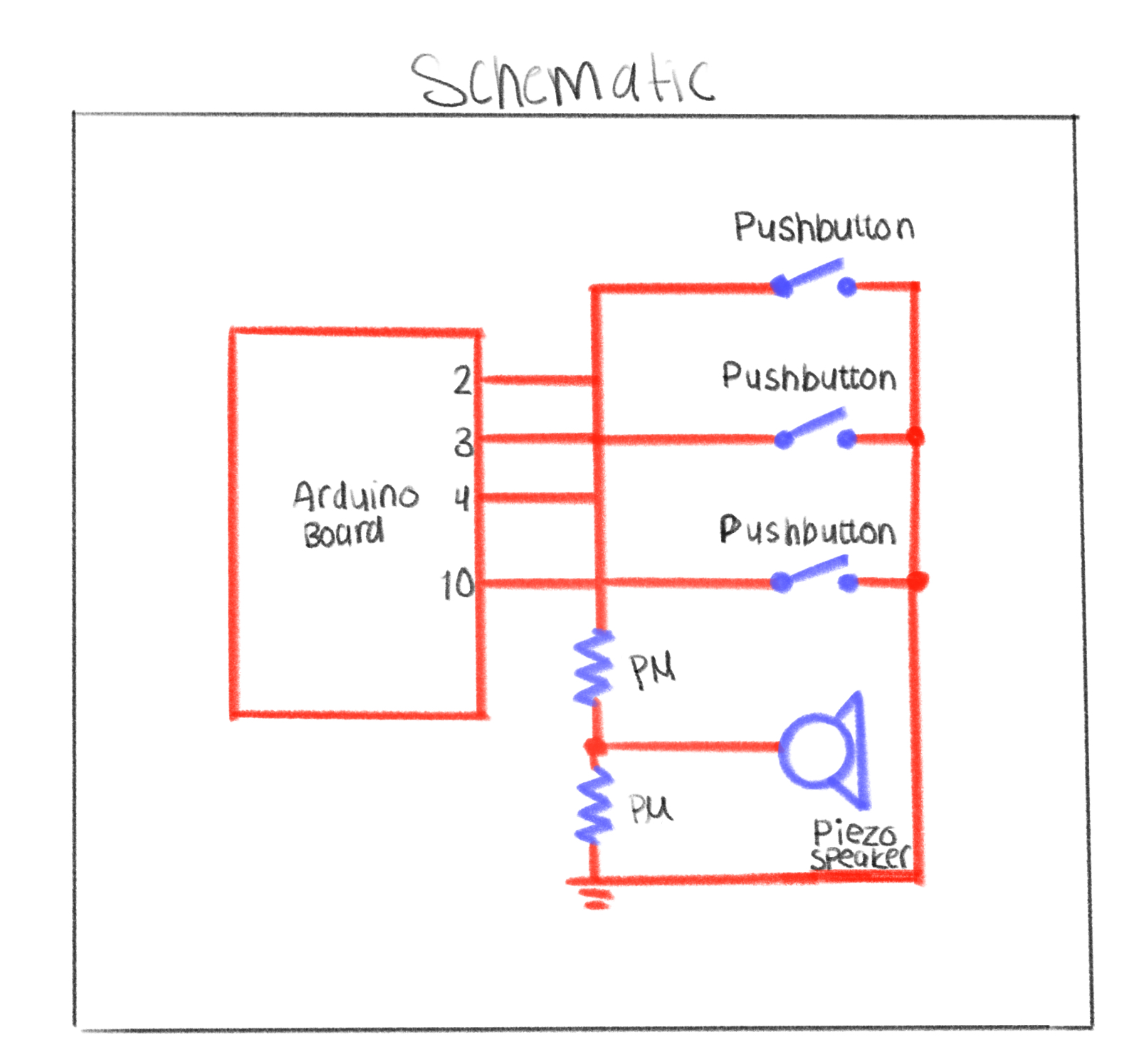
For this project, I decided to use three pushbuttons and a potentiometer because I wanted to keep the design simple but still interactive. My idea was to make the buttons act like keys—each one triggering a different tone on the piezo speaker. I also included the potentiometer to control the volume of the sound, which made the circuit more dynamic and gave me a sense of how analog and digital components can work together.
Designing the schematic was a fun and challenging part of the process. I had to carefully think about where each component should go and how to connect everything so it would be electrically correct. The piezo speaker was, of course, essential for producing sound it’s what brings the “instrument” to life.
What I enjoyed most was the problem-solving aspect figuring out how all the parts would communicate through the Arduino. It required patience and logical thinking, but once I understood the flow of current and how each input affects the output, it all made sense. Seeing the schematic come together gave me a real sense of accomplishment because it represented both my planning and my creativity.
Reflection on the Arduino Build
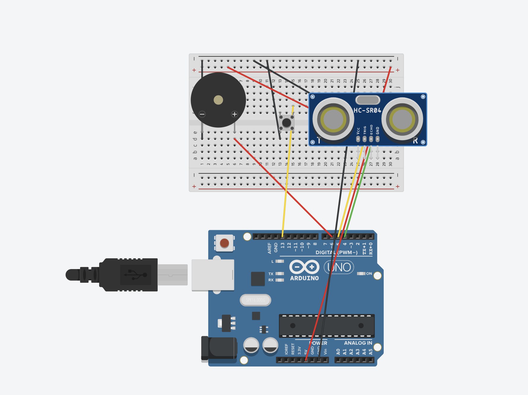
The Arduino part of this project was honestly very easy and smooth, especially because I had already planned everything out in my schematic. All I had to do was follow my own plan carefully and make sure that every wire and component was connected in the correct place.
One of the first things I did was connect the GND pin on the Arduino to the negative railon the breadboard. That allowed me to connect all my components that needed ground like the potentiometer, buttons, and piezo speaker to the same shared ground.
I had to be precise and double-check my connections, especially where the potentiometer linked to the speaker and where each button was wired. To make the process easier and more organized, I actually color-coded my wires. For example, I used red wires for all the connections that went to ground. That made it much simpler to trace the circuit visually and fix small mistakes when I needed to adjust something later.
Overall, the Arduino part went very smoothly because I had a solid plan and followed it carefully. Seeing everything come together and actually work just like I designed it in the schematic felt really rewarding.
//set the pins for the button and buzzer
int firstKeyPin = 2;
int secondKeyPin = 3;
int thirdKeyPin = 4;

int buzzerPin = 10;


void setup() {
  //set the button pins as inputs
  pinMode(firstKeyPin, INPUT_PULLUP);
  pinMode(secondKeyPin, INPUT_PULLUP);
  pinMode(thirdKeyPin, INPUT_PULLUP);

  //set the buzzer pin as an output
  pinMode(buzzerPin, OUTPUT);
}

void loop() {

  if(digitalRead(firstKeyPin) == LOW){        //if the first key is pressed
    tone(buzzerPin, 262);                     //play the frequency for c
  }
  else if(digitalRead(secondKeyPin) == LOW){  //if the second key is pressed
    tone(buzzerPin, 330);                     //play the frequency for e
  }
  else if(digitalRead(thirdKeyPin) == LOW){   //if the third key is pressed
    tone(buzzerPin, 392);                     //play the frequency for g
  }
  else{
    noTone(buzzerPin);                        //if no key is pressed turn the buzzer off
  }
}
Reflection on the Coding
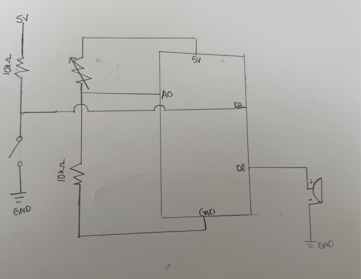
The coding part of this project was very straightforward. I already had my circuit ready, so I just needed to make sure that everything in my code matched the pins I used in my schematic and breadboard. I started by defining all of my pins clearly one for each of the three buttons and one for the piezo speaker.
I wanted each button to act as a different key, so I chose three different frequencies (in hertz) to create distinct sounds. I adjusted the hertz values to my liking until each key sounded right and had its own tone. This made the instrument feel more realistic and musical.
I also made sure to define all the variables and constants I needed in my code so that everything was organized and easy to change later if I wanted to experiment with new sounds or pin connections. Overall, the coding was simple but satisfying because it brought the entire project to lifethe schematic, the Arduino wiring, and the code all worked together perfectly.