Our Concept:
Our project drew inspiration from last week’s readings on human-computer interaction, particularly the ways in which technology can respond to subtle human behaviors. We explored how interactive systems often mediate our engagement with the environment and even with ourselves, creating experiences that feel responsive, social, or even playful.
With this perspective, we asked ourselves: what if an instrument didn’t just make sound, but responded directly to human behavior? Instead of rewarding interaction, it could intervene. Instead of passive engagement, it could create a performative, almost social response.
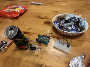
From this idea, the Diet Drum emerged — a device that reacts whenever someone reaches for a snack. The system is both humorous and relatable, externalizing the human struggle of self-control. When a hand approaches the snack bowl, a servo-powered drumstick strikes, accompanied by a short melody from a passive buzzer. The result is a playful, judgmental interaction that transforms a familiar, internal tension into an amusing and performative experience.
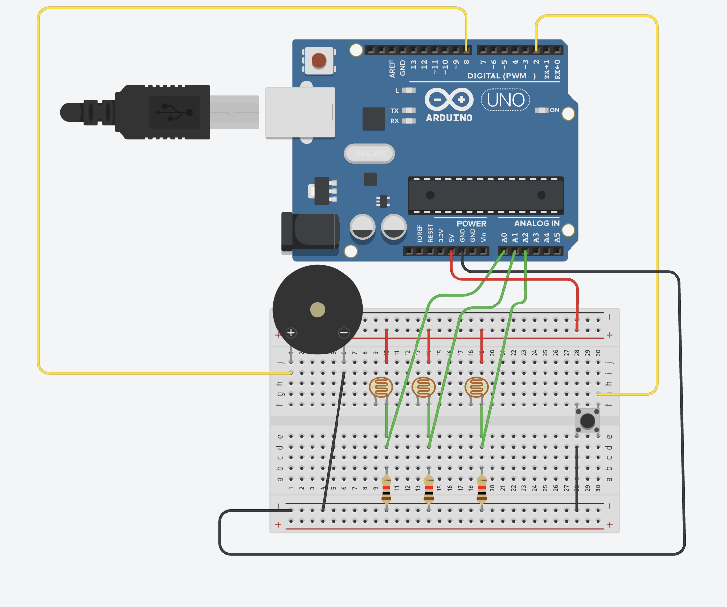
How It Works
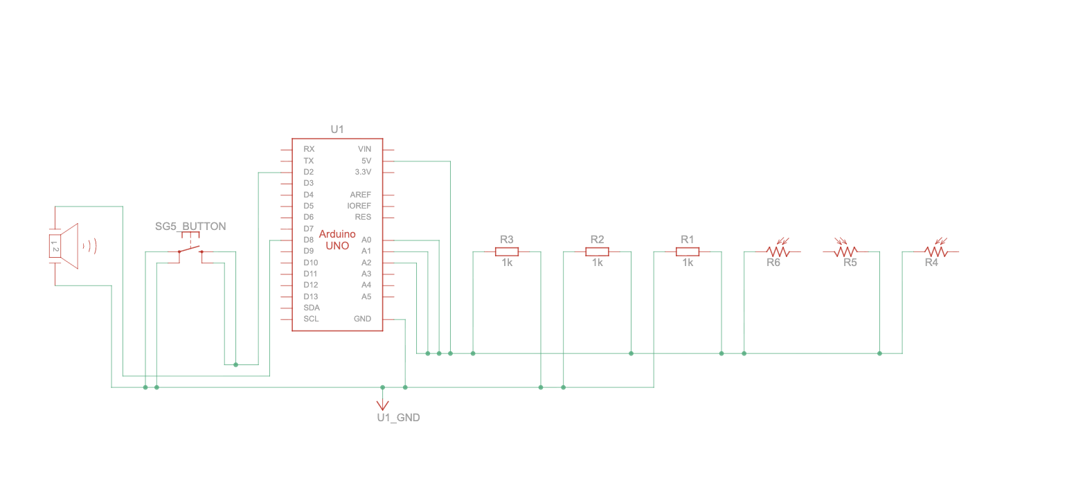
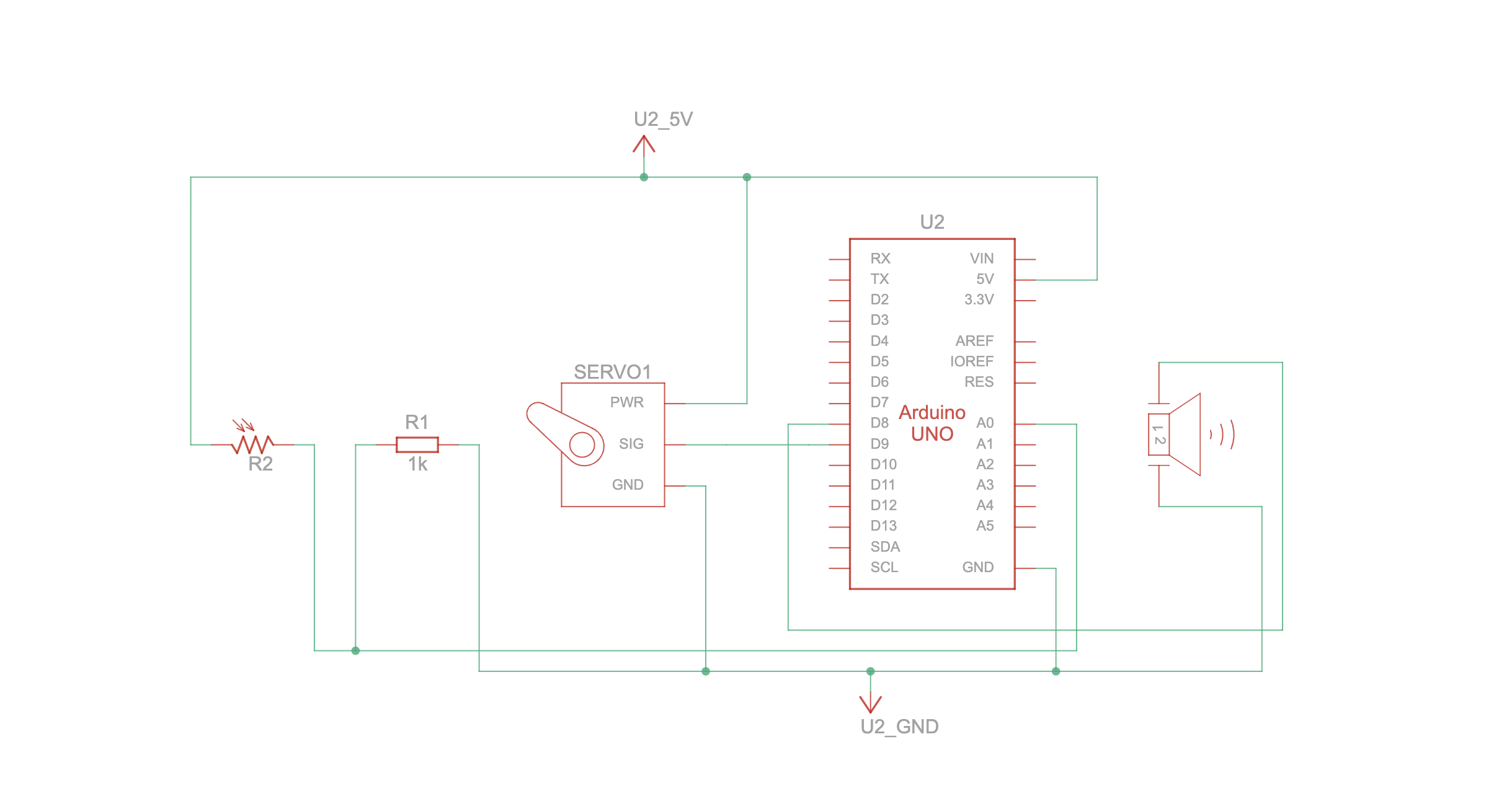
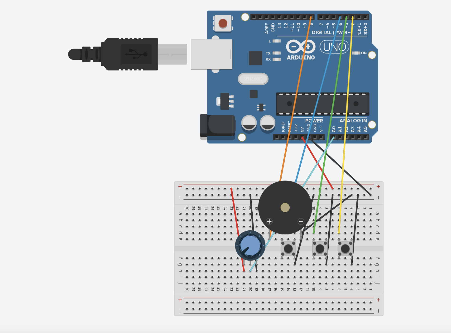
- Photoresistor (LDR): Detects hand movements by monitoring changes in light. As a hand blocks the sensor, the reading drops.
- Servo motor: Moves a drumstick to perform a percussive strike, physically reinforcing the “warning” aspect of the interaction.
- Passive buzzer: Plays a short melody as a playful, auditory cue.
Arduino Uno: Continuously monitors the sensor and triggers both motion and sound.
When the LDR senses that a hand has blocked the light, the Arduino makes the servo play the melody and hit the drum. This creates a clear, immediate connection between what a person does and how the system responds, showing ideas from our readings about how devices can react to gestures and sensor input.
Video Demonstration
assignment10

Challenges
Throughout development, we encountered several challenges that required both technical problem-solving and design fixing:
- System reliability: While the setup initially worked smoothly, leaving it for some time caused it to fail. Figuring out the problem took us some time because we didn’t know what went wrong and whether it was the setup or the code. So we had to partially rebuild and retune the system to restore functionality.
- Mechanical stability: Keeping the drumstick steady during strikes was more difficult than anticipated. Any slight movement or misalignment affected the accuracy and consistency of the strikes, requiring several adjustments.
- Audio timing: The melody initially played too long, delaying servo motion and disrupting the intended interaction. Shortening the audio ensured that the strike and sound remained synchronized, preserving the playful effect.
- We used AI, to help with some code difficulties we had, to fit with our original idea.
Code Highlights
One part of the code we’re especially proud of is how the sensor input is mapped to the servo’s movement.
float d = constrain(drop, MIN_DROP, MAX_DROP);
float k = (d - MIN_DROP) / float(MAX_DROP - MIN_DROP);
int hitAngle = SERVO_HIT_MIN + int((SERVO_HIT_MAX - SERVO_HIT_MIN) * k);
unsigned long downMs = STRIKE_DOWN_MS_MAX - (unsigned long)((STRIKE_DOWN_MS_MAX - STRIKE_DOWN_MS_MIN) * k);

strikeOnce(hitAngle, downMs);
This makes the drumstick respond based on how close the hand is, so each action feels deliberate rather than just an on/off hit. It lets the system capture subtle gestures, supporting our goal of reflecting nuanced human behavior.
Future Improvements
Looking forward, we see several ways to expand and refine the Diet Drum:
- Adaptive audio: Varying the melody or warning tone based on how close the hand is could enhance the playfulness and expressiveness.
- Mechanical refinement: Improving the stability of the drumstick and optimizing servo speed could create smoother strikes and more consistent feedback.
- Compact design: Reducing the size of the device for easier placement would make it more practical for everyday use.
- Visual cues: Adding optional LEDs or visual signals could enhance the feedback, making the system even more engaging.
Github Link:
https://github.com/deemaalzoubi/Intro-to-IM/blob/b321f2a0c4ebf566082f1ca0e0067e33c098537f/assignment10.ino
https://github.com/deemaalzoubi/Intro-to-IM/blob/b321f2a0c4ebf566082f1ca0e0067e33c098537f/pitches.h