My Concept
I decided to build a “two-degree safety guardrail.” The logic is based on two separate actions:
- Idle State: A red LED is ON (digital
HIGH). - “Armed” State: A button is pressed. This turns the red LED OFF (digital
LOW). - “Active” State: While the button is held, a FSR (force-sensing resistor) is pressed, which controls the brightness of a green LED (my analog output).
Challenge
My challenge was getting the red LED to be ON by default and turn OFF only when the button was pressed. I tried to build a hardware-only pull-up or bypass circuit for this but struggled to get it working reliably on the breadboard.
So, I shifted that logic into Arduino code adapted from a template in the IDE.
// constants won't change. They're used here to set pin numbers:
const int buttonPin = 2;  // the number of the pushbutton pin
const int ledPin = 13;    // the number of the LED pin

// variables will change:
int buttonState = 0;  // variable for reading the pushbutton status

void setup() {
  // initialize the LED pin as an output:
  pinMode(ledPin, OUTPUT);
  // initialize the pushbutton pin as an input:
  pinMode(buttonPin, INPUT);
}

void loop() {
  // read the state of the pushbutton value:
  buttonState = digitalRead(buttonPin);

  // check if the pushbutton is pressed. If it is, the buttonState is HIGH:
  if (buttonState == LOW) {
    // turn LED on:
    digitalWrite(ledPin, LOW);
  } else {
    // turn LED off:
    digitalWrite(ledPin, HIGH);
  }
}
The demo was shot with the Arduino implementation.
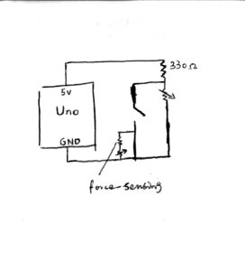
Schematic
However, I later figured out the pull-up logic, and was able to implement a hardware-only solution. This schematic was a result of the updated circuit.

