
I initially really struggled to come up with a concept for this week’s project. While I understood how to use analog and digital switches, I wasn’t sure how I would use them in conjunction to create something engaging and interesting. I slept on it and woke up with the idea to build off the theme of security from week 8 and make a lock mechanism using analog inputs like the potentiometer.
One of my biggest concerns was that I wasn’t sure how to draw a proper schematic so I looked online and used Tinkercad Circuits for a while but it wasn’t exactly the simple schematic drawing I wanted so I decided to save the site for future use instead.
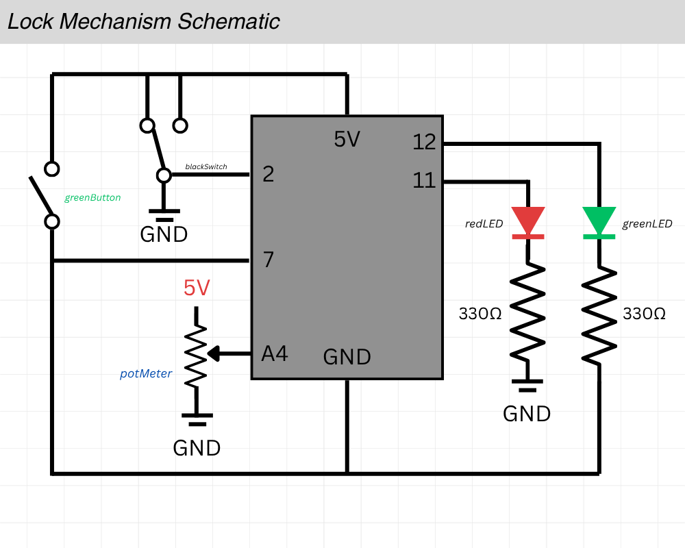
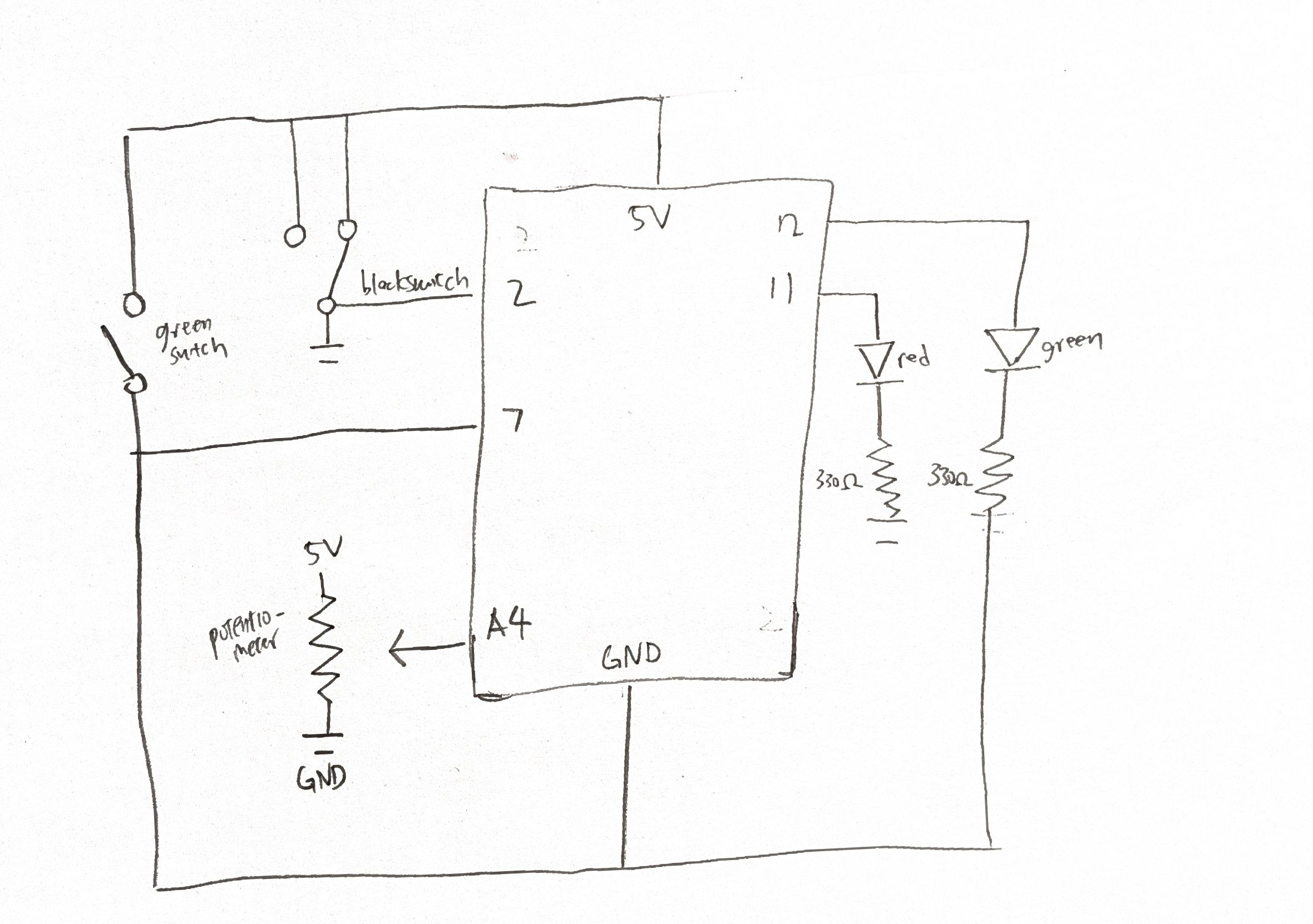
This was the schematic I came up with. I knew I was going to mess up and have to move stuff around so I did it digitally using simple shapes and lines on canvas. I barely knew what I was doing and to be honest it made a LOT more sense to just start putting wires and pieces together on the breadboard but this schematic was how I thought it would look.
And this is how it looked physically with all the relevant pieces attached to the breadboard.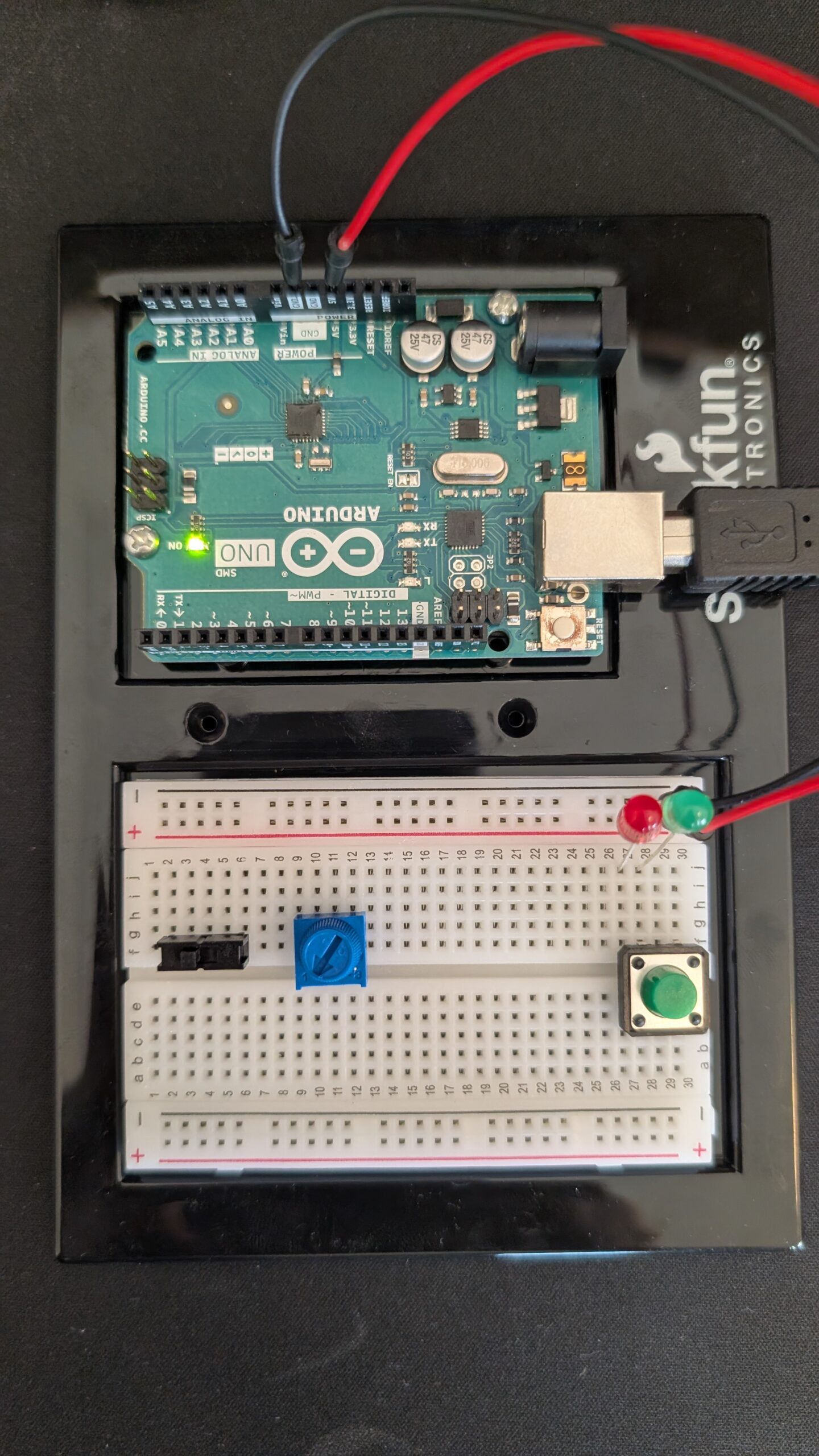
I knew the wiring would get pretty crazy as I started to connect everything so this is how I color-coded them:
-
- Red: Power Source (+)
- Black: Ground (-)
- Green: Inputs Connections to Arduino Uno (Switch, Pot Meter, etc)
- Yellow: Output Connections to Arduino Uno (LEDs)
On the code-side, I made sure to declare each pin I was going to use at the very top so I could quickly change it if I needed to swap stuff around.
int greenButton = 7; //button to open lock
int blackSwitch = 2; //part of the lock (the black on/off switch)
int potMeter = A4; //part of the lock (the roating blue one)

int greenLED = 12; //lock is open
int redLED = 11; //indicates lock is still locked

//LOCK COMBINATIONS
int blackSwitchANSWER = LOW;
int potMeterANSWER = 1000; //above X value to be correct
This is what the final product looked like: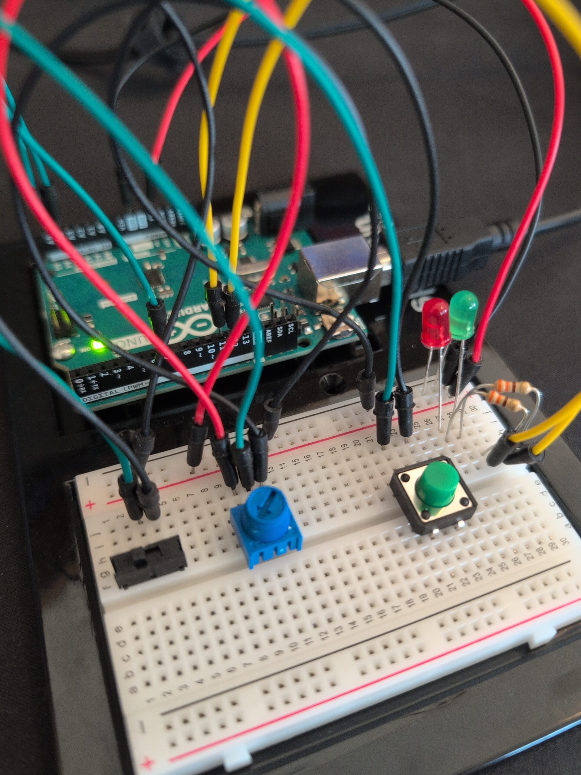
I didn’t run into many bugs when coding but I did initially accidentally set the red light to always be on unless I was holding down the green button. I had to search online how I could fix this and I eventually found I could set the pinmode for the button to “INPUT_PULLUP” which was useful for inputs that otherwise would have no stable value when not pressed.
pinMode(greenButton, INPUT_PULLUP); //INPUT_PULLUP is good for buttons that automatically spring back uppinMode(blackSwitch, INPUT_PULLUP);
pinMode(potMeter, INPUT);

pinMode(greenLED, OUTPUT);
pinMode(redLED, OUTPUT);
I did have a physical difficulty where I was testing different kinds of inputs with the switch and the potentiometer and forgot what the correct combination actually was– and with no way to know if the green light was even going to turn on when it WAS correct. Thankfully a minute of trial and error and making sure the code side of things was correct got me to return to the original combination, but that could’ve been pretty annoying if the lock was any more complicated.
When it came to the LED light responses. I originally had the appropriate light turn on for 2 seconds and then turn off. I felt like this didn’t feel quite right so I made a creative decision to flash the appropriate light as feedback instead; I did this by creating a for loop that would flash the light 5 times with a small delay. This felt a LOT more responsive than the brief moment that the light would turn on previously. Below is the full if-statement that checked whether the confirm button, the green one, was pressed.
if (greenButtonState == LOW) {
  if (LockIsUNLOCKED == true) {
    digitalWrite(redLED, LOW); //turn OFF red light
    for(int i = 0; i < 5; i++) {    // flash 5 times
      digitalWrite(greenLED, HIGH);
      delay(150);
      digitalWrite(greenLED, LOW);
      delay(150);
    }

  } else {
    digitalWrite(greenLED, LOW); //turn OFF green light
    for(int i = 0; i < 5; i++) {    // flash 5 times
      digitalWrite(redLED, HIGH);
      delay(150);
      digitalWrite(redLED, LOW);
      delay(150);
    }
  }
}
I am very proud of how it turned out in the end with both the technical difficulties that I solved and how it feels to interact with it. Below is a demonstration of the lock working; you need to toggle the black switch to the right side and twist the potentiometer counterclockwise to the end.
Link to ino File (Google Drive)