-
-
- Describe your concept
- My concept is a musical controller. With the inputted song, users can use potentiometers and proximity sensors to control different aspects of the sound such as reverb and delay. On the p5 end, there is a spectral music visualizer where you can see the volume of each band (section of frequencies) across the sketch. There is also a sound visualizer cat, modelled after my arduino cat, that moves with the music.
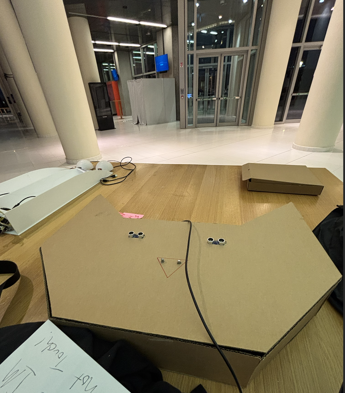
- Include some pictures / video of your project interaction
- How does the implementation work?
-
- Description of interaction design
- The user moves their hand over the sensors to control reverb and delay, and distortion in the sound . The knobs can be used to manipulate pitch and filter of the sound
- Description of Arduino code and include or link to full Arduino sketch
/* * created by Rui Santos, https://randomnerdtutorials.com * * Complete Guide for Ultrasonic Sensor HC-SR04 * Ultrasonic sensor Pins: VCC: +5VDC Trig : Trigger (INPUT) - Pin11 Echo: Echo (OUTPUT) - Pin 12 GND: GND */ int potPinA = A1; int potPinB = A2; int trigPinA = 8; // Trigger int echoPinA = 9; // Echo int trigPinB = 10; // Trigger int echoPinB = 11; // Echo int potValA; int potValB; int prevSenValA; int prevSenValB; long durationA; long durationB; long cma, cmb, inches; void setup() { //Serial Port begin Serial.begin (9600); //Define inputs and outputs pinMode(potPinA,INPUT); pinMode(potPinB,INPUT); pinMode(trigPinA, OUTPUT); pinMode(echoPinA, INPUT); pinMode(trigPinB, OUTPUT); pinMode(echoPinB, INPUT); } void loop() { // The sensor is triggered by a HIGH pulse of 10 or more microseconds. // Give a short LOW pulse beforehand to ensure a clean HIGH pulse: digitalWrite(trigPinA, LOW); delayMicroseconds(5); digitalWrite(trigPinA, HIGH); delayMicroseconds(10); digitalWrite(trigPinA, LOW); potValA = analogRead(potPinA); potValB = analogRead(potPinB); // Read the signal from the sensor: a HIGH pulse whose // duration is the time (in microseconds) from the sending // of the ping to the reception of its echo off of an object. pinMode(echoPinA, INPUT); durationA = pulseInLong(echoPinA, HIGH); digitalWrite(trigPinB, LOW); delayMicroseconds(5); digitalWrite(trigPinB, HIGH); delayMicroseconds(10); digitalWrite(trigPinB, LOW); pinMode(echoPinB, INPUT); durationB = pulseInLong(echoPinB, HIGH); // Convert the time into a distance cma = (durationA/2) / 29.1; cmb = (durationB/2) / 29.1; // Divide by 29.1 or multiply by 0.0343 if(cma < 500) { prevSenValA = cma; } else { cma = prevSenValA; } if(cmb < 500) { prevSenValB = cmb; } else { cmb = prevSenValB; } Serial.print(cmb); Serial.print(", "); Serial.print(cma); Serial.print(", "); Serial.print(potValB); Serial.print(", "); Serial.print(potValA); Serial.println(); delay(50); } - Schematic of your circuit (hand drawn or using tool)
- also here:
- Description of p5.js code and embed p5.js sketch in post
- Description of communication between Arduino and p5.js
-
- Will use serial communication, with arduino outputting a list at interval. it will be in the form of [sensor 1 distance],[sensor 2 distance],[pot 1 value],[pot 2 val]. This list will be picked up by p5.
-
-
- What are some aspects of the project that you’re particularly proud of?
- the shell design and Arduino code. It took me a long time to learn how to use two sensors in succession on the same Arduino. Other than that, I think using the fft to do the spectrum visualizer was something I am proud of.
- What are some areas for future improvement?
- I could definitely have more moving components, and more ways to modulate the audio signal. Also, one of the sensors kept malfunctioning, so making the overall structure and making it more stable (acrylic box or something) to make it a proper music device. Next time too, make my music thing be able to pick diffferent songs
- Describe your concept
-
Skip to content