Week 11: Serial Communication

Group Members: Maliha Nahiyan Srotosshini & Shamsa Alremeithi

Exercise 1

task: make something that uses only one sensor on arduino and makes an ellipse (or other shape) in p5 move on the horizontal axis, in the middle of the screen, and nothing on arduino is controlled by p5

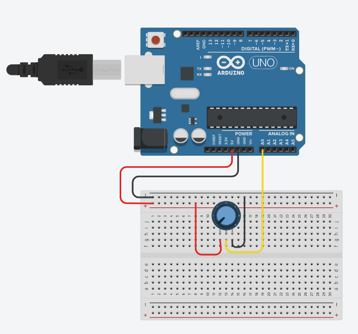
For this exercise, we had connected a potentiometer to the Arduino by connecting the middle pin to analog pin A1, and the other two pins to 5V and GND. we had written a simple Arduino code to read the analog value from the potentiometer and map it to a range of 0 to 400, which was then sent to the computer through the serial port. With p5.js and the p5.webserial library, a circle moves left to right across the screen based on the potentiometer’s position. we also included “Connect” and “Disconnect” buttons to control the serial connection from the browser with ease.

arduino code
void setup() {
  Serial.begin(9600);  // Initialize serial communication at 9600 baud rate
}

void loop() {
  // Read the analog value from pin A1 (range: 0 to 1023)
  int potentiometer = analogRead(A1);

  // Map the potentiometer value (0-1023) to a new range (0-400)
  int mappedPotValue = map(potentiometer, 0, 1023, 0, 400);

  // Send the mapped value to p5.js via serial
  Serial.println(mappedPotValue);

  delay(100);  // Wait for 100 milliseconds before the next reading
}
); }
P5.js code
let port;
let connectBtn;
let disconnectBtn;
let baudrate = 9600;
let isConnected = false;

function setup() {
  createCanvas(400, 400);
  background(220);

  // Create a new Web Serial port instance using p5.webserial
  port = createSerial();

  // If a port was previously used, auto-connect to it
  let usedPorts = usedSerialPorts();
  if (usedPorts.length > 0) {
    port.open(usedPorts[0], baudrate);
    isConnected = true;
  }

  // Create the Connect button and open the port when clicked
  connectBtn = createButton("Connect to Serial");
  connectBtn.position(10, 10);
  connectBtn.mousePressed(() => {
    port.open(baudrate); // Opens a serial connection using the chosen baud rate
    isConnected = true;
  });

  // Create the Disconnect button to close the serial port
  disconnectBtn = createButton("Disconnect");
  disconnectBtn.position(150, 10);
  disconnectBtn.mousePressed(() => {
    port.close(); // Closes the serial connection
    isConnected = false;

    // Clear screen and show "Disconnected" message
    background(255);
    textAlign(CENTER, CENTER);
    textSize(18);
    fill(100);
    text("Disconnected.", width / 2, height / 2);
  });
}

function draw() {
  if (isConnected) {
    // Read until newline character
    let str = port.readUntil("\n");

    if (str.length > 0) {
      background("white");

      // Convert the received string to an integer (e.g., mapped potentiometer value)
      let x = int(str);

      // Make sure x stays within the canvas width (safety measure)
      x = constrain(x, 0, width);

      // Draw an ellipse at the position based on incoming data
      ellipse(x, 200, 40, 40);
    }
  }
}

Excercise 2

task:
make something that controls the LED brightness from p5

p5.js interface:

Arduino Code:
int ledPin = 9; // PWM-capable pin to control LED brightness

void setup() {
  Serial.begin(9600);          // Start serial communication at 9600 baud rate
  pinMode(ledPin, OUTPUT);     // Set the LED pin as an output
}

void loop() {
  if (Serial.available()) {    // Check if data is available to read from serial
    int brightness = Serial.parseInt();  // Read the integer value (brightness)
    brightness = constrain(brightness, 0, 255); // Limit the value to the 0-255 range
    analogWrite(ledPin, brightness);   // Write the brightness value to the LED pin
  }
}

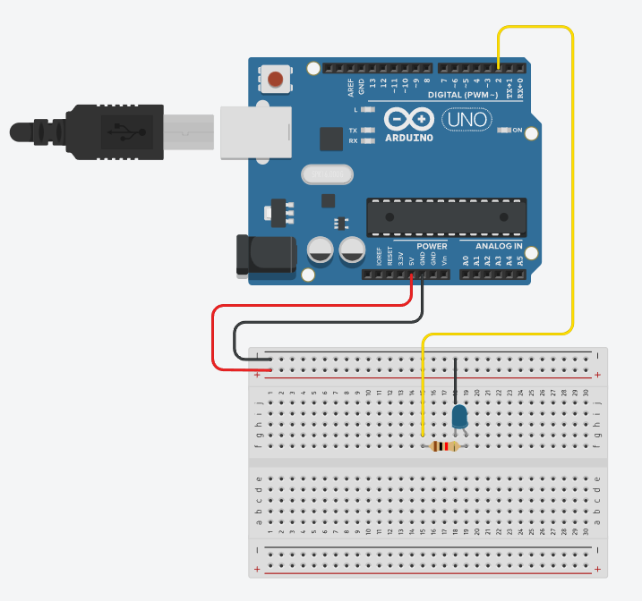
This project creates a real-time visual and physical interface to control an LED’s brightness using a slider in a p5.js sketch. The brightness value is sent from the browser to an Arduino board via serial communication. As the user moves the slider, the LED’s intensity changes accordingly, both in the physical circuit and on-screen through a glowing animation and gauge ring. The interface also includes a connect/disconnect button for flexible hardware control.

Excercise 3

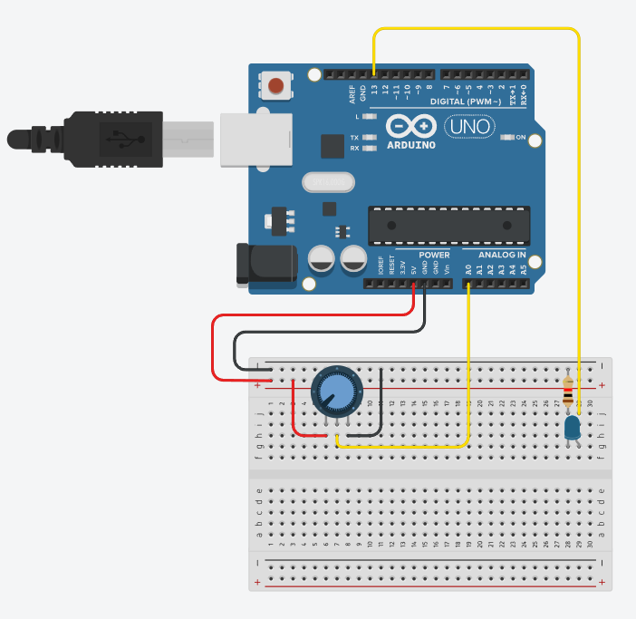
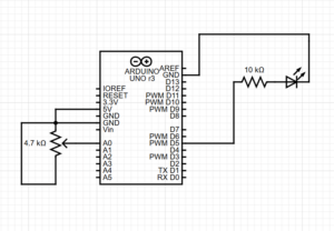
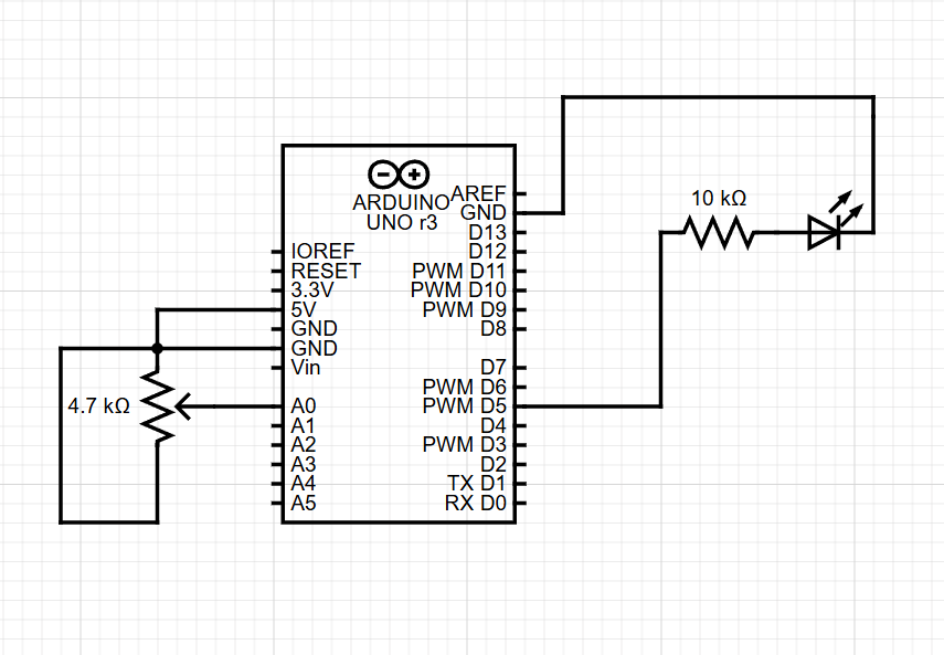
In this exercise, we took the gravity and wind example and instead connected it to the Arduino. We replaced the digital wind control with a potentiometer, allowing us to control the wind force by hand. Additionally, we used an LED to light up every time the ball hit the ground and is at rest.

Arduino Code:
// Define the pin connected to the LED
const int ledPin = 5;

// Define the analog pin connected to the potentiometer
const int potPin = A0;

void setup() {
  // Start serial communication at 9600 baud
  Serial.begin(9600);

  // Set the LED pin as an output
  pinMode(ledPin, OUTPUT);
}

void loop() {
  // Read the analog value from the potentiometer
  int sensorValue = analogRead(potPin);

  // Print the sensor value to the Serial Monitor
  Serial.println(sensorValue);

  // Check if data is available to read from the Serial Monitor
  if (Serial.available() > 0) {
    // Read the incoming character
    char msg = Serial.read();

    // If the received character is '1', turn on the LED
    if (msg == '1') {
      digitalWrite(ledPin, HIGH);
    }
    // If the received character is '0', turn off the LED
    else if (msg == '0') {
      digitalWrite(ledPin, LOW);
    }

    // Clear any extra characters in the serial buffer
    while (Serial.available() > 0) {
      Serial.read();
    }
  }

  // Small delay to avoid flooding the serial output
  delay(50);
}

p5.js Code:

let port;
let baudrate = 9600;
let position, velocity, acceleration, gravity, wind;
let drag = 0.99;
let mass = 50;
let val = 0;
let str = "";
let hitGround = false;

function setup() {
  createCanvas(640, 360);
  noFill();

  position = createVector(width / 2, 0);
  velocity = createVector(0, 0);
  acceleration = createVector(0, 0);
  gravity = createVector(0, 0.5 * mass);
  wind = createVector(0, 0);

  port = createSerial();

  let connectButton = createButton("Connect");
  connectButton.position(10, 10);
  connectButton.mousePressed(() => {
    if (!port.opened()) port.open(baudrate);
  });

  let disconnectButton = createButton("Disconnect");
  disconnectButton.position(100, 10);
  disconnectButton.mousePressed(() => {
    if (port.opened()) port.close();
  });

  let dropButton = createButton("Drop Ball");
  dropButton.position(220, 10);
  dropButton.mousePressed(dropBall);
}

function draw() {
  background(255);

  applyForce(gravity);
  applyForce(wind);

  velocity.add(acceleration);
  velocity.mult(drag);
  position.add(velocity);
  acceleration.mult(0);

  ellipse(position.x, position.y, mass, mass);

  if (position.y > height - mass / 2) {
    velocity.y *= -0.9;
    position.y = height - mass / 2;

    if (!hitGround) {
      hitGround = true;
      if (port.opened()) {
        port.write("1\n"); // turn LED on
      }
    }
  } else {
    hitGround = false;
    if (port.opened()) {
      port.write("0\n"); // turn LED off
    }
  }

  str = port.readUntil("\n");
  val = int(str.trim());

  if (!isNaN(val)) {
    updateWind(val);
  }
}

function applyForce(force) {
  let f = p5.Vector.div(force, mass);
  acceleration.add(f);
}

function updateWind(val) {
  wind.x = map(val, 0, 1023, -1, 1);
}

function dropBall() {
  // Reset ball to the top
  position.y = 0;
  velocity.set(0, 0);
  acceleration.set(0, 0);
  hitGround = false;

  // Force LED off
  if (port.opened()) {
    port.write("0\n");
  }
}

SCHEMATIC

SchematiC


P5.js Artwork

Video

Link: https://drive.google.com/file/d/1bVrW1jPjtYBfAijWJPNHeHTnERkzNfPb/view?usp=sharing

Serial Communication

Arduino & p5.js

[Genesis and Nikita]

Each exercise focuses on the communication between the Arduino’s physical components and visual output through serial communication.


Exercise 1: Moving an Ellipse with One Sensor

video

Arduino Code:

void setup(){
 Serial.begin(9600);
}
void loop(){
 int pot = analogRead(A0);
 // send mapped X (0–400) to p5
 int xPos = map(pot, 0, 1023, 0, 400);
 Serial.println(xPos);
 delay(30);
}

circuit:

Explanation:

This exercise uses a single analog sensor (potentiometer) connected to Arduino to control the horizontal position of an ellipse in p5.js. The Arduino reads the potentiometer value and sends it over Serial to the p5.js sketch, which updates the x-position of the ellipse accordingly. The communication is one-way:   Arduino → p5.js.


Exercise 2: Controlling LED Brightness from p5.js

video

Arduino Code:

// Arduino: LED brightness via Serial.parseInt()
const int ledPin = 9; // PWM-capable pin


void setup() {
 pinMode(ledPin, OUTPUT);
 Serial.begin(9600); 
}


void loop() {
 if (Serial.available() > 0) {
   int brightness = Serial.parseInt(); // Read integer from serial
   brightness = constrain(brightness, 0, 255); // Clamp
   analogWrite(ledPin, brightness);
 }
}

circuit:

Explanation:

In this exercise, the communication is reversed. The p5.js sketch sends a brightness value (0–255) to Arduino via Serial, which adjusts the brightness of an LED connected to a PWM-capable pin (pin 9). This demonstrates real-time control from software (p5.js) to hardware (Arduino).


Exercise 3: Gravity Wind with LED Bounce Indicator

video

Arduino Code:

/*
* Exercise 3 Arduino:
* - Read pot on A0, send sensorValue to p5.js
* - Listen for 'B' from p5.js → blink LED on pin 9
*/
const int sensorPin = A0;
const int ledPin    = 9;


void setup() {
 Serial.begin(9600);       
 pinMode(ledPin, OUTPUT);
}


void loop() {
 // Read and send sensor
 int sensorValue = analogRead(sensorPin);
 Serial.println(sensorValue);


 // Check for bounce command
 if (Serial.available() > 0) {
   char inChar = Serial.read();
   if (inChar == 'B') {
     digitalWrite(ledPin, HIGH);
     delay(100);
     digitalWrite(ledPin, LOW);
   }
 }


 delay(20);
}

circuit:

Explanation:

This sketch is a modified version of the classic p5.js Gravity + Wind example. An analog sensor (potentiometer) on Arduino controls the wind force in p5.js. Every time the ball hits the bottom (a “bounce”), p5.js sends a command (‘B’) back to Arduino via Serial, which briefly lights up an LED. This showcases a complete two-way communication system between Arduino and p5.js.


Final Project Proposal

For my proposal, I was very inspired by the musical instrument assignment Hoor and I did for week 10. The 4 key piano model we made with cardboard, copper tape, and lots of alligator clips did not survive until it was time to present in class which really made me more passionate about creating a working model that not only looked good but also withstood multiple tests. Secondly, I was also inspired by one of my favorite games, Piano Tiles, where players must quickly tap moving piano keys in sync with a tune before they disappear off-screen. Combining both inspirations, my idea is to create a sturdy, fully functional four-key piano connected to an Arduino. Users will be able to physically play the game using this piano, while the gameplay will be displayed on a laptop screen and recreated in p5.js, complete with special effects such as power-ups and musical variations. I’m not quite sure what my plan is for actually building this new model, I am considering maybe 3d printing it or trying to see if I can find examples of 4 key piano models online.

Week 11: Serial Communication Assignment [Izza and Hoor]

For this assignment, Hoor and I worked together to do the 3 tasks.

Task 1: 

For this task, we used a potentiometer to control whether the ellipse was moving to the left or the right on the horizontal axis. We did this by mapping the values of the potentiometer (0-1023) on the horizontal axis. Then, when we turned the potentiometer the value would translate to a position on the horizontal axis that the ball would move to. We had some difficulties with the delay between the arduino and p5js as sometimes we’d have to wait a couple seconds before the code would update in p5. Here is the code for the arduino:

void setup() {
  Serial.begin(9600);
}

// Read potentiometer value (0–1023) and sends to p5js
void loop() {
  int sensorValue = analogRead(A0);
  Serial.println(sensorValue);
  delay(1);
}

Here is the p5js sketch:

Task 2:

For this task, we had to do something that controlled the brightness of an LED on the arduino breadboard through p5js. So, we decided to create a dropdown for the user to pick between 1-10 to control the brightness of the LED with 1 being off and 10 being maximum brightness. We then mapped that to the 0-255 range for the brightness of an LED and sent that to the arduino which would control how brightly the LED would light up for a few seconds. On the arduino we simply had one bulb connected to digital pin 9. The arduino code can be seen below:

void setup() {
  Serial.begin(9600);
  pinMode(9, OUTPUT);
}

//gets the serial converted value from p5js
void loop() {
  if (Serial.available() > 0) {
    int brightness = Serial.parseInt(); 
    brightness = constrain(brightness, 0, 255); //make sure the value isn't out of range
    analogWrite(9, brightness);
  }
}

Here is the p5js sketch:

Task 3:

In this task, we had to take already existing code and alter it such that every time the ball bounced, one LED light on the arduino lit up, and the wind was controlled by an analog sensor. For controlling our wind, we used a potentiometer once again as we could make it such that values above 512 would move the ball to the east (right) and values below 512 would move the ball towards the west (left). On the arduino, we connected a potentiometer at analog pin A0 and an LED light on digital pin 9. We then used p5js to receive that serial input from the potentiometer and map it to the wind. Whether it bounced being true or false is also what makes the LED light up. Once again, we did experience a delay between the potentiometer value and the wind in p5. The arduino code can be seen below:

const int potPin = A0;
const int ledPin = 9;
bool ledOn = false;
unsigned long ledTimer = 0;
const int ledDuration = 100;

void setup() {
  Serial.begin(9600);
  pinMode(ledPin, OUTPUT);
}

void loop() {
  // Read potentiometer and send value
  int potValue = analogRead(potPin);
  Serial.println(potValue);

  // If LED was turned on recently, turn it off after some time
  if (ledOn && millis() - ledTimer > ledDuration) {
    digitalWrite(ledPin, LOW);
    ledOn = false;
  }

  // recieve signal on whether the ball bounced from p5.js
  if (Serial.available()) {
    String input = Serial.readStringUntil('\n');
    input.trim();

    if (input == "bounce") {
      digitalWrite(ledPin, HIGH);
      ledOn = true;
      ledTimer = millis();
    }
  }

  delay(10); // Slight delay for stability
}

Here is the p5js sketch:

Lastly, here is the link to the video showing the LED light up and the ball being “blown” away by the value sent from the potentiometer:

https://drive.google.com/file/d/140pGv-9DMPd1gCa1xMn_LR3pR_pphx47/view?usp=sharing

Assignment 11: Serial Communication

For this week’s assignment, we were asked to complete the three examples we had been tasked with during class. This week’s work was a learning curve on its own. It took a while to get the hang of connecting P5.js and Arduino together after using them both as seperate entities, but seeing them connected was really exciting.

Task 1 – make something that uses only one sensor on Arduino and makes the ellipse in p5 move on the horizontal axis

For this task, I used a potentiometer to get analogue values, then mapped them onto my P5 canvas to make the ellipse move

P5 code:

let serial; // variable for the serial object
let latestData = "waiting for data"; // variable to hold the data

function setup() {
  createCanvas(400, 400);
  // serial constructor
  serial = new p5.SerialPort();

  // serial port
  serial.open('COM6');

  // what to do when we get serial data
  serial.on('data', gotData);

}

// when data is received in the serial buffer

function gotData() {
  let currentString = serial.readLine(); // store the data in a variable
  trim(currentString); // get rid of whitespace
  if (!currentString) return; // if there's nothing in there, ignore it
  console.log(currentString); // print it out
  latestData = currentString; // save it to the global variable
}

function draw() {
  background(255, 255, 255);
  fill(0, 0, 0);
  text(latestData, 10, 10); // print the data to the sketch

  // using the recieved data to change the x value of the circle 
  let moveHorizontal = map(latestData, 0, 1023, 0 , width);
  ellipse(moveHorizontal, height/2, 100, 100);


}

Arduino code:

const int ledPin = 3;      // the pin that the LED is attached to

void setup() {
  // initialize the serial communication:
  Serial.begin(9600);
  // initialize the ledPin as an output:
  pinMode(ledPin, OUTPUT);
}

void loop() {
  int brightness;

  // check if data has been sent from the computer:
  if (Serial.available() > 0) {
    // read the most recent byte (which will be from 0 to 255):
    brightness = Serial.read();
    // set the brightness of the LED:
    analogWrite(ledPin, brightness);
  }
}

Arduino schematic:

Task 2 – make something that controls the LED brightness from P5

For this task, I created a gradient background on P5, then used the mouseDragged() function to map it onto the LED connected on the Arduino

P5 code:

let serial; // variable for the serial object
let bright = 0; // variable to hold the data we're sending
let dark, light; // variables to hold the bgcolor

function setup() {
  createCanvas(512, 512);
  // colors for a blue gradient
  dim = color(0, 191, 255 );  // light blue
  bright = color(0, 0, 128);  // dark blue

  // serial constructor
  serial = new p5.SerialPort();

  // serial port
  serial.open('COM6');
}

function draw() {
  // Create a vertical blue gradient
  for (let y = 0; y < height; y++) {
    // Directly map the y position to the blue color
    let c = map(y, 0, height, dim.levels[2], bright.levels[2]);  // Map blue values from dark to light
    stroke(c, c, 255);  // Set color to blue, vary based on y position
    line(0, y, width, y);
  }

  stroke(255);
  strokeWeight(3);
  noFill();
  ellipse(mouseX, mouseY, 10, 10);
}

function mouseDragged() { // mapping the brightness level based on the position of the mouse
  brightLevel = floor(map(mouseY, 0, 512, 0, 255));
  // ensuring the brightness level does not exceed the level possible for the LED
  brightLevel = constrain(brightLevel, 0, 255);
  serial.write(brightLevel);
  console.log(brightLevel);
}

Arduino code:

const int ledPin = 13;  // Pin where the LED is connected
const int windSensorPin = A0;  // Pin for the analog wind sensor
int sensorValue = 0;

void setup() {
  pinMode(ledPin, OUTPUT);  // Set LED pin as an output
  Serial.begin(9600);  // Start serial communication
}

void loop() {
  // Check if there is incoming serial data
  if (Serial.available() > 0) {
    char incomingByte = Serial.read();  // Read incoming byte

    if (incomingByte == 'O') {
      digitalWrite(ledPin, HIGH);  // Turn LED ON
    } else if (incomingByte == 'F') {
      digitalWrite(ledPin, LOW);  // Turn LED OFF
    }
  }

  // Read the wind sensor value (adjust if needed)
  sensorValue = analogRead(windSensorPin);
  // Optionally, print the sensor value for debugging
  Serial.println(sensorValue);
  delay(100);
}

Arduino schematic:

Task 3 – take the gravity wind example (https://editor.p5js.org/aaronsherwood/sketches/I7iQrNCul) and make it so every time the ball bounces one led lights up and then turns off, and you can control the wind from one analog sensor

For this task, I used a potentiometer on the Arduino to send analogue values for the wind in the P5 example. I struggled with having the LED light up in time with the ball bounces, but I ended up using an IF statement within the draw() function which would then send a HIGH or LOW voltage value back to the Arduino

P5 code:

let velocity;
let gravity;
let position;
let acceleration;
let wind;
let drag = 0.99;
let mass = 50;

// new variables added
let windSensorValue = 0;
let serial; 
let latestData = "0"; 
let ledState = false; // true = on, false = off

function setup() {
  createCanvas(640, 360);
  noFill();
  position = createVector(width / 2, 0);
  velocity = createVector(0, 0);
  acceleration = createVector(0, 0);
  gravity = createVector(0, 0.5 * mass);
  wind = createVector(0, 0);

  // setting up the serial port
  serial = new p5.SerialPort();
  serial.open('COM6'); 
  serial.on('data', serialEvent);
}
// Arduino data is stored inside the variable latestData
function serialEvent() {
  let incoming = serial.readLine();
  if (incoming.length > 0) {
    latestData = incoming; 
  }
}

function draw() {
  background(255);

  // reading the Potentiometer value
  // mapping the potentiometer value to wind (either left or right)
  let sensorValue = int(latestData);
  wind.x = map(sensorValue, 0, 1023, -5, 5);

  applyForce(wind);
  applyForce(gravity);
  velocity.add(acceleration);
  velocity.mult(drag);
  position.add(velocity);
  acceleration.mult(0);

  ellipse(position.x, position.y, mass, mass);

  // Ball hitting ground
  if (position.y >= height - mass / 2) {
    position.y = height - mass / 2;
    velocity.y *= -0.9;

    // If touching ground and LED not already on
    if (!ledState) {
      serial.write('H');  // Turn LED on
      ledState = true;
    }
  } else {
    // If in air and LED is on, turn it off
    if (ledState) {
      serial.write('L');  // Turn LED off
      ledState = false;
    }
  }
}

function applyForce(force) {
  let f = p5.Vector.div(force, mass);
  acceleration.add(f);
}

function keyPressed() {
  if (keyCode == LEFT_ARROW) {
    wind.x = -1;
  }
  if (keyCode == RIGHT_ARROW) {
    wind.x = 1;
  }
  if (key == ' ') {
    mass = random(15, 80);
    position.y = -mass;
    velocity.mult(0);
  }
}

Arduino code:

const int ledPin = 13;  // LED on pin 13
const int sensorPin = A0; // analog sensor connected to A0

void setup() {
  Serial.begin(9600);
  pinMode(ledPin, OUTPUT);
}

void loop() {
  // Read analog sensor
  int sensorValue = analogRead(sensorPin);
  Serial.println(sensorValue);
  delay(50); // small delay 

  // Check for incoming commands
  if (Serial.available() > 0) {
    char command = Serial.read();
    if (command == 'H') {
      digitalWrite(ledPin, HIGH);
    } else if (command == 'L') {
      digitalWrite(ledPin, LOW);
    }
  }
}

Arduino schematic:

Link to Video

Week 11 – Final Project Concept

Concept:

While thinking about how to create something physically interactive, I was reminded of Keep Talking and Nobody Explodes. Player 1 is placed in a bomb-defusal scenario, while Player 2 is given a manual on how to defuse the bomb. Each bomb has different modules on it, and P1 has to describe them to P2. P2 will then instruct P1 on how to clear that module, and eventually defuse the bomb entirely. While the game is quite entertaining on a mouse and keyboard or in VR, it still isn’t the same as a physically interactive experience. Many of the modules involve pressing buttons or cutting wires, so I thought it would be perfect to adapt for an Arduino/breadboard setup.

Arduino:

The Arduino would be responsible for reading the physical inputs and passing the relevant data to p5.js for interpretation. For example, the user might have to press buttons in sequence or physically disconnect a wire in order to disarm a module. It could also have some outputs in the form of LEDs to indicate the status of each module (red for active, green for disarmed) and maybe use the LCD screen to display the serial number or a countdown.

P5.js:

The p5.js side would be responsible for managing the game state and interpreting the player’s inputs. The physical component would have to be static for the most part, but p5.js could maybe help with randomizing the behaviour of the modules for each new game. I’m not entirely sure on how to adapt the cooperative aspect of the original game, but one way could be to display the defusal instructions on the laptop screen and allow the player to interact with it there. Other display-related components could also go on this side, such as displaying a countdown and playing sound queues, or maybe having a representation of the physical ‘bomb’ and indicating the status of each module.

Week 11 : Serial Communication

Group members : Kashish Satija, Liya Rafeeq

Exercise 11.1 :

  1. Make something that uses only one sensor  on Arduino and makes the ellipse in p5 move on the horizontal axis, in the middle of the screen, and nothing on arduino is controlled by p5 – for this we used a potentiometer. We mapped the values of the potentiometer to change the X coordinate of the ellipse, making it move along the horizontal axis.

P5.JS CODE :

let port;
let connectBtn;
let baudrate = 9600;

function setup() {
  createCanvas(400, 400);
  background(220);

  port = createSerial();

  // in setup, we can open ports we have used previously
  // without user interaction

  let usedPorts = usedSerialPorts();
  if (usedPorts.length > 0) {
    port.open(usedPorts[0], baudrate);
  }
  let connectBtn = createButton("Connect to Serial");
  connectBtn.mousePressed(() => port.open(baudrate));
}

function draw() {
  
  
  // Read from the serial port. This non-blocking function
  // returns the complete line until the character or ""
  let str = port.readUntil("\n");
  if (str.length > 0) {
    background("white");
    ellipse(int(str),200,40,40)
  }

}

ARDUINO CODE:

void setup() {
  Serial.begin(9600); // initialize serial communications
}
 
void loop() {
  // read the input pin:
  int potentiometer = analogRead(A1);                  
  // remap the pot value to 0-400:
  int mappedPotValue = map(potentiometer, 0, 1023, 0, 400); 
  // print the value to the serial port.
  Serial.println(mappedPotValue);
  // slight delay to stabilize the ADC:
  delay(1);                                            
  
  // Delay so we only send 10 times per second and don't
  // flood the serial connection leading to missed characters on the receiving side
  delay(100);
}

Exercise 11.2 :

2. Make something that controls the LED brightness from p5. For this, we made a circle that moves along the Y axis. According to the Y coordinates, the LED turns brighter or lower.

P5.JS. CODE:

let port;
let connectBtn;
let baudrate = 9600;

function setup() {
  createCanvas(255, 285);
  port = createSerial();

  // in setup, we can open ports we have used previously
  // without user interaction

  let usedPorts = usedSerialPorts();
  if (usedPorts.length > 0) {
  port.open(usedPorts[0], baudrate);
} else {
  connectBtn = createButton("Connect to Serial");
  connectBtn.mousePressed(() => port.open(baudrate));
}
}

function draw() {
  background(220);
  circle(128,mouseY,30,30)
  let sendtoArduino = String(mouseY) + "\n"
  port.write(sendtoArduino);
}

ARDUINO CODE:

int led = 5;

void setup() {
  // put your setup code here, to run once:
  Serial.begin(9600);
  pinMode(led, OUTPUT);
}

void loop() {
  // put your main code here, to run repeatedly:
  while (Serial.available()) 
    {
    digitalWrite(LED_BUILTIN, HIGH); // led on while receiving data
    int brightness = Serial.parseInt(); //get slider value from p5
     if (Serial.read() == '\n') {
       analogWrite(led, brightness);
    }
  }
}

Exercise 11.3:

Take the gravity wind example (https://editor.p5js.org/aaronsherwood/sketches/I7iQrNCul) and make it so every time the ball bounces one led lights up and then turns off, and you can control the wind from one analog sensor: For this, we used the potentiometer as the analog sensor.

P5.JS CODE:

let baudrate = 9600;
let velocity;
let gravity;
let position;
let acceleration;
let wind;
let drag = 0.99;
let mass = 50;
let str="";
let val;
let heightOfBall = 0;

function setup() {
  createCanvas(640, 360);
  noFill();
  position = createVector(width/2, 0);
  velocity = createVector(0,0);
  acceleration = createVector(0,0);
  gravity = createVector(0, 0.5*mass);
  wind = createVector(0,0);
  port = createSerial();

  // in setup, we can open ports we have used previously
  // without user interaction

  let usedPorts = usedSerialPorts();
  if (usedPorts.length > 0) {
  port.open(usedPorts[0], baudrate);
} else {
  connectBtn = createButton("Connect to Serial");
  connectBtn.mousePressed(() => port.open(baudrate));
}
}

function draw() {
  background(255);
  applyForce(wind);
  applyForce(gravity);
  velocity.add(acceleration);
  velocity.mult(drag);
  position.add(velocity);
  acceleration.mult(0);
  ellipse(position.x,position.y,mass,mass);
  if (position.y > height-mass/2) {
      velocity.y *= -0.9;  // A little dampening when hitting the bottom
      position.y = height-mass/2;
      heightOfBall = 0;
    } else {
      heightOfBall = 1;
    }
  str = port.readUntil("\n");
  val=int(str);
  if (!isNaN(val)) {
  breeze(val);
  }
}
function applyForce(force){
  // Newton's 2nd law: F = M * A
  // or A = F / M
  let f = p5.Vector.div(force, mass);
  acceleration.add(f);
}

function breeze(val){
  if (val<400){
    wind.x=-1;
  }
  else if (val>500 && val<900){
    wind.x=1;
  } else {
    wind.x=0
  }
  let sendToArduino = String(heightOfBall)  + "\n";
  port.write(sendToArduino);
}
function keyPressed(){
  if (key==' '){
    mass=random(15,80);
    position.y=-mass;
    velocity.mult(0);
  }
}

ARDUINO CODE:

int led = 5;
void setup() {
  Serial.begin(9600); // initialize serial communications
}
 
void loop() {
  if (Serial.available()) {
    int ballState = Serial.parseInt(); // reads full number like 0 or 1
    if (ballState == 1) {
      digitalWrite(led, HIGH); // ball on ground
    } else {
      digitalWrite(led, LOW); // ball in air or default
    }
  }
  // read the input pin:
  int potentiometer = analogRead(A1);                  
  // 
  
  remap the pot value to 0-400:
  int mappedPotValue = map(potentiometer, 0, 1023, 0, 900); 
  // print the value to the serial port.
  Serial.println(mappedPotValue);
  // slight delay to stabilize the ADC:
  delay(1);                                            
  
  // Delay so we only send 10 times per second and don't
  // flood the serial connection leading to missed characters on the receiving side
  delay(100);
}

DEMO VIDEO :

https://drive.google.com/drive/folders/1kdOV7O6kdkn0c7gQOg0bGV4AYj4s-FFD?usp=share_link

Week 11 – Final Project Preliminary Concept

Final Project Preliminary Concept : Drawing With Motion

For my final project, I will design an interactive hand-controlled drawing device that allows users to sketch on a digital canvas by waving their hand in the air. I will use a distance sensor to track the distance of a hand from the sensor. The distance information will be sent to p5.js, which will use iit to manage various features of a virtual brush, like how it draws and how thick the lines will be. Thus, the graphics in p5.js will change instantly according to the user’s hand movements. For instance, as the hand moves closer to the sensor, the brush could create bolder, thicker lines. However, bringing the hand farther away might result in thinner lines. The system allows individuals to “paint” on the screen without using a mouse or stylus at all.

The p5.js sketch on the screen will show a white canvas featuring a circular brush that moves in sync with the user’s hand motions. When the user holds their hand over the sensor, the brush will emerge and begin drawing as they move their hand side to side. To clarify when to begin, the canvas will show a “Place your hand to start” message. As soon as a hand is identified near the sensor, the message will vanish and drawing will start automatically. In addition, it might be possible to add a color wheel for the user to click the desired color when “painting” on p5.

Once the user finishes their drawing, they can easily press a button next to the distance sensor. After pressing, the canvas will pause and show a cheerful message: “Awesome! “Thanks for your artwork!” In a few seconds, the sketch will return to the starting screen, prepared for the next attempt to draw.

Final project-Mood Light Visualizer-week 11

I will create an interactive mood light visualizer that responds to both sound and touch. I’ll use an Arduino with a microphone sensor to detect sound levels like claps or voice, and a touch sensor or button to switch between different mood settings. The sound data will be sent from Arduino to P5.js, where I’ll visualize it with animated shapes and changing colors on the screen.

The visuals in P5 will shift depending on how loud the sound is, creating a more active or calm display. For example, soft sounds might create slow-moving blue waves, while loud sounds can trigger bright, fast animations. With the touch sensor, users can choose between different color moods like calm (blues), excited (reds), or dreamy (purples). I’ll also add LED lights to the Arduino that change color to match the selected mood.

This system will allow people to express their emotions or interact through sound and touch in a playful, visual way. It’s a simple setup, but it creates an engaging experience by combining physical input with real-time digital response.

Reading reflection- week 11

Reading Design Meets Disability really changed the way I think about design. Before this, I used to see design as something focused on looks or style, not really about who it’s for. But this reading made me realize that design is also about who gets included or left out. I liked the part where it said that designing for disability actually helps everyone. It reminded me of curb cuts on sidewalks. They were made for wheelchair users but also help people with strollers or suitcases. It made me think that maybe good design should always start with accessibility, not add it later.

Another thing that stood out to me was how design shows what we think is “normal.” I never thought about how something like a prosthetic leg can carry stigma, while glasses don’t, even though both are assistive. The difference is that glasses have been accepted and even turned into fashion, while prosthetics haven’t been treated the same way. It made me wonder if more expressive or creative prosthetic designs would change how people see them. This reading made me realize that design isn’t just about making things work,it can also change how we feel about our bodies and each other.