Week 12 – Final Project Proposal : Canon Powered Cornhole Game

Introduction:

Growing up in a South Asian country, I consumed American Media – films,  documentaries, comedy skits, and even FOX News for my daily dose of reliable news. It was during this time that I happened to have been introduced to the carnival game of ‘Cornhole’  during a KSN-TV’s broadcast on Kansas country-side fair. A mix of basketball and golf with a southern dialect to it – I found it to be fascinating. It was so fascinating that when I was overwhelmed by so many ideas to choose from for this final project, I decided to go with a ‘Canon Powered’ Cornhole Game. Instead of tossing by hand, participants decide orientation in X and Y axis, and let the canon shoot out the corn bag. In our case, it would be a small sack filled with weight.


Amazon.com : Super Fun, Portable Mini Desktop Cornhole Set of 2. Coated Wood Boards with 4 Red 4 Blue Bags. Gift for Students, Office Employees or Work from Home. Simple Easy Tabletop

Canon:

The canon would be a 3d printed model. Not big, just about big as my Week 9’s canon. Yes, this is a continuation of that project! That was a candy canon that moved in X axis. This is a fully functional canon with loading and reloading capabilities!

The sketches below visualizes the working and highlights the basic design of the canon. The first one shows how to concept is imagined to be. The canon releases the inside barrel powered by an elastic material having stored the elastic potential energy. That potential energy is released and converted into kinetic energy. This kinetic energy and speed coupled with momentum results in impulse provided to the sack which turns its inertia to a trajectory.

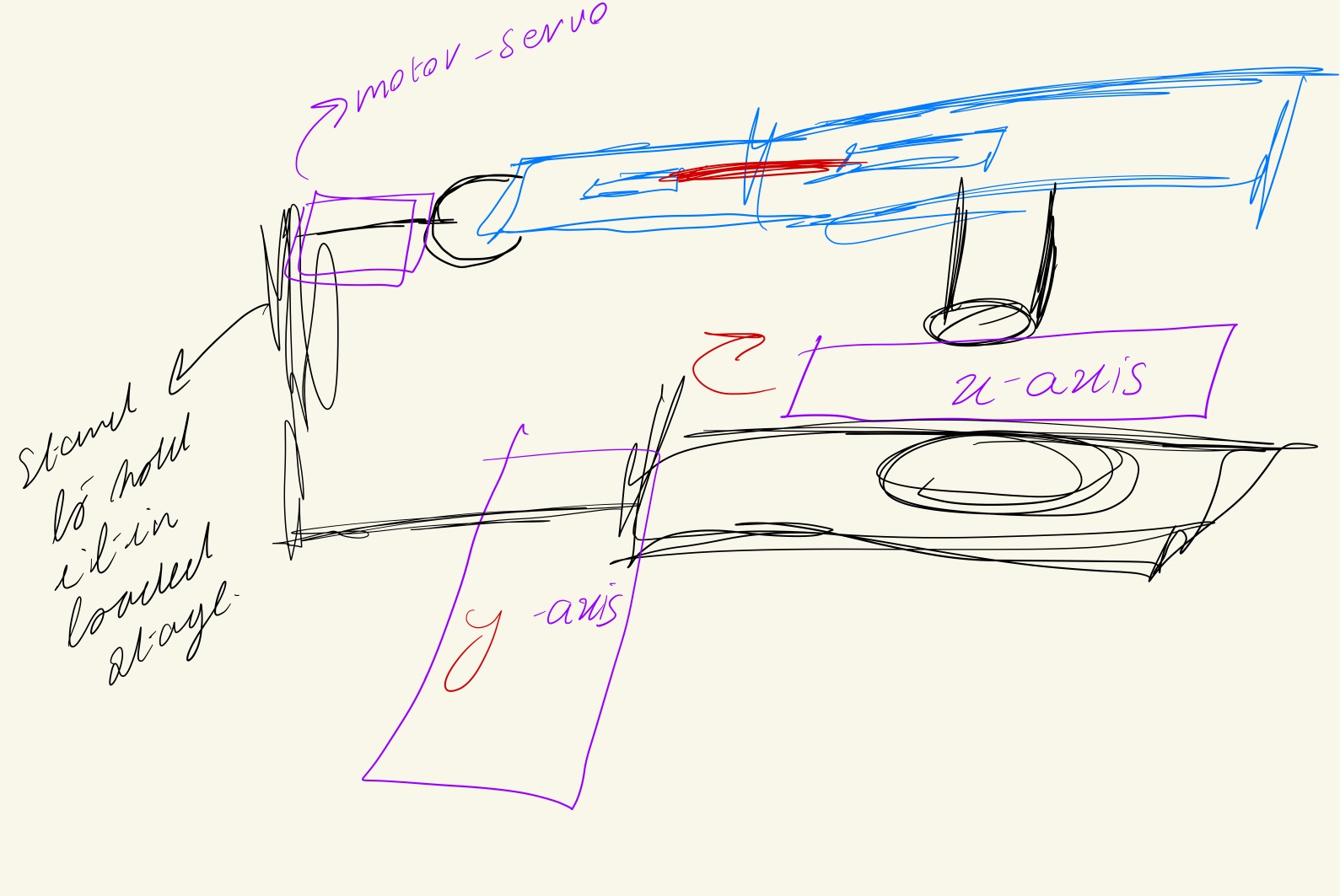
The side view demonstrates the use of two motors, one oriented for x-axis movement and the other one for y-axis movement.

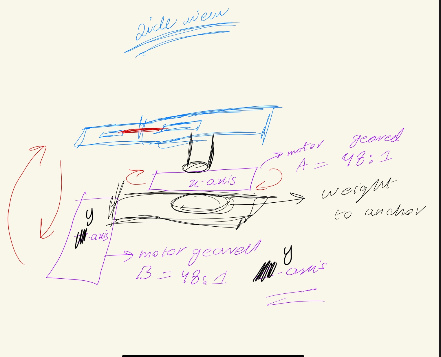
The supported stand on the left end with a claw-like  grappler helps keep the canon loaded. Upon trigger, it will release and let the tension of the elastic loose which will lead to forward release mechanism.

Arduino and P5 Program :

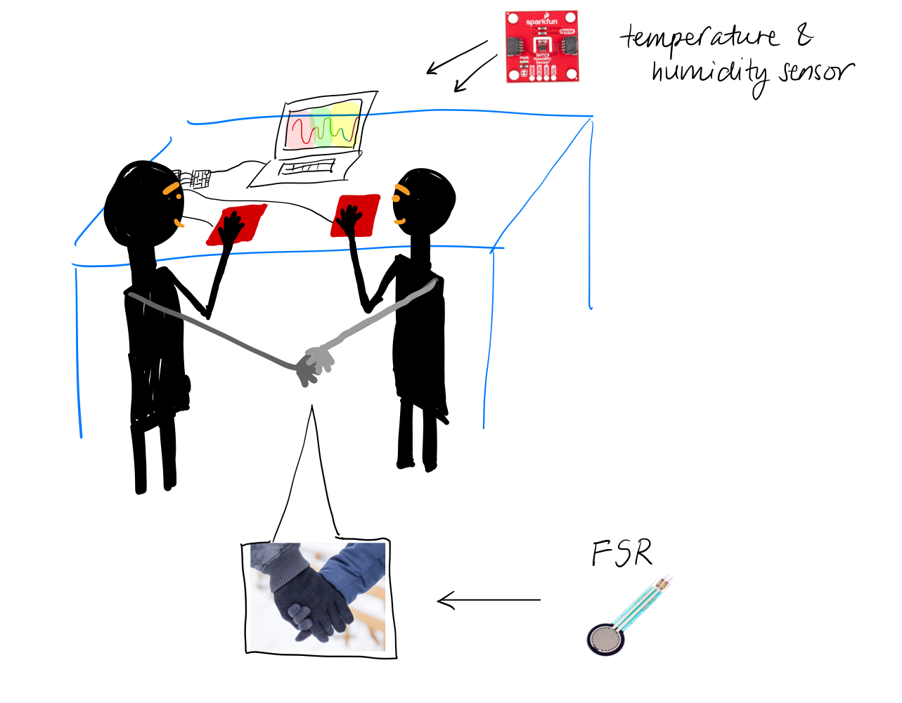
The movement of this canon will be controlled by gyroscope mounted on to gym-gloves. The gloves will also have the flex sensors, so that with hand tilt and movement, corresponding movement along x and y-axis will take place. When the hands are clenched , it will result to the release mechanism being triggered. A pressure sensor will be put underneath the hole/target to detect if the ball/sack has landed. The p5 program will first start off with a menu with  screen offering the user to play or go over instructions. This game will be both in virtual and real domain. The game will start with a 1 minute counter. For each corn in the hole, user will get response on the screen with animation and led will light up, while also points would increase.  When in reload state, the user won’t be able to move the robot, this is for convenience as to prevent user from mistakenly moving the robot while reloading. Once the game ends, the robot stops moving and the highscore displayed.

The arduino will control the movement of the three motors as an output signal (PWM), with last one being a servo, it will take input from the gyroscope and flex sensor for the controls. The Pressure sensor under the cornhole will trigger point system and this will be conveyed to the P5  program by and  after having read by the Arduino. The state of servo motor will be conveyed to the p5 program as well. In return, the p5 will communicate back the permission or the kill-switch condition to start or stop the program. It will process and display the state (i.e launch or reload), and will show the points alongside the timmer. I will add in safety nets too to prevent the machine from turning too much and breaking the structure/casing. Last but not the least, it will shutdown the connection between the gloves and the motors once the game has concluded.

Week 11 – Reading Response

Week 11 – Reading Response

Design Meets Disability:

The reading discusses how simple, thoughtful design can be both functional and beautiful, even for products aimed at disability or accessibility. The Eames splint, which was originally designed for injured soldiers, is appreciated for its aesthetic and innovative qualities. It challenges the idea that medical products should prioritize function over form. Additionally, it critiques how overly complex designs  intended to be universally accessible, often end up being cognitively inaccessible, highlighting the importance of simplicity.

The text differentiates the idea of “universal design” with the idea of “good design,” claiming that accessibility usually comes from simplicity rather than complexity. It references greate designers like the Eameses and Naoto Fukasawa for creating objects where form and function are seamlessly integrated without overcomplicating the user experience. Overall, the author highlights that designing for disability should not lower design standards but rather inspire innovation and beauty. After reading the text, I began rethinking how design for disability is often approached today. 

Final project concept – Drawing AI App

For my final project, I am developing a Python-based desktop application titled Drawing AI App, which merges interactive drawing, artificial intelligence recognition, and conversational voice feedback into a cohesive user experience. The project demonstrates how creative coding and AI integration can work together to create engaging, accessible tools for users of all skill levels.

Project Overview

Drawing AI App offers users a responsive digital canvas where they can sketch freely using a variety of drawing tools. Once a drawing is complete, an AI assistant attempts to recognize the object or shape, providing spoken and visual feedback. The application aims to create an experience that feels intuitive, light-hearted, and educational, balancing technical sophistication with user-centered design.

Core Features

Drawing Canvas
The application features a PyQt5-based drawing canvas with support for adjustable pen sizes, a color palette, eraser functionality, and a clear canvas button. The interface is designed for responsiveness and ease of use, providing users with a clean, modern environment for creative expression.

AI Drawing Recognition
Using OpenAI’s Vision API, the AI assistant analyzes the user’s drawings and offers recognition guesses, displaying confidence percentages for the top three predictions. If the AI’s confidence is low, it will prompt the user for additional clarification.

Voice Communication
The AI assistant communicates through text-to-speech functionality, initially implemented with pyttsx3 for offline use, with future plans to integrate OpenAI’s TTS API for more natural speech output. Voice feedback enhances interactivity, making the experience more immersive.

Educational Component
An integrated information section explains how AI recognition operates, encouraging users to engage with the underlying technology. Users can correct the AI’s guesses, offering a learning opportunity and highlighting the limitations and strengths of machine learning models.

Week 12: Final Project Progress

Finalized concept

For my final project, I have decided to create an interactive art piece that is based around the idea of friendship and human bonding. The piece requires there to be 2 users at a time, ideally friends. The idea of the art piece is to allow the users to watch their connection to each other visualized on the screen, based on their body temperatures and the way they are holding their hands.


As can be seen in the terrible sketch, the users will be asked to put on a glove on one hand each and hold hands. Inside one of the gloves, there will be a force sensitive resistor (FSR) attached. They will be then be asked to put their other free hand on the temperature sensor on the table.

In p5.js, each user generates their own plant-like/branch-like structure using Perlin noise loops, growing from opposite sides of the screen. The color of each plant reflects the user’s temperature reading, mapped to a color gradient. As the plants grow toward each other, their speed is controlled by how tightly the users are holding hands, measured by the FSR sensor. When their grip becomes strong enough, the plants meet and fuse in the center. Upon connecting, the colors blend into a new gradient based on the users’ combined temperature and the Arduino buzzer will be triggered to play a melody.

Arduino <–> p5.js communication

  • Arduino -> p5
    • FSR – send reading to p5
    • temperature sensor – send reading to p5
  • p5
    • map FSR and temperature readings to appropriate values to use for controlling speed and color
    • the magnitude of FSR reading changes the speed at which the 2 illustrations “grow” towards each other and connect
    • temperature sensor reading controls the color of the sketch
  • p5 -> Arduino
    • when the 2 illustrations touch and merge in the middle, p5 sends to Arduino a digital signal that starts a melody on the buzzer

Progress

I started creating the p5js interface and added basic interactions like showing the instructions, starting the illustration and going back to the homepage to restart.

I tried testing 2 of the temperature & humidity sensor from the IM equipment center but both didn’t work (most likely due to hardware breakages), so for the time being, I plan to stick to using the temperature sensor provided in our Sparkfun kit.

Week 11 – Introduce Final Project

Week 11 – Introduce Final Project

For my final project, I want to create an interactive olive tree installation that combines Arduino sensing with storytelling in p5.js. The tree will rely on both motion sensing and touch sensing to engage users with visual and auditory responses. On Arduino, I will use a motion sensor, where the tree detects when a person approaches. When someone is nearby, parts of the tree, like the trunk or leaves, will light up using LEDs.

Each olive on the tree will have a touch sensor, when the user touches an olive, it will light up an LED and display a story, memory, or message through p5.js, either as text, visuals, or audio. In addition, I was thinking of including a special designated olive that allows the user to record their own short stories or messages. These recorded interactions will be stored and replayed for future visitors, so that it creates an archive of shared experiences connected to the tree.

Week 11 – Serial Communication

Week 11 – Serial Communication

Task 1:

Prompt: Make something that uses only one sensor on Arduino and makes the ellipse in p5 move on the horizontal axis, in the middle of the screen, and nothing on Arduino is controlled by p5.

Code P5:

let circleX;
function setup() {
    createCanvas(600, 600);
    noFill();
}
function draw() {
     background("rgb(248,238,249)");
  stroke("purple");
 ellipse(map(circleX, 0, 1023, 0, width), height / 2, 100, 100);
   
     if (!serialActive) {
    background("#CE41E6");
    stroke("#white");
    textSize(50);
    text("Press Space Bar to select Serial Port", 20, 30, width - 30, 200);
  }
}
function keyPressed() {
    if (key == " ")
        setUpSerial();
}
function readSerial(data) {
    if (data != null) //
        circleX = int(data);
}

Arduino Code:

int lightPin = A0;  
void setup() {
  Serial.begin(9600);       
  pinMode(lightPin, INPUT);  
}
void loop() {
  int sensorValue = analogRead(lightPin);  
  Serial.println(sensorValue);            
  delay(5);                             
}

Task 2:

Prompt: Make something that controls the LED brightness from p5

For this project, I decided to imitate the sun: as the mouse moves from left to right across the screen, the brightness level on the screen and the connected LED both increase.

Code P5:

let ledBrightness = 0;
function setup() {
  createCanvas(600, 400);
  textSize(20);
}
function draw() {
  background(240);
  if (!serialActive) {
    fill(0);
    text("Press SPACE to select serial port", 20, 30);
  } else {
    // Display mapped brightness
    fill(0);
    text("LED Brightness: " + ledBrightness, 20, 30);
    fill(255, 150, 0);
    ellipse(mouseX, height / 2, map(ledBrightness, 0, 255, 10, 100));
  }
  // Update brightness based on mouseX
  ledBrightness = int(map(constrain(mouseX, 0, width), 0, width, 0, 255));
  // Send brightness to Arduino
  if (serialActive) {
    writeSerial(ledBrightness + "\n");
  }
}
function keyPressed() {
  if (key == ' ') {
    setUpSerial(); 
  }
}

Arduino Code:

int ledPin = 9; 
void setup() {
  Serial.begin(9600);
  pinMode(ledPin, OUTPUT);
  while (Serial.available() <= 0) {
    delay(300);
  }
}
void loop() {
  while (Serial.available()) {
    int brightness = Serial.parseInt();
    if (Serial.read() == '\n') {
      brightness = constrain(brightness, 0, 255);
      analogWrite(ledPin, brightness);
    }
  }
}
Task 3:

Prompt: take the gravity wind example (https://editor.p5js.org/aaronsherwood/sketches/I7iQrNCul) and make it so every time the ball bounces one led lights up and then turns off, and you can control the wind from one analog sensor. 

I connected Arduino to p5.js so the potentiometer controls the wind of the bouncing ball, and whenever the ball hits the ground, the LED blinks. Everything talks to each other through serial communication.

Link to task 3 video 

Code P5:

let velocity;
let gravity;
let position;
let acceleration;
let wind;
let drag = 0.99;
let mass = 50;
let serial;
let connectBtn;
let ledTriggered = false;
function setup() {
  createCanvas(640, 360);
  noFill();
  position = createVector(width / 2, 0);
  velocity = createVector(0, 0);
  acceleration = createVector(0, 0);
  gravity = createVector(0, 0.5 * mass);
  wind = createVector(0, 0);
  // setup serial connection
  serial = createSerial();
  let previous = usedSerialPorts();
  if (previous.length > 0) {
    serial.open(previous[0], 9600);
  }
  connectBtn = createButton("Connect to Arduino");
  connectBtn.position(10, height + 10); // button position
  connectBtn.mousePressed(() => serial.open(9600));
}
function draw() {
  background(255);
  // check if we received any data
  let sensorData = serial.readUntil("\n");
  if (sensorData.length > 0) {
  // convert string to an integer after trimming spaces or newline
    let analogVal = int(sensorData.trim());
    let windForce = map(analogVal, 0, 1023, -1, 1);
    wind.x = windForce; // horizontal wind force
  }
  applyForce(wind);
  applyForce(gravity);
  velocity.add(acceleration);
  velocity.mult(drag);
  position.add(velocity);
  acceleration.mult(0);
  ellipse(position.x, position.y, mass, mass);
  if (position.y > height - mass / 2) {
    velocity.y *= -0.9; // A little dampening when hitting the bottom
    position.y = height - mass / 2;
    if (!ledTriggered) {
      serial.write("1\n");   // trigger arduino LED
      ledTriggered = true;
    }
  } else {
    ledTriggered = false;
  }
}
function applyForce(force) {
  // Newton's 2nd law: F = M * A
  // or A = F / M
  let f = p5.Vector.div(force, mass);
  acceleration.add(f);
}
function keyPressed() {
  if (key === ' ') {
    mass = random(15, 80);
    position.y = -mass;
    velocity.mult(0);
  }
}

Arduino Code:

int ledPin = 9;
void setup() {
  Serial.begin(9600);
  pinMode(ledPin, OUTPUT);
}
void loop() {
  // send sensor value to p5.js
  int sensor = analogRead(A0);
  Serial.println(sensor);
  delay(100);
  // check for '1' from p5 to trigger LED
  if (Serial.available()) {
    char c = Serial.read();
    if (c == '1') {
      digitalWrite(ledPin, HIGH);
      delay(100);
      digitalWrite(ledPin, LOW);
    }
  }
}

Week 11 Project Exercises


Exercise 1.1

let port;
let connectBtn;
let baudrate = 9600;
let lastMessage = "";

function setup() {
  createCanvas(400, 400);
  background(220);

  port = createSerial();

  // in setup, we can open ports we have used previously
  // without user interaction

  let usedPorts = usedSerialPorts();
  if (usedPorts.length > 0) {
    port.open(usedPorts[0], baudrate);
  }

  // any other ports can be opened via a dialog after
  // user interaction (see connectBtnClick below)

  connectBtn = createButton("Connect to Arduino");
  connectBtn.position(80, 200);
  connectBtn.mousePressed(connectBtnClick);

}

function draw() {
  background("255");


  // Read from the serial port. This non-blocking function
  // returns the complete line until the character or ""
  let str = port.readUntil("\n");
  if (str.length > 0) {
    // Complete line received
    // console.log(str);
    lastMessage = str;
    
  
  }


  // Display the most recent message
  text("Last message: " + lastMessage, 10, height - 20);

  // change button label based on connection status
  if (!port.opened()) {
    connectBtn.html("Connect to Arduino");
  } else {
    connectBtn.html("Disconnect");
  }
  
  
  ellipse(lastMessage,10,20,20)
}

function connectBtnClick() {
  if (!port.opened()) {
    port.open("Arduino", baudrate);
  } else {
    port.close();
  }
}


Exercise 1.2

let port;
let connectBtn;
let baudrate = 9600;
function setup() {
  createCanvas(255, 285);
  port = createSerial();
  let usedPorts = usedSerialPorts();
  if (usedPorts.length > 0) {
  port.open(usedPorts[0], baudrate);
 } else {
  connectBtn = createButton("Connect to Serial");
  connectBtn.mousePressed(() => port.open(baudrate));
 }
}
function draw() {
  background(225);
  circle(140,mouseY,25,25):
  let sendtoArduino = String(mouseY) + "\n"
  port.write(sendtoArduino);
}

Exercise 1.3


int led = 5;
void setup() {
  Serial.begin(9600);
}
 
void loop() {
  if (Serial.available()) {
    int ballState = Serial.parseInt(); 
    if (ballState == 1) {
      digitalWrite(led, HIGH); // ball on ground
    } else {
      digitalWrite(led, LOW); // ball in air or default
     }
  }
  // read the input pin:
  int potentiometer = analogRead(A1);                  
  int mappedPotValue = map(potentiometer, 0, 1023, 0, 900); 
  // print the value to the serial port.
  Serial.println(mappedPotValue);                                            
  
  delay(100);
}


Preliminary Concept for Final Project

For my Intro to IM Final Project, I wanted to do something that helps me feel so “free” in the sense of creativity: visual arts, together with something I get so excited to experience: music. I’d like to weave both visual arts and music into an interactive art gallery with rooms containing a visual scene with background music. Unlike a traditional art gallery, this art gallery comes with an “escape room” challenge: each art room is a phase of an “escape room” challenge for which users must interact with through musical jamming to reach the next phase (or proceed to the next art room). Once all phases are passed, the user successfully completes the escape room challenge! In this way, users should interact with every artwork in the art gallery if they are to pass this “escape room” challenge.

User decisions can be enabled by analog/digital sensors. For example, users can control an avatar using joysticks to move up, right, left, or down within the escape room setting (eg. a big treehouse). The user should use clues involving the visual artwork and the musical sounds heard from p5js to figure out a solution that involves jamming in a corrected/accepted way to pass the phase and reach the next phase. The jamming could be through a “piano” made with force sensitive resistors (FSR), each connected to a buzzer. The connection of each FSR to a buzzer is crucial as it enables multiple musical notes to be heard at the same time.

The above is the minimum viable product. I was also inspired by the generative text data project from week 4 which involves creating a poem from a corpus of words. If time allows, an additional feature could be incorporated: after the escape room challenge is completed, the user can try to create poem artwork by jamming. Based on the user’s choices, each word of the poem on an artwork are selected and displayed.

Week 11 – Serial Communication

1. Concept

There are 3 parts to the project:

(1) Light Dependent Resistor (LDR) readings are sent from Arduino to p5js. The ellipse in p5js moves on the horizontal axis in the middle of the screen depending on the LDR readings. Nothing on arduino is controlled by p5js.
(2) Control the LED brightness from p5js using mouseX position. The more right the mouse position, the higher the LED brightness.
(3) Taking the gravity wind example (https://editor.p5js.org/aaronsherwood/sketches/I7iQrNCul), every time the ball bounces one led lights up and then turns off, and you can control the wind from the potentiometer (analog sensor).

2. Highlights: Challenges and Overcoming Them

(1) The circle position was not changing in response to the brightness of the surroundings. We attempted to tackle this problem by checking the serial monitor as to whether LDR readings are being read. After confirming the LDR’s functionality, we closed the serial monitor proceeded to use p5js and use the right serial port. However, the circle position was still not changing. With help from Professor, we streamlined our code to include just about all that seemed necessary. This worked!


(2) The LED was flickering. We did not know why. Alisa thought that the delay(50) must be at after instead of before analogWrite(ledPin, brightness). However, that did not solve the problem. Samuel thought to remove the delay(50). It still did not work. We decided to try to map the mouseX position (ranging from 0 to 600) to the range of 0 to 255 in Arduino instead of p5js. This worked!


(3) To code the 3rd assignment. I worked alongside many different individuals, Alisa, Samuel, Haris, (even Prof Aya’s slides). I was having trouble at every stage of the hardware aspect, from safari stopping the code from interacting with the Arduino, to then having serial issues with the laptop. I was able to piece together work until I finally had it working in the end. The coding aspect was simple overall, as the base code only had to be minority amended to take inputs from the Arduino, and the LED had to complete an action based on the running programme.

3. Video

Part 1:

Part 2:

Part 3:

4. Reflection and Future Areas of Improvement

Our challenges emphasized the need for understanding the code that allows communication between p5js and Arduino. Without understanding the code, it is difficult to make the right removals or changes necessary to achieve the results we are hoping to.

It would be great to find out why the LED did not flicker when the mapping was performed in Arduino rather than p5js. Is this related to PWM?

Week 11 — Final Project Brainstorming

So for my final project, I initially brainstormed with a classmate to possibly incorporate something that has to do with the arduino wifi board, a sort of multi-player, but tactile game, like Among us. However, I sort of branched out a bit after thinking about it a bit more.

So, I’m planning to build something a little… revealing. Inspired by those classic lie detector tests you see in movies (minus the intense interrogation lol), I want to create a physical system that reacts to some basic physiological signs – specifically, changes in skin conductivity and heart rate.

The core idea is to use copper tape on a surface connecting a circuit when a user’s two fingers touch. When a person places their fingers on the tape, they’ll complete a circuit. Now, the “lie detector” part comes in because, supposedly, when people are stressed or nervous (like when they’re lying!), their palms tend to get a little sweatier. This increased moisture actually makes their skin more conductive, which the arduino can sense as a change in the electrical signal going through the copper tape. I’m not too sure how accurate this might be so I’ll have to test it on a prototype before building it properly.

In addition to that, I want to incorporate a pulse sensor (as recommended by my classmate Ali) to get a reading on the user’s heart rate. This is another classic indicator that can fluctuate under stress.

In terms of the p5, I envision a game or visualization on the screen that reacts to these physiological inputs. The p5 sketch will be listening for data from the arduino about skin conductivity (how “connected” you are to the copper tape) and your pulse. The game aspect is still a bit in development, but I’m thinking of something where your “truthfulness” (based on the sensor readings) influences the outcome. Maybe there’s a visual element that changes based on how conductive your skin is, or a character that reacts to your heart rate. I’m thinking a cheesy romance game or one of those truth or dare type scenarios. I’m not too sure yet. I’m planning to build a prototype to test the sensor readings this weekend.

My goal is to make the interaction engaging and the responses clear and timely. I want the person interacting with it to feel like the system is really “listening” to them, even if it’s just through these simple sensor inputs. Looking forward to diving deeper into this and seeing how it evolves.