Readings

Reading 1

Reading Tom Igoe’s blog post on the “greatest hits (and misses)” of physical computing really made me reflect on how approachable and endlessly creative this field can be. As someone who’s still growing my understanding of interactive technology, I found his message super reassuring, especially the idea that it’s okay to revisit classic project ideas like light-sensitive instruments or pressure-sensitive floors. Instead of feeling like I’m copying someone else’s work, Igoe made me realize that there’s value in reinterpreting those familiar ideas in new, personal ways. It reminded me that creativity isn’t always about inventing something completely new—it’s also about seeing old ideas through a different lens.

Igoe’s emphasis on how machines don’t understand intention—only action- was what caught my attention the most. It got me thinking about how important it is to really consider how people will interact with what I make. It’s not just about the cool factor of the tech; it’s about how people feel when they use it. Igoe’s point about designing systems that are intuitive and human-centered stuck with me. It encouraged me to start paying more attention to how people move, gesture, and react in everyday life—because that’s where meaningful interaction begins.

Reading 2

In “Making Interactive Art: Set the Stage, Then Shut Up and Listen,” Tom Igoe presents a thoughtful perspective on the role of the artist in interactive work. He emphasizes that the artist’s job is to create an environment that invites engagement, not to dictate how people should respond. This idea stood out because it shifts the focus from controlling the audience’s experience to trusting them to find their own way through the piece. Igoe’s comparison to theater directing, where the director sets the scene but lets the actors interpret it, captures this idea well. It reminded me that successful interaction often comes from subtle suggestions, not detailed instructions.

What I found especially valuable was Igoe’s insistence on listening, observing how people interact with a piece instead of trying to steer them. It’s a reminder that interactive art is a two-way conversation, and part of the creative process is stepping back and allowing space for surprise and interpretation. This approach encourages more open-ended, personal experiences for the audience.

Week 9 – Analogue and Digital

Concept

Link:  https://drive.google.com/file/d/1iGY1zePkL1vzLj20TXHqm8l7hkp8WpBZ/view?usp=sharing

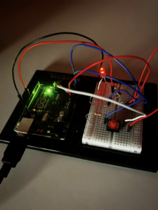
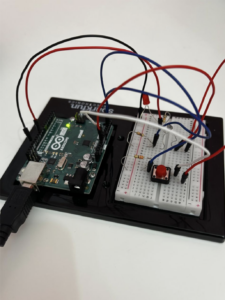
For this assignment, I made a circuit that mimics the performance of solar-powered garden lights. The LED automatically turns on when the environment is dark and off when the environment is bright. I used a photoresistor  to sense the light around the environment and included a button for manual control, controlling the LED when the environment is dark. The LED automatically turns on when the light is low. If the button is pressed during darkness, the LED turns off but with a brief delay before turning on again. When there is enough ambient light, the LED turns off automatically.

Code Highlight (Arduino Code)

const int LED_PIN = 9;             // LED that turns on in dark, or with button
const int LIGHT_SENSOR_PIN = A2;   // Light sensor (photoresistor)
const int BUTTON_PIN = A3;         // Button input (wired to GND)


const int LIGHT_THRESHOLD = 600;   // Adjust based on your light conditions


void setup() {
  pinMode(LED_PIN, OUTPUT);
  pinMode(BUTTON_PIN, INPUT_PULLUP); // Use internal pull-up resistor
  Serial.begin(9600); // Optional: monitor values for debugging
}


void loop() {
  int light_value = analogRead(LIGHT_SENSOR_PIN);
  int button_state = digitalRead(BUTTON_PIN);


  Serial.print("Light: ");
  Serial.print(light_value);
  Serial.print(" | Button: ");
  Serial.println(button_state);


  if (light_value < LIGHT_THRESHOLD) {
    // DARK: turn LED ON automatically
    digitalWrite(LED_PIN, HIGH);
  } else {
    // BRIGHT: turn LED ON only if button is PRESSED (LOW)
    if (button_state == LOW) {
      digitalWrite(LED_PIN, HIGH);
    } else {
      digitalWrite(LED_PIN, LOW);
    }
  }


  delay(100); // Short delay to reduce flicker and serial flooding
}

The code reads the amount of light from a sensor and controls an LED based on that. When it’s dark, the LED turns on automatically. When it’s bright, the LED turns off, but if the button is pressed, the LED will turn on even in the light. The button works like a manual override. There’s a small delay in the code to avoid flickering, and the system checks the light level regularly to adjust the LED accordingly.


Challenges

I faced several issues while working on this project. First, it was confusing to make the photoresistor function properly, especially to understand how to make the LED respond to light and darkness. I also struggled to set the correct light threshold so that the LED would turn on at the right time. Plugging in the photoresistor correctly was challenging, and I had to figure out how to use a voltage divider. When I added the button, it didn’t work at first because I didn’t know how to connect it through the internal pull-up resistor. I also had trouble coding to make the LED turn on automatically when it’s dark and just the button when light. It was a lot of trial and error to make everything work the way I desired.


Week 9 Reading

Physical Computing’s Greatest Hits(and misses):

I am particularly interested in theremin-like instruments, gloves, and video mirrors. I believe that these three examples of physical compute (in harmony and implemented altogether) have the potential to change the representation of the lived physical world. To extend these concepts, I thought of methods of taking input from the environment. These could be the sounds of birds, wind, the temperature, the perceived luminosity of the sun (at the place of input), as well as small movements (either from the wind or sound). Combining these inputs together and processing them, an algorithm can generate certain sounds. This music then comes together with video mirroring and processing, where the composed music dictates a new perception of the scenery / place of physical compute. I found value in the limitations explained in this reading, as the meaning attributed to the actions performed by physical compute and the method of input is key towards making a truly interactive and valuable physical compute experience. To address those, if I were to use the previous example I would think of a way (through testing) by seeing how people received the experience, and how to fine tune it. Things within this line are intuitive experience (ease of use), meaning from interaction, and ability to interact for a sufficient amount of time whilst maintaining meaningful interaction.


Making Interactive Art: Set the Stage, Then Shut Up and Listen.


This reading builds on ‘Physical Computing’s Greatest Hits (and misses)’ by explaining the intricacies of limitations in the design of interactive art. The concept of intuition in interaction is therefore represented as the ability of a person to understand and find meaning in the interaction with the artwork. I found the organization and flow of this reading very helpful because it helped re-iterate and solidify the concepts of listening (by both the artist and the audience) and the statement made by the artist. The statement (as I understand it) is not a standalone expression, but rather an interactive conversation, that aims to have a meaningful exchange of actions and expressions by both the artist and his/her art and the audience.

Week 9 Sensor


For this project, I decided to use a photoresistor to create a light that detects a light source nearby.

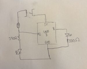
To implement this, I used two circuits; one connected to 5V power supply and another connected to the analog pins, whose power level could be controlled by the analogWrite on IDE. The circuit was not too complicated, connect a manual toggle switch to one side of the circuit, leading into a photoresistor connected to pin A2, leading into the first LED. This would mean the first LED would only light up if  the switch was toggled on. This meant that we could see an indicator if the device is working. Next, connected to pin 8 the other LED was connected. This meant that we can control this LED digitally with the arduino. In the circuit, we could use the input we got from A2 to determine if power should be sent to pin 8.

IMG_8238

int analogPin = A2;
int lightSensor;
int brightness;
void setup() {
  // put your setup code here, to run once:
pinMode(8, OUTPUT);
pinMode(A2, INPUT);
brightness = 128;

}

void loop() {
  // put your main code here, to run repeatedly:
lightSensor = analogRead(analogPin);
if(lightSensor > 500){
analogWrite(8, 1000);
} else {
analogWrite(8, 0);
}
}

The challenges were that it took a long time to make sure the code and the circuit were both correct. One being correct while the other being wrong would mean the whole thing would not work. Hence, in my making process, I took time testing the two parts individually. Initally there was some confusion on my end pertaining to the difference between analog and digital writing, as using the wrong one meant my LEDs were not lighting up.

This project could definitely be made more complex. I think adding a variety of lights and changing the different thresholds to which each individual LED would light up is a good way to make this project more useful.

Week 9 Analogue + Digital

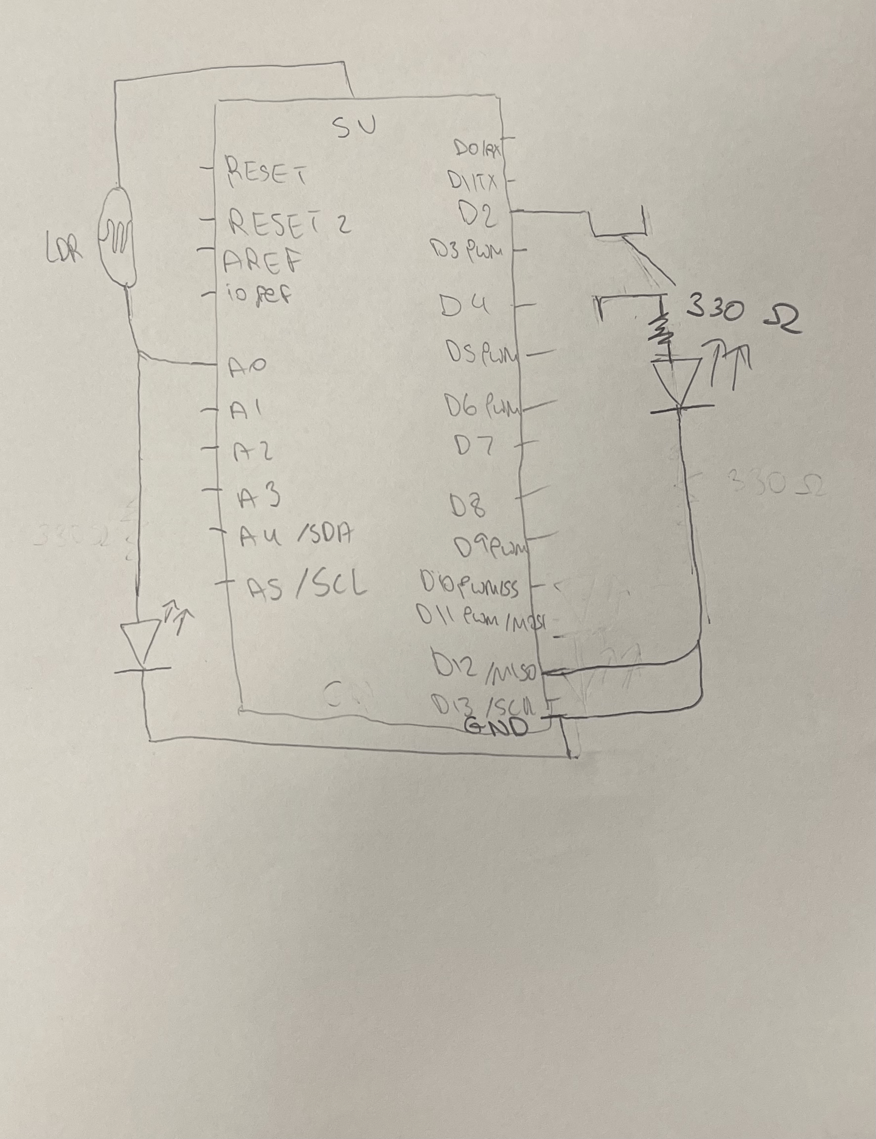
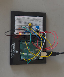
For this assignment I started by connecting one push-switch to one LED, and I used that as the basis of my draft schematic and work. I then re-drew my schematic and included the photoresistor (LDR) sensor. Here I faced challenges in both the hardware and software, specifically within the timing of the code. Initially, the light would stay on for too long, and I rechecked the timing of my Arduino code and adjusted it to be in a shorter high (on) state.


const int ldrPin = A2;              // LDR connected to analog pin A0
const int buttonPin = 2;            // Push button connected to digital pin 2
const int ledAnalogPin = 10;         // PWM LED pin
const int ledDigitalPin = 11;       // On/off LED pin

void setup() {
  pinMode(buttonPin, INPUT);
  pinMode(ledAnalogPin, OUTPUT);
  pinMode(ledDigitalPin, OUTPUT);
  Serial.begin(9600);
}

void loop() {
  int ldrValue = analogRead(ldrPin);        
  int brightness = map(ldrValue, 0, 1023, 255, 0);  // This adjusts the brightness

  analogWrite(ledAnalogPin, brightness);

  int buttonState = digitalRead(buttonPin);

  if (buttonState == HIGH) {
    digitalWrite(ledDigitalPin, HIGH);
  } else {
    digitalWrite(ledDigitalPin, LOW);
  }

  delay(100);
}

For the schematic I followed the fritz schematics format:


Video Demonstration:

https://drive.google.com/file/d/1kAYD6v6C86fbftmEfKM37j6jtumxzql1/view?usp=sharing


Some challenges I would still like to overcome and solve better are the output of the LED from the photoresistor (LDR) sensor, as I wanted the output to be stronger. I will address these issues by having a closer adherence to the schematic and a better methodology of implementing the changes to the circuit (thinking of what would happen if I added a certain connection or made a specific change before making that change).


Week 9 – Digital and analog sensors

For this week’s assignment, we were tasked with building a project that controls at least one LED using a digital sensor and another using an analog sensor. Inspired by the iconic flashing lights of police sirens, I created a setup where two LEDs alternate in a flashing pattern, mimicking the red and blue lights with a twist, you can control the flashing speed in real-time.

Video link :
https://drive.google.com/drive/folders/162WwnI-EoY3XR8ZpefkEw1aVkdSKWeLl?usp=drive_link

Components used :

– Arduino Uno
– Push Button (Digital Sensor)
– Potentiometer (Analog Sensor)
– Red LED
– Blue LED
– 2 330Ω Resistors
– Breadboard & Jumper Wires


How it Works:

The system is activated with a push button, which acts as the digital trigger. Once pressed, the LEDs begin their alternating flashing sequence, simulating the back-and-forth of police siren lights.

The potentiometer controls the speed of the siren lights. Its analog value is read and mapped using the map() function to determine the timing of the red LED’s fade cycle. The red LED smoothly fades in and out using analogWrite(), and the duration of this full cycle is used to time the LED transitions.

When the red LED finishes fading out, the blue LED turns on and remains lit for the same duration that the red LED is off. As soon as the red LED begins its next fade-in cycle, the blue LED turns off. This creates a continuous alternating pattern between red and blue LEDs, closely resembling the flashing of police lights.

One of the main challenges I faced was ensuring that the blue LED only turns on when the red LED is completely off. Initially, the timings between the LEDs were slightly off, which caused both LEDs to overlap or leave gaps between transitions.

Perfecting the fade timing and ensuring the blue LED’s on-time was synced precisely with the red LED’s off-time took some fine-tuning. I had to carefully balance the delays and the mapped potentiometer values to make the flashing appear smooth and consistent, without any flicker or overlap.

// Pin definitions
const int POT_PIN = A2;      // Potentiometer connected to A2
const int BUTTON_PIN = 2;    // Push button connected to D2
const int RED_LED_PIN = 9;   // Red LED connected to D9 
const int BLUE_LED_PIN = 10; // Blue LED connected to D10

// Variables
int potValue = 0;            
bool buttonState = false;    
bool lastButtonState = false; 
bool systemActive = false;   

// Red LED fading variables
unsigned long fadeStartTime = 0;
int fadeDuration = 2000;     // Default fade duration (in ms)
int currentBrightness = 0;   // Current red LED brightness
enum FadeState { FADE_IN, FADE_OUT, GAP, IDLE };
FadeState fadeState = IDLE;

void setup() {
  // Initialize pins
  pinMode(BUTTON_PIN, INPUT_PULLUP);
  pinMode(RED_LED_PIN, OUTPUT);
  pinMode(BLUE_LED_PIN, OUTPUT);
  
  // Start with all LEDs off
  digitalWrite(BLUE_LED_PIN, LOW);
  analogWrite(RED_LED_PIN, 0);
}

void loop() {
  // Read potentiometer and map to fade duration (100ms to 5000ms)
  potValue = analogRead(POT_PIN);
  fadeDuration = map(potValue, 0, 1023, 100, 5000);

  buttonState = digitalRead(BUTTON_PIN);
  
  if (buttonState == LOW && lastButtonState == HIGH) {
    // Toggle system on/off
    systemActive = !systemActive;
    
    if (systemActive) {
      // Start the cycle
      fadeState = FADE_IN;
      fadeStartTime = millis();
    } else {
      // Turn everything off
      fadeState = IDLE;
      digitalWrite(BLUE_LED_PIN, LOW);
      analogWrite(RED_LED_PIN, 0);
    }
    delay(50); // Debounce delay
  }
  lastButtonState = buttonState;

  // Only process fading if system is active
  if (systemActive) {
    unsigned long currentTime = millis();
    unsigned long elapsedTime = currentTime - fadeStartTime;
    
    switch (fadeState) {
      case FADE_IN:
        currentBrightness = map(elapsedTime, 0, fadeDuration, 0, 255);
        digitalWrite(BLUE_LED_PIN, LOW); // Blue off during fade
        
        if (elapsedTime >= fadeDuration) {
          fadeState = FADE_OUT;
          fadeStartTime = currentTime;
        }
        break;
        
      case FADE_OUT:
        currentBrightness = map(elapsedTime, 0, fadeDuration, 255, 0);
        digitalWrite(BLUE_LED_PIN, LOW); // Blue off during fade
        
        if (elapsedTime >= fadeDuration) {
          fadeState = GAP;
          fadeStartTime = currentTime;
          digitalWrite(BLUE_LED_PIN, HIGH); // Blue on during gap
        }
        break;
        
      case GAP:
        currentBrightness = 0;
        
        if (elapsedTime >= fadeDuration) {
          fadeState = FADE_IN;
          fadeStartTime = currentTime;
          digitalWrite(BLUE_LED_PIN, LOW); // Blue off when fade starts
        }
        break;
        
      case IDLE:
        // Do nothing
        break;
    }
    
    // Update red LED brightness
    analogWrite(RED_LED_PIN, currentBrightness);
  }
  
  delay(10);
}


In the end, it all helped me better understand PWM control, timing logic, and how to coordinate multiple components using both analog and digital inputs on the Arduino.

Week 9 – Reading Responses

Physical Computing’s Greatest hits and misses

This article provides an intriguing perspective on consistent themes and what are some aspects needed to understand what is physical computing. The conversation about theremin-like devices as popular starter projects, highlighted by their ease of use with photocells or distance sensors, is logical, just as the description of glove-related initiatives like Megatap 3000, which are captivating because of their link to daily tasks. From the reading, I noticed that there exists a favorable bias toward initiatives that promote significant physical involvement and creativity, illustrated by the criticism of “hand-waving” interfaces compared to the commendation for more organized interactions such as drum gloves. The reading didn’t explicitly alter my beliefs, but it offered a more defined structure for examining prevalent patterns and design issues in interactive systems.

Making Interactive Art: Set the Stage, Then Shut Up and Listen

Tom Igoe’s discussion on interactive art show that creators ought to “prepare the environment, then remain silent and observe.” His case against pre-planned audience interpretation echoes student reflections, with some applying his concepts by eliminating directions from their projects or realizing that interactive art promotes open discussions instead of presenting a singular perspective. The comparison to guiding actors—where proposing intentions is acceptable but imposing emotions restricts authenticity—really suggests the notion that the audience should have room for their own true reaction. The text made me consider how interactive art can be practiced, similar to a performance, to enhance audience involvement without excessive guidance.

Week 9 – Reading response

Physical Computing’s Greatest Hits (and misses)

The reading gives a nice overview of recurring themes in physical computing, from glove controllers and theremin-like instruments to meditation devices and LED-heavy projects. What stood out to me is how these categories reveal both the creativity and the comfort zones of makers in the field. Igoe doesn’t criticize repetition, but rather suggests that familiarity in concept doesn’t make it not innovative. It reminds us that an idea can still be original by putting our own twist on it, even if it has been done before.

Making Interactive Art: Set the Stage, Then Shut Up and Listen

The second reading emphasizes the importance of allowing interactive artworks to speak for themselves without over-explaining their meanings. It mentions how the artists often provide detailed interpretations alongside their interactive pieces, which can inadvertently dictate the audience’s experience and limit personal engagement. Igoe advocates for creating environments that invite participants to explore and derive their own interpretations, suggesting that the artist’s role is to set the context and then step back to observe how the audience interacts with the work. I somewhat agree with this, as I do believe the interactive art should speak for itself. But also I do think that some interactive artworks do need explanation, as having users “mess” with it however they like might break the design or change the important pre-set setting. I guess the design should make it obvious what is to be touched and what not, but I think sometimes people can interpret it wrong without proper instructions.

Assignment 9 – Reading Response 2 (Physical Computing’s Greatest Hits (and misses))

Reading this text made me realize that creativity in physical computing doesn’t always mean coming up with a brand new idea, it can be just as interesting to take something familiar and make it your own. Projects like theremin-style instruments or drum gloves keep showing up repeatedly, but each version reflects the person who built it. I used to worry that picking a common idea would make my work seem unoriginal, but now I see that it’s more about how you approach it. Even if something’s been done before, there’s always room to add your own twist or explore a new angle. That actually feels kind of helpful, knowing I don’t have to reinvent the wheel to make something meaningful.

What also stood out to me was how these projects go beyond just being technical, they’re about how people interact with them. Whether it’s something playful like a tilty table or something more emotional like a remote hug device, each project invited a different kind of connection. Even the ones that seemed purely visual, like video mirrors or waving grass, sparked curiosity. It made me think that physical computing is really about creating experiences, not just building stuff. That realisation was exciting, because it means there’s room for personality, emotion, and fun in the work I create.

Assignment 9 – Reading Response 1 (Making Interactive Art: Set the Stage, Then Shut Up and Listen)

Reading this peice made me pause and rethink how I approach interactivity. I’ve definitely been guilty of overexplaining my work, or failing to consider what an inexperienced user might try to do with, most notably in our midterm projects for this very course. It was easy to tell the audience of these projects exactly what they were supposed to do as opposed to watching them actually use it and naturally interact with it. But this reading reminds me that interactive art isn’t about controlling the outcome. It’s about inviting possibility. The idea that the artwork is just the beginning of a conversation really stuck with me. It shifts the focus away from self-expression and toward shared experience, which honestly feels more generous, and more exciting.

What stuck with me the most was the reminder to “listen”. To actually observe what people did, how they interacted, what they didn’t do, and keep that in mind for future projects. We can’t control how people will react to things, but we can control our reactions to them. Letting go of control isn’t easy, but it might be the most meaningful part of the process overall.