Week 9 – Traffic(Lights) Sounds

Concept

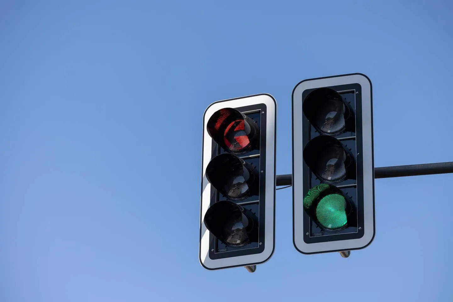
For my project, I developed a traffic light system that uses sound to provide directions. This solution addresses the challenge pedestrians face in reading traffic lights during the day, particularly when sunlight makes the signals hard to see. The system uses an LDR (Light Dependent Resistor) to detect light levels above a certain threshold, activating a buzzer that beeps twice for “go” (green) and once for “stop” (red). This feature helps pedestrians who may struggle to see the traffic lights in bright sunlight. At night, when the lights are easily visible, the buzzer remains off, reducing unnecessary noise.

Implementation

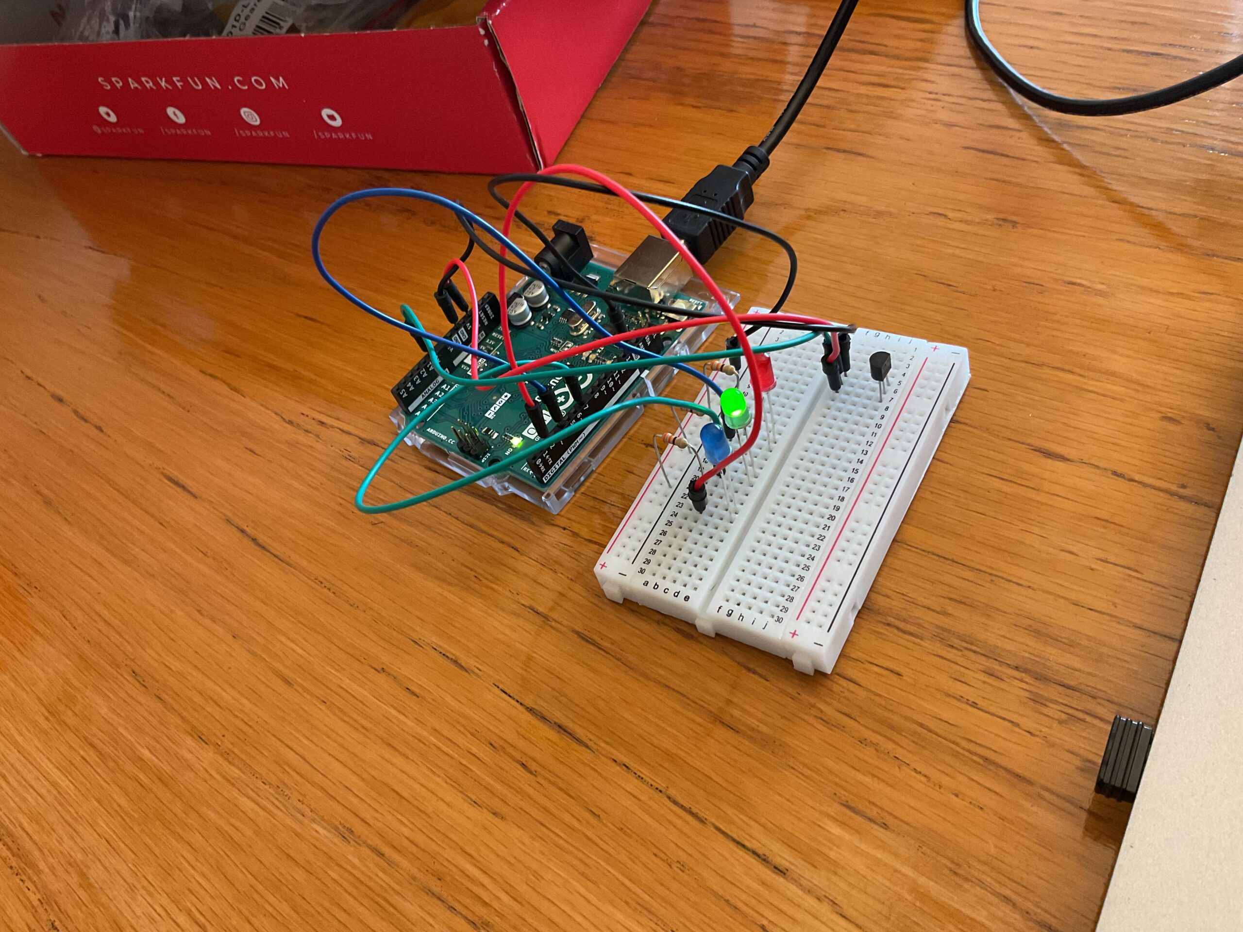
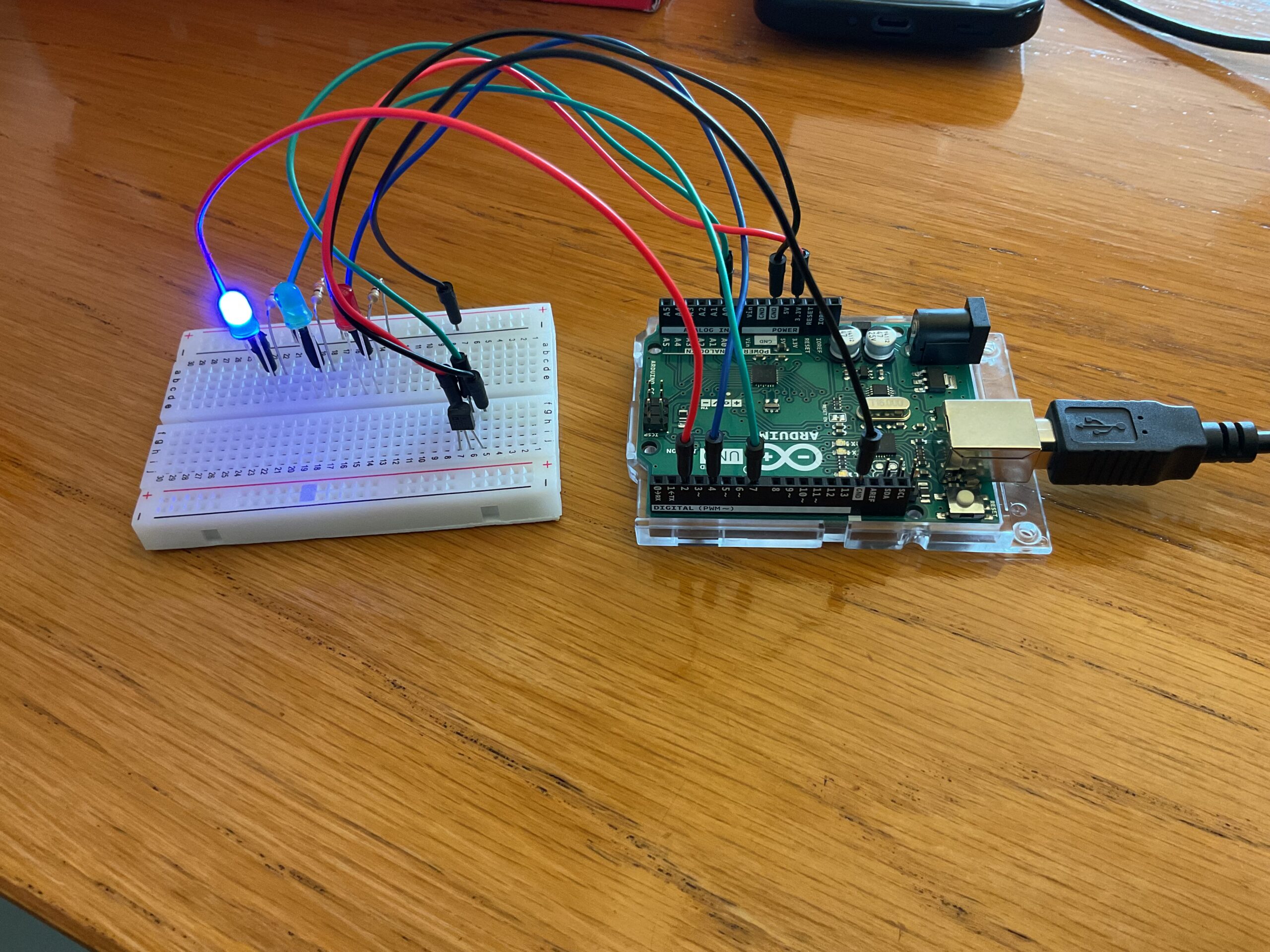
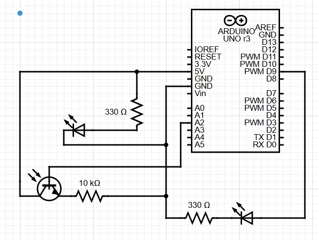
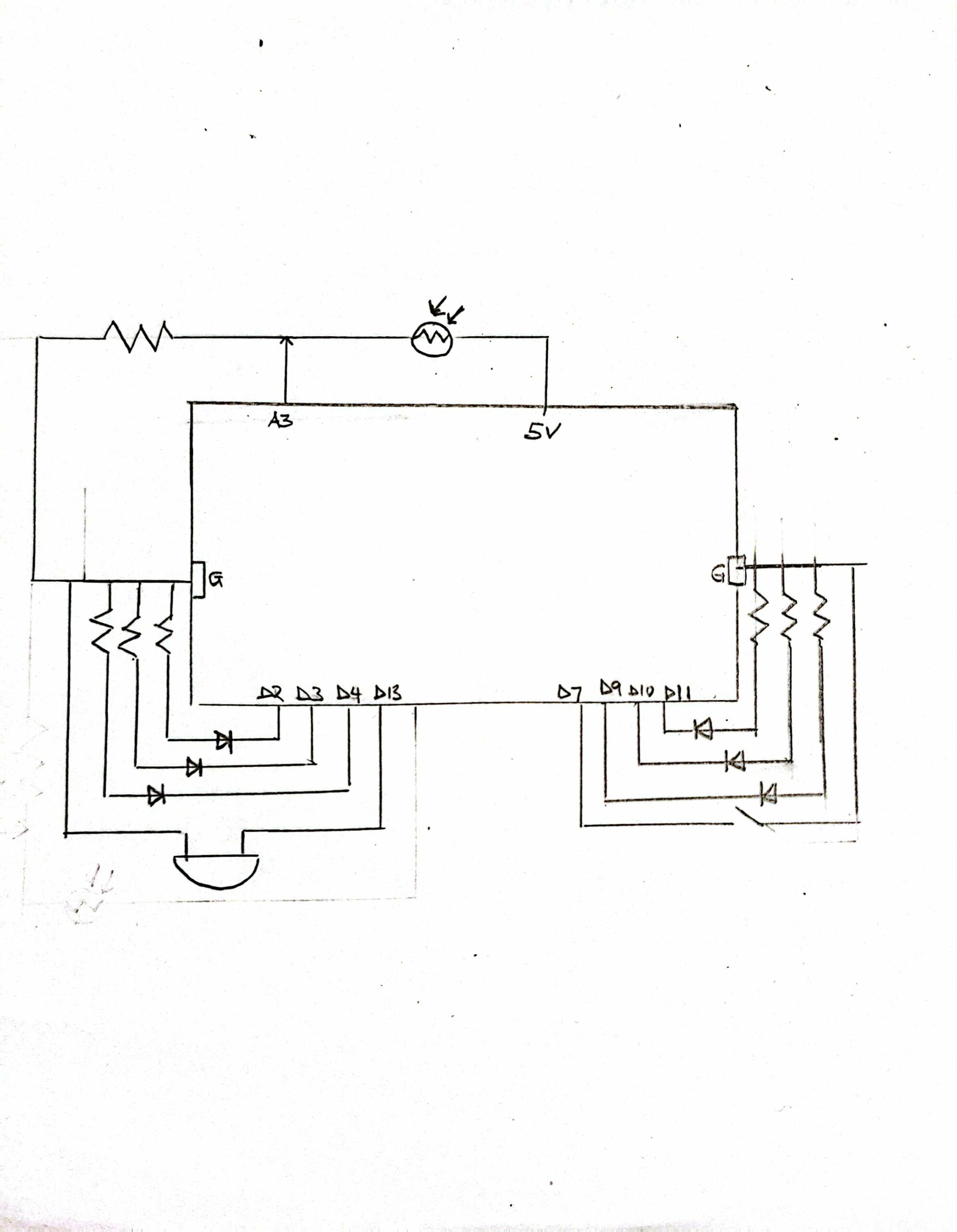
The project uses the following components: 6 LEDs, an LDR, a buzzer, resistors, wires, and a switch. The switch is particularly useful for stopping and resetting the system. The buzzer is triggered when specific LEDs are on, and the LDR reading exceeds a set threshold. The LEDs are divided into two groups: one for pedestrian signals and the other for vehicle signals. The buzzer sound is dependent on the pedestrian signal’s color: it beeps twice when the light is green and once when it is red.

Images and sketch

Code Highlights

I’m particularly proud of how I managed the buzzer’s beeping pattern using functions, classes, and conditional statements. Below are some key snippets of the code. 

void beepOnce(int note, int duration) {
  tone(buzzer, note, duration);   // Play the note on the buzzer
  delay(duration + 50);           // Wait for the note to finish
  noTone(buzzer);                 // Stop the sound
}

void beepTwice(int note, int duration) {
  tone(buzzer, note, duration);   // Play the note on the buzzer
  delay(duration + 50);           // Wait for the note to finish
  noTone(buzzer);                 // Stop the sound
  delay(100);                     // Short delay before second beep
  tone(buzzer, note, duration);   // Play the note again
  delay(duration + 50);           // Wait for the note to finish
  noTone(buzzer);                 // Stop the sound
 
ldr_value = analogRead(ldrpin); // Read the LDR sensor value
  if (ldr_value > 600) {  // Only beep if LDR value is greater than 600
    beepTwice(NOTE_E4, 300);  // Beep twice when Side 1 is Green
  }
 
ldr_value = analogRead(ldrpin); // Read the LDR sensor value
  if (ldr_value > 600) {  // Only beep if LDR value is greater than 600
    beepOnce(NOTE_C4, 300);  // Beep once when Side 1 is Red and Side 2 is Yellow
  }


Additionally, I learned how to define musical notes in Arduino, and I believe this will be useful in future projects.

const int NOTE_C4 = 261;   
const int NOTE_E4 = 330;     

Challenges and Future Improvements

I faced challenges in synchronizing the color patterns of the traffic lights, but after some time and effort, I was able to get it right. Moving forward, I plan to deepen my understanding of buzzer functionalities and work on streamlining and optimizing my code.

Demonstration

video

Week 8 – Unusual Switch

When thinking of an unusual switch, I looked for something that is less used in the kit and unconventional. I chose to explore how I can use the temperature sensor creatively as a switch. When thinking of the same, I realized most air conditioning units require manual input which may be an inconvenience to people who have specific and fixed room temperature requirements. I therefore decided to create a program that can be preset so that the AC unit can adjust automatically as it has been configured. For the MVP I had one LED light to show the change in temperature such that it lit when the temperatures went above a certain threshold and went off when the temperatures reduced below a certain level. I later added two more LED lights so that together with the three led lights could show the signal when the temperature was within certain ranges. Why is this important? This program could be modified and connected to a thermostat so that instead of only turning the A/C on and off, one could set it to self-modify the temperatures when the room temperature is at a certain level without necessarily changing it manually.

CODE HIGHLIGHTS

The only part that was slightly challenging was converting the reading from the TMP36 to voltage and later on to degrees celsius. I realized that the TMP36 sensor has a linear output of 10mV per °C, with an offset of 500mV at 0°C. And therefore to convert to volts and degrees I used the following block of code;

void loop() {
  reading = analogRead(A0);  // read analog pin
  volts = reading * aref_voltage / 1023.0; // convert to voltage
  millivolts = 1000 * volts; // convert to millivolts
  degreesC = (millivolts - 500)/10;  // convert to deg C
  degreesF = (degreesC * 9/5) + 32;  // convert to deg F


IMAGES AND DEMO

REFLECTIONS AND FUTURE IMPROVEMENTS

Using the temperature sensors was fun but as the Professor noted in one of the classes it can be a boring tool in the sense that it takes long to actually test it’s efficacy owing to the rigidity of the independent variable – temperature. Going forward I’d love to make projects that are more user friendly and more interactive that is; makes more use of the physical things around us. Also, I definitely will be exploring the other items in the toolkit even more.

Demonstration Video

To analyze the thermal response of the circuit, I positioned it near the heat emission area of my laptop, then incrementally increased the distance to observe variations in temperature effect

Demonstration


Week 9 – Reading Response

Physical Computing:
It was really interesting to see all the different forms that physical computing pieces can take. The examples given, despite only being a small glimpse into the genre, cover a whole bunch of mediums and correspondingly provide entirely new experiences. In order to do so, they each have to take into account the physical and digital components for both input and output, and figure out how to blend them all together into one working whole. What stood out to me the most was all the little tricks used to make sense of intuitive human motions such as hand movements, as well as the variations of ways to do so. That particular point was also echoed in the introduction, where it mentioned that the same idea can be produced in varying ways. Hopefully as the semester progresses, my own pieces will similarly become more complex and interactive.

Interactive Art:
After the first half of this class and the resulting midterm project, I can definitely identify with what the reading is getting at. The previous readings on different aspects of design come into play once again, albeit with more emphasis on the physical aspect this time around. The listening aspect builds on that and turns the creation process into a more iterative version of itself to presumably beneficial effect. I liked the comparison to telling an actor how to act versus giving them the tools to perform their craft, which naturally leads into the next analogy of the piece being a performance involving the audience. Going forward I’d like to keep this perspective in mind, and endeavour to provide a more comprehensive experience in my work.

Week 9: Reading Responses

Physical Computing’s Greatest hits and misses

Reading this text really made me think differently about what it means to design interfaces, especially ones that don’t rely on screens or traditional controls. The idea that your own hands can act as a cursor, like in the Atlas Gloves project, really struck me. It’s such a nice twist on a familiar interaction we use on a daily basis, and it made me realize that innovation can come from reimagining how we use our bodies every day to communicate with technology. Oftentimes, innovation is synonymous to me with inventing entirely new tools, but this showed me that you can use simple materials like a couple of LEDs, gloves, and a webcam and still end up with something cool and interactive.

What also stood out to me was how these projects prioritize experience and embodiment. The Atlas Gloves weren’t just a technical experiment, but rather about movement, spatial awareness, and making the virtual world feel physically accessible. That made me realize that physical computing is as much about how people feel when they use something as it is about how it works. Whether it’s navigating Google Earth with a wave of your hand or playing a theremin-style instrument with motion, there’s a strong emotional and sensory layer involved. That really inspired me to think about my own projects in this class not just as tools or tasks, but as ways to spark connection and curiosity in the people who use them. As a side note, it also really reminded me of kinect sensors on Xbox where you can bowl by doing the motion of bowling or play table tennis my pretending to hold a paddle and smacking.

Making Interactive Art: Set the Stage, Then Shut Up and Listen

Reading Tom Igoe’s article “Making Interactive Art: Set the Stage, Then Shut Up and Listen” made me reconsider the role of an artist in interactive installations. I used to believe that providing detailed explanations would help audiences connect with my work, but Igoe suggests that over-explaining can limit personal interpretation. He emphasizes creating a context that encourages participants to explore and derive their own meanings, comparing this approach to a director guiding actors without dictating their every move. This perspective highlights the importance of designing experiences that invite engagement and allow for a range of responses, which makes me reflect on how I can craft environments that speak for themselves and foster genuine interaction. It’s also a true testament to how self-explanatory what you create is for people. Like our midterm projects or assignments, we often have to direct our classmates on how to use the controls because we didn’t make it completely obvious. It’s easy to forget that not everyone knows how it was made and how it is supposed to work. Seeing how others try to make it work and whether they get it right rather than explaining makes the interaction much better.

Week 9: Analog and Digital Sensors Assignment

Google Drive Link: https://drive.google.com/file/d/1_hd31ynpr4AzkeD99QR3nakPaNJlEiRF/view?usp=sharing

My idea for this assignment was to have a light that would automatically turn on when it was dark in the room while the other light could be manually turned on. Kind of like a smart light vs a regular light switch light. To do this is use the photoresistor to get the values of the brightness in the room and coded the arduino such that under a certain threshold, the light would automatically turn on.

The circuit diagram looked like this:

The code for it can be seen here:

const int LED_PIN = 9;
const int LIGHT_THRESHOLD = 500;
// the setup routine runs once when you press reset:
void setup() {
  // initialize serial communication at 9600 bits per second:
  pinMode(LED_PIN, OUTPUT);
  Serial.begin(9600);
}

// the loop routine runs over and over again forever:
void loop() {
  // read the input on analog pin
  int sensorValue = analogRead(A2);
  // print out the value you read:
  Serial.println(sensorValue);
  delay(1);  // delay in between reads for stability
  if (sensorValue < LIGHT_THRESHOLD) { //codes the light to turn on when brightness is low
    digitalWrite(LED_PIN, HIGH);
  } else {
    digitalWrite(LED_PIN, LOW);
  }
  delay(100);
}


Overall, it wasn’t too difficult. I just struggled a bit with getting the wires in the correct places and accidentally blew a light because the resistor wasn’t plugged in all the way. It’s tricky dealing with so many wires on the board, I wish it could look more streamlined.


Week 9 – Analog Input & Output

Concept:

For my Arduino Sensor LED Control, I wanted to combine analog and digital inputs in a single interactive system. A potentiometer (analog) not only drives the brightness of one LED but also “unlocks” a digital LED toggle. Only when the potentiometer is turned into a specific window (300–700) does pressing the pushbutton flip the digital LED on or off. To make the fade more dramatic, the potentiometer value is squared before mapping to PWM, so small turns near the high end feel much brighter.

Setup:

  • Potentiometer: Reads an analog value (0–1023) on pin A0. Its value controls the analog LED’s brightness and gates the button’s functionality.
  • Pushbutton: Connected to pin 2 with a pull-down resistor. When pressed, it toggles the digital LED only if the potentiometer value is between 300 and 700.
  • Digital LED: On pin 10, turns on or off based on the button toggle (when enabled by the potentiometer).
  • Analog LED: On PWM pin 9, its brightness is set by a squared mapping of the potentiometer value, creating a non-linear fade effect (brighter at higher values).

Creative Element: The requirement for the potentiometer to be in a specific range to enable the button adds an interactive challenge, making the system feel like a “lock” that must be “unlocked” by dialing in the right potentiometer position.

Arduino Code:

const int potPin = A0;        // Potentiometer analog input
const int buttonPin = 2;      // Pushbutton digital input
const int digitalLedPin = 10;  // Digital LED output
const int analogLedPin = 9;  // Analog LED (PWM) output

int buttonState = 0;          // Current button state
int lastButtonState = 0;      // Previous button state
bool ledState = false;        // Digital LED state (on/off)

void setup() {
  pinMode(buttonPin, INPUT);
  pinMode(digitalLedPin, OUTPUT);
  pinMode(analogLedPin, OUTPUT);
}

void loop() {
  // Read sensors
  int potValue = analogRead(potPin);  // 0–1023
  buttonState = digitalRead(buttonPin);

  // Control digital LED
  if (buttonState == HIGH && lastButtonState == LOW) {
    // Button pressed, check if potValue is in range (300–700)
    if (potValue >= 300 && potValue <= 700) {
      ledState = !ledState;  // Toggle LED state
      digitalWrite(digitalLedPin, ledState ? HIGH : LOW);
    }
  }
  lastButtonState = buttonState;  // Update button state

  // Control analog LED (non-linear brightness)
  float normalized = potValue / 1023.0;  // Normalize to 0–1
  int brightness = 255 * (normalized * normalized);  // Square for non-linear effect
  analogWrite(analogLedPin, brightness);
}

Schematic:

Demo:

Challenges

  • Range calibration: Finding the sweet-spot (300–700) took a few tests—too narrow and the button felt unresponsive; too wide and the “lock” felt trivial.

  • Button bounce: Without debouncing, sometimes a single press registered multiple toggles. I ended up adding a small delay in code to ignore rapid changes.

  • Non-linear fade tweaking: The square mapping made lower values almost invisible. I had to play with exponent and mapping constants so the fade curve felt smooth.


Week 9 Reading Response

I completely understand the view brought up in the reading “Physical Computing’s Greatest Hits (and misses)” on how so often I think to myself, “I don’t want do to that, it’s already done” and give up on the idea because I think it’s not original. However, my horizons broadened when I realised through the reading that even recurring themes can have a lot of room for originality, if I try to add a notable variation / twist to these themes. As the reading discusses specific examples of ideas of physical interaction, I think it is great how it contains not only a description of it and its positive aspects, but also its limitations. For instance, with Theremin-like instruments, moving a hand over a sensor can have little meaning – but it can be developed through a twist involving a physical form and context for the sensors that affords a meaningful gesture. I see gloves as a way that affords much more meaning because we use the way our fingers bend and which fingers bend can result in so many variations and convey some meaning – whether someone is stressed vs relaxed, the way to play an instrument, etc. Another limitation that stood out to me was with the Scooby-Doo paintings, where designers of this type of project commonly confuse presence with attention (as I personally have). Someone’s presence does not necessarily mean that person is paying attention. Hence, I made a mental note to pay attention to this to any similar future projects I might undertake, where I could integrate detection of eyes and face, for example.

The next reading “Making Interactive Art: Set the Stage, Then Shut Up and Listen” brought to my attention a problem that I still need work on. So often, artists make artworks, describing their work and their interpretations. Personally, if I were the audience of such an artwork, it feels more difficult to interpret the work differently because I’ve been directed in the way to think. However, I think the audience will enjoy it more when they receive the opportunity to spend some time taking in the artwork through their senses… to think about what each part means, which parts afford contact or control, and which parts don’t.  In letting them interpret the parts, and decide how to respond – rather than prescribing their response, they could be more engaged and discover more. My question is, what is the balance between describing the environment and letting the audience discover the artwork?

Week 9 – Reading Response

Week 9 – Reading Response


Physical Computing’s Greatest Hits (and misses):

This text offers us a thoughtful overview of the recurring themes in physical computing projects. The text highlights that ideas in physical computing, even when they seem overused, can still offer immense and creative potential. The author states that even if a project concept has been done before, the nuances of how an individual implements it can still lead to meaningful experiences. The text also highlights the significance of human gestures in making an engaging interface.  Projects that use physical computing are less about the technology and more about the quality of the interaction it creates, even if it is a subtle hand-waving over a sensor.

The author also touches on how we can expand the idea of interaction and what physical computing can be. Examples such as interactive paintings (like the Scooby-Doo-inspired projects) and remote hugs, demonstrate how we can stretch the concept of interaction. These projects show that physical computing can be a tool not just for entertainment, but for communication, empathy, and even therapy. Lastly, the author mentions that the evolution of tools and technology is extremely crucial. Projects that once took weeks to develop are now able to be prototyped in hours because of advances in technology. This evolution emphasizes that there is a change in the speed of innovation, and it also allows for an easier and broader range of creators to engage in physical computing.

Making Interactive Art: Set the Stage, Then Shut Up and Listen: 

This text serves as a significant reminder that interactive art is not about control, but rather about conversation. The role of the artist changes from just being a storyteller to becoming a stage-setter, creating spaces and experiences that invite, not dictate, meaning. For the artist, this means that instead of pre-defining what every element “means,” they come up with something that encourages exploration, play, and personal response. So instead, we should attempt to build something and then step back, observe, and listen to how others engage with it. This brings up the idea of intentional design, where the artist leaves behind clues or emotional cues, then steps away and allows various unique interpretations to emerge.

week 9 / response to both readings

Why We Love Things We Can Yell At: The Joy of Simple Interactions in Physical Computing

Have you ever wondered why it’s so satisfying to yell at things, and even more so when those things respond? One idea from the article “Physical Computing’s Greatest Hits (and misses)” particularly stood out to me: the visceral pleasure people experience when interacting through yelling or loud noises.

There’s something fundamentally cathartic about making noise—perhaps it’s the primal simplicity or the sheer emotional release of shouting out loud. Now, combine this human instinct with technology, and you’ve got an instant recipe for delight. Projects like Christopher Paretti’s SpeedDial, which reacts simply to sound level, tap directly into our innate desire for immediate feedback.

But what makes this seemingly straightforward interaction so compelling? On the surface, it might feel gimmicky—after all, you’re just shouting at a microphone. Yet beneath that playful exterior, there’s a subtle layer of emotional connection. When a device instantly reacts to our voice, we feel heard—even if it’s just a blinking light or an animation triggered on-screen. There’s an emotional resonance in being acknowledged, even by an inanimate machine.

From a practical standpoint, these projects are remarkably accessible. Unlike complex systems relying on intricate gestures or detailed body tracking, shouting requires no special training or sophisticated movement—anyone can participate instantly. This ease-of-use encourages playful exploration and inclusivity. It democratizes the interaction, inviting everyone—from seasoned technologists to kids—to engage without hesitation.

However, simplicity doesn’t mean there’s no room for depth. The article hints at this by suggesting more sophisticated interactions like pitch detection or voice recognition, achievable on more powerful devices. Imagine yelling commands at your smart home system or your car responding differently depending on your tone of voice—there’s immense potential here.

At its core, the beauty of “things you yell at” lies in their simplicity and directness. They remind us that effective physical computing interactions don’t always need layers of complexity. Sometimes, the purest and most joyful connections between humans and technology arise from the most fundamental forms of expression.

Making Interactive Art: Set the Stage, Then Shut Up and Listen

There’s something refreshingly humbling about Making Interactive Art: Set the Stage, Then Shut Up and Listen. It gently nudges artists—especially those new to interactivity—toward a kind of creative ego check. The central message? Once you’ve built the world, let go. Really, let go. No guiding hand, no long-winded artist’s statement explaining what each LED, wire, or wooden block means. Just let people enter, experience, and respond.

And honestly, this advice hits at the core of what makes interactive art so compelling—and so tricky. Most of us come from traditions where art is this deeply personal monologue: Here’s what I think. Here’s what I feel. Please receive it. But interactive art flips that script. It’s not a monologue anymore. It’s a dialogue. Or better yet, a jam session.

What I really like about this piece is how it compares creating interactive art to directing actors—without micromanaging them. The idea that you don’t tell your actor what to feel, but rather create space for them to discover the emotion on their own, is such a smart analogy. It’s not about control. It’s about suggestion. Curation over explanation.

There’s something incredibly respectful in that approach. You’re treating your audience like active participants, not passive viewers. You’re saying: “I trust you to make something meaningful here, even if it’s not the meaning I imagined.” And that’s powerful. It also requires a certain vulnerability from the artist, because the outcome is never fully in your hands.

From a design perspective, that’s where things get really interesting. The choices you make—what you include, what you leave out, how you shape the space—aren’t about decoration or symbolism as much as they’re about affordance and invitation. Do I want someone to touch this? Then I better give it a handle. Want them to linger? Don’t make the space feel like a hallway.

So maybe the best takeaway from this essay is that interactive art is more about listening than speaking. It’s not about being understood in the traditional sense. It’s about being felt, experienced, and maybe even misunderstood—but in ways that are meaningful to the person engaging with it.

Set the stage. Then, really—shut up and listen.

Week 9 – Analog Input & Output

Week 9 – Analog Input & Output

For this assignment, I decided to expand on my previous assignment of the unusual switch. I was thinking about a way to expand on it in a practical and useful way. Since I already had a digital sensor, for the analog sensor, I decided to use the light sensor. I was thinking that this would be a beneficial addition to the idea of the shoes because it allows it to not only glow when they are put on, but also has a built in LED light that automatically adjusts its brightness based on the ambient light. The idea of this is that the LED light is brighter when it is dark, so that you can easily find the shoes, and it dims when it is brighter because you have a clearer vision. This idea came from the countless times I’ve woken up in the middle of the night or early in the morning and wished I had a light source that would guide me without stumbling around for a switch in the dark.

I started by gathering the materials I needed: 

  • Arduino
  • Breadboard
  • Wires
  • Resistor (330k, 10k)
  • LED (multi-colour, blue)
  • Cardboard
  • Aluminum
  • Sponge
  • Tape
  • Scissors

I started by cutting out a piece of cardboard in the shape of a shoe, then cut two smaller cardboard pieces to act as the soles. I wrapped each sole in aluminum foil and built a sandwich-like structure. 

→ Taped the first aluminum sole to the base of the shoe

→ Placed a sponge layer over it as a barrier

→ Placed the second foil-wrapped sole on top


The sponge was necessary as it acts like a spacer that keeps the two foil layers apart unless pressure is applied (someone steps on it). When someone steps on the shoe, the pressure compresses the sponge, which allows the two foil layers to touch and complete a circuit.

After that, I set up the arduino and breadboard by starting off with what we have done in class. First, I made sure that the LED is connected to a digital output pin (pin 13) instead of directly to 5V. Then I added a wire to the bottom foil and connected it to GND and added another wire to the top foil and connected it to Digital Pin 2. Lastly I updated my code, and made sure to print in order to test the output, (0 = foot pressed→LED ON, 1 = no contact → LED OFF). 

Then, I added the light sensor circuit, connected a voltage divider using 10k and 330k resistors. I connected this to analog pin A2 and added a blue LED on pin 9, which allows me to control its brightness using analogWrite(). I chose this colour because I was hoping it would provide a more calming feeling. Using the Serial Monitor, I was able to verify that the LDR readings worked correctly. In the dark, the LED brightness increased and when I turned on a flashlight on the sensor, the brightness decreased. In the video demonstration, you can see that the brightness numbers of the LED were high when it was darker, and once I put a flash light on top of it, the brightness numbers went down. This allowed me to double check it was working correctly, even if the change was not as drastic.  

Code highlight:

int brightness = map(lightLevel, 1023, 0, 0, 255);
analogWrite(ledAnalog, brightness);

This allows the LED to fade dynamically depending on the amount of light in the room. The darker it gets, the brighter the LED glows, which is useful for locating the shoes at night.


Challenges and Future Improvements:

One of the challenges I faced was ensuring that the foil switch is stable. At first, it was difficult to get consistent readings from the foil layers. The sponge helped, but I also experimented with the positioning and pressure to make sure it only activated when stepped on.  Also, at first I thought the LED brightness was not changing, however, using the Serial Monitor I was able to confirm that it was working, even if the brightness was subtle. For future improvements, I was thinking that I could even add a soft chime when the shoe is worn in the dark so that it can enhance the feedback and add a helpful alert. Additionally, I could also work on the aesthetic aspect of it a little more. Overall, I am very satisfied with the way the shoe turned out.

Link to photos of the process

Link to final video demonstration