Week 9 – Reading

Physical Computing’s Greatest hits and misses:

The author mentions recurring themes of projects that are showcased every-year. While reading, I wondered what physical computing really is to begin with in the first place. After going through the reading and googling it up, it turns out to be the combination of hardware and software. A mix of the tangible and the non-tangible computational elements. The main agenda or concept the author was trying to get across the board was to never give-up despite the commonality of the theme of ideas that students usually come up with. Within the same domain, a newer idea can come up. This is something I actually agree with. Many times, we simply put the idea to bed because someone has done it before, but in-reality, there are so many things that can be built upon that existing idea. No-one is asking you to re-invent the wheel, but instead you can always improve and build upon existing themes and ideas. One of the main scientific principles in terms of ethos is to share your discoveries with the community, so that they can build upon it. This is where the idea of ‘remix’ comes in. As Steve Jobs once quoted Picasso on borrowing inspiration from your surrounding, I completely agree. The originality in my opinion is not limited to a newer concept, but also includes improvements and fixes which weren’t there before.

Making Interactive Art -Set the Stage, Then Shut Up and Listen:

I personally found this reading very helpful. For someone overly ambitious and over-joyed just by the sights of circuits and wires, I most of the times end up in a rabbit hole where after having worked for a while on a project, I tend to self-contradict and start all over again. This nature of working and making progress actually derails and delays the final project. So many doubts and attempts to make it crystal clear, I struggle to meet the deadlines. When I do manage to do so, I happen to be so fixated, that a single word of critique is like rubbing salt over my wounds. In the reading the author talks how project development is a two way street. A collaboration between the builder and the audience. As the title explicitly says, build and set the environment, and do not dictate the terms or procedure over the audience. Let them figure it out. Their response will vary over time, and this response will be , as described in the reading in a metaphorical way, shall be the critique to your performance. This critique will vary person to person, but it is important to  ‘listen’ to what people have to say. The feedback shall hint towards potential areas to work upon. To say it in a much better way – the feedback shall hint towards the areas to ‘improve upon’. Extraneous elements can be removed for instance and the feedback loop shall help determine the degree of interactivity your work presents. A project, especially of artistic nature is never finished and that is what I agree with. It is always a work in progress and can further expand into a much more interactive experience.


Assignment 10: Musical Instrument

For this week’s assignment, we were tasked with using Arduino to create a musical instrument. Working in pairs, Kashish and I decided to create a piano based on the tone() function we had explored earlier in class. In our project, we wanted each button switch to correspond to a different note from a piano, so that it could be “played”.

We were asked to use both an analogue and digital component for the assignment; while the digital component was simple enough with the buttons, we decided to use a pontentiometer as our analogue component, and used it to control the pitch of the notes being produced by each button.

The components we used were:

  • Arduino Uno
  • Breadboards
  • Jumper cables
  • 10k Ohm resistors
  • Push buttons
  • 5V speaker

Here is an image of our project, and the schematic:

Our code:

#include "pitches.h"

const int potPin = A0;          // Potentiometer on A0
const int buzzerPin = 8;        // Speaker on D8
const int buttonPins[] = {2, 3, 4, 5, 6, 7, 9, 10}; // C4-C5 buttons
const int baseNotes[] = {NOTE_C4, NOTE_D4, NOTE_E4, NOTE_F4, NOTE_G4, NOTE_A4, NOTE_B4, NOTE_C5};

void setup() {
  // Keep external 10k resistors
  for (int i = 0; i < 8; i++) {
    pinMode(buttonPins[i], INPUT); 
  }
  pinMode(buzzerPin, OUTPUT);
}

void loop() {
  // potentiometer value
  int potValues[5] = {0};
  int potIndex = 0;
  potValues[potIndex] = analogRead(potPin);
  potIndex = (potIndex + 1) % 5;
  int octaveShift = map( // mapping potentiometer values as a shift in octave
    (potValues[0] + potValues[1] + potValues[2] + potValues[3] + potValues[4]) / 5,
    0, 1023, -2, 2
  );

  // Check buttons to play notes
  bool notePlaying = false;
  for (int i = 0; i < 8; i++) {
    if (digitalRead(buttonPins[i]) == HIGH) {  
      int shiftedNote = baseNotes[i] * pow(2, octaveShift);
      tone(buzzerPin, constrain(shiftedNote, 31, 4000)); 
      notePlaying = true;
      break;
    }
  }

  if (!notePlaying) {
    noTone(buzzerPin);
  }
  delay(10); 
}

Videos of our project:

Playing Happy Birthday

Adjusting the Potentiometer

A challenge we faced was definitely our lack of musical knowledge. Neither Kashish or I are musicians, and as such, we had to do a lot of research to understand the terminology and theory, such as the notes, and how to adjust the octave using the potentiometer. We then also had to figure how to reflect these findings within our code.

Overall though, we had a great time making this project, and then executing our idea.

Week 9 Production – Candy Canon

Candy Canon

Introduction:

Candy Canon was an idea born from the movie ‘Wreck it Ralph’ where he ends up sneaking into a candy kingdom. Therein the movie, exists a canon that shoots out candy.  Having seen the movie recently, I decided to build a prototype after it.

Wreck-It Ralph (Western Animation) - TV Tropes

Concept and implementation:

For this assignment, we were tasked to make use of two LEDs , a digital sensor (switch), and an analogue sensor – one of  each used at the very least. Given the requirement, I re-used the card-board canon I made by re-using the cardboard boxes lying around inside the IM lab. The canon was ok to use, and underneath inthere, the base was attached to a wheel and a 48:1 ratio geared motor. That motor would be controlled by 9 V battery with potentiometer adjusting the voltage fed in to a safer level. The potentiometer would start and speed up the rotation of the motor, hence that of the canon. The bulb will be connected in parallel to plates on breadboard carrying the output for the geared motor. The Yellow Led is alligned with polarity of geared motor when it rotates clockwise, and that of blue when it rotates anti-clockwise. Cleverly, the forward bias property of these diodes were used. Hence only one led would light up when the polarity matches its poles. The output from H-bridge motor driver would change when the ultra-sonic sensor would detect an object close to it or not. Hence the polarity of output can be changed, with H-bridge outputs swapping poles. The H-bridge is fed external voltage by 9 Volt battery which is the source of juice for the motor.

Schematic:

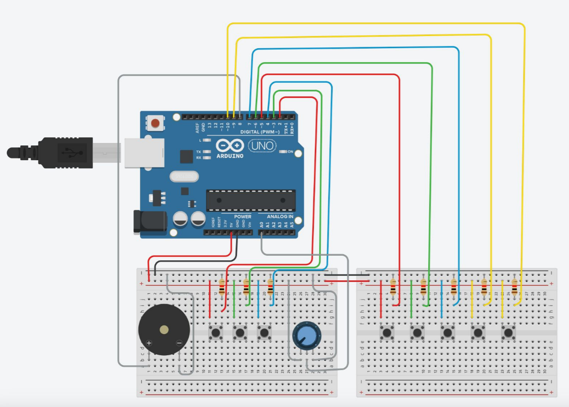
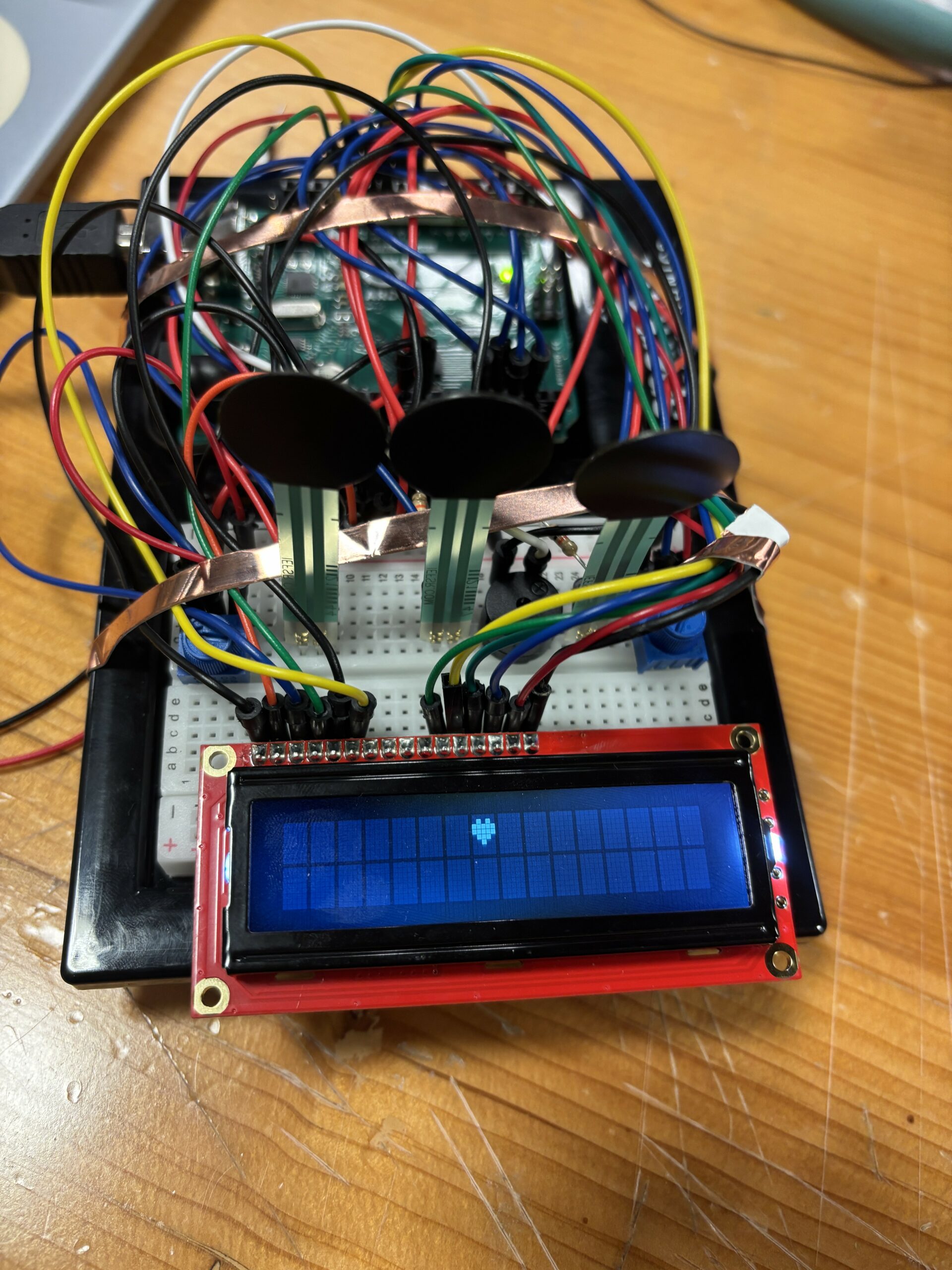
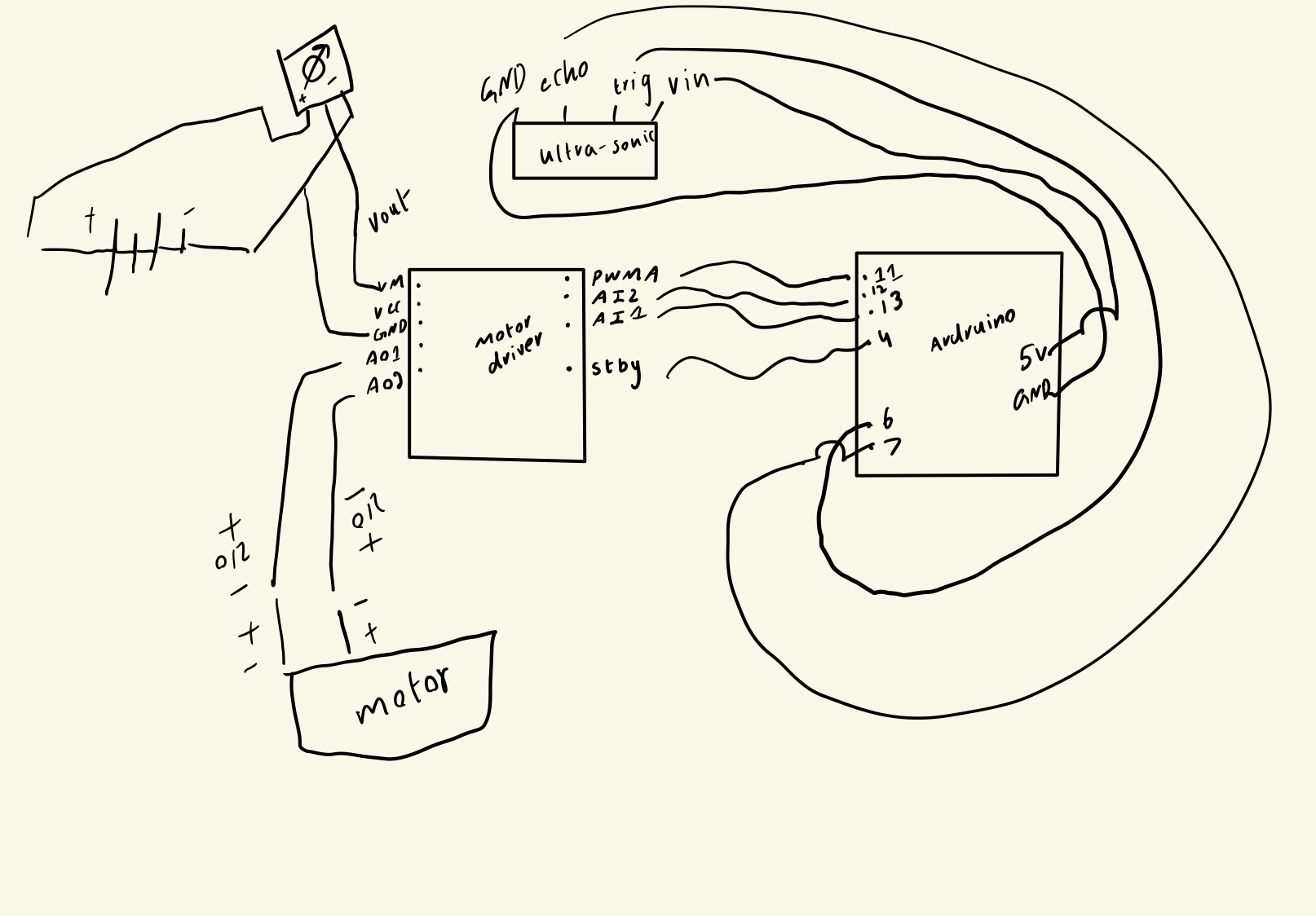
The schematic shows the connection between the components

The voltage for motors is taken in from Vout of potentiometer, and the voltage to power and ground the ultra-sonic sensor is taken in from the ardruino itself. Rest of the port – pin mapping is shown on the schematic.

The code:

//pin declaration H-bridge
#define PWMA 11
#define AIN1 13
#define AIN2 12
#define STBY 4
// Pin declaration Ultra-sonic sensor
#define TRIG_PIN 6
#define ECHO_PIN 7
//variables used
long duration;
int distance;

void setup() {
  // A ports of motor driver used
  pinMode(PWMA, OUTPUT);
  pinMode(AIN1, OUTPUT);
  pinMode(AIN2, OUTPUT);
  pinMode(STBY, OUTPUT);

  // Ultrasonic sensor pins
  pinMode(TRIG_PIN, OUTPUT);
  pinMode(ECHO_PIN, INPUT);

  
  Serial.begin(9600);
}

void loop() {
  // Trigger the ultrasonic sensor
  digitalWrite(TRIG_PIN, LOW);
  delayMicroseconds(2);
  digitalWrite(TRIG_PIN, HIGH);
  delayMicroseconds(10);
  digitalWrite(TRIG_PIN, LOW);

  
  duration = pulseIn(ECHO_PIN, HIGH);
  
// formulation to calculate distance
  distance = duration * 0.034 / 2;


  Serial.print("Distance: ");
  Serial.print(distance);
  Serial.println(" cm");

  
  digitalWrite(STBY, HIGH);
  // if distance less than 10 cm,
  if (distance < 10) {
    // anti-clockwise with blue led
    digitalWrite(AIN1, HIGH);
    digitalWrite(AIN2, LOW);
  } else {
    // clockwise movement with yellow led.
    digitalWrite(AIN1, LOW);
    digitalWrite(AIN2, HIGH);
  }

  //full threshold supply to PWMA pin
  analogWrite(PWMA, 255);

  delay(200); 
}

The code with if-else is shown above. The polarity for output A pins from motor-driver changes based on distance measured and stored by the ultra-sonic sensor.


Components:

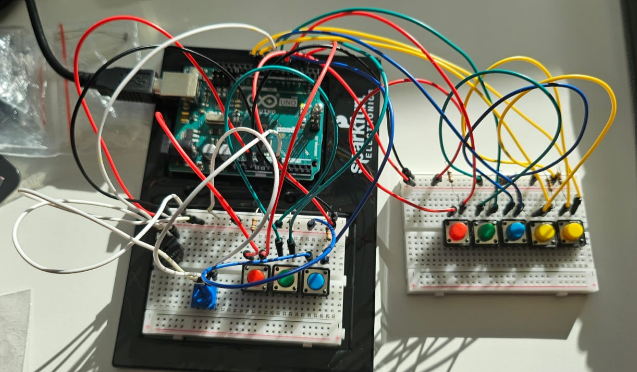
The overview of the circuit.

The H-bridge motor-driver and both leds.

The potentiometer used.

The 9V battery in use with battery cap.

Ultra-sonic sensor.

Demonstration:

Struggles and Future Improvement:

For the future improvement,  I am thinking of adding speaker, and adding resistors to prevent the motor from capping the maximum voltage fed into the motors , as well as the LEDs to prevent any damage. As for the wheelbase, while rotating, the wires of geared motor sometimes windup along with it. It stops it from rotating. Hence, I will have to redesign the canon’s base for future use.

Week 10: Musical Instrument

Description:

Vivian and I decided to create a musical instrument using force sensitive resistors (FSR) that reminded us of drumpads. There are 3 resistors in total, and each represents a different octave. Moreover, if you touch multiple at the same time you again get different octaves. There are different combinations you can try, totaling to 7 altogether. These FSR are used as digital inputs in this case, but we have a potentiometer that moves you along the scale within each octave. By turning the potentiometer, you get the full range of an octave, and by touching the FSR, you get different octaves. We also use an LCD screen to visually represent what you’re playing. Each octave has its own symbol/emoji on the screen and depending on the note you’re playing, the emoji slides across the screen. The higher the note, the farther across the screen it slides.

Video Demonstration:

video demonstration

Image of circuit:

Difficulties:

At first, we wanted to use the FSR as analog inputs and attempted many ideas of using it, but ended up on this method of using them as digital inputs because we liked that you can make different combinations. The FSR reminded us of drumpads, which is why we chose them. We also tried soldering the FSR to wires to make them easier to connect to the breadboard, but that ended up taking way too long, so we just stuck them directly to the breadboard.

We ended up using many wires and at some point, our breadboard became a bit overcrowded, and there was one time when we didn’t realize that one of the resistors was connected to 5V instead of GND.

To detect whether or not someone touched the FSR at first, we checked whether or not the reading was above 0, but realized quickly that even without touching the FSR, it was rarely ever 0. It teetered on values just above 0, so we instead used a threshold of 100.

Another huge problem we encountered in one of our past ideas was using multiple speakers at the same time. We were going to have each FSR correspond to their own speaker, but found out that the tone function doesn’t allow for multiple outputs.

Code Snippets:

Printing the custom emojis:

// make some custom characters:
byte Heart[8] = {
0b00000,
0b01010,
0b11111,
0b11111,
0b01110,
0b00100,
0b00000,
0b00000
};
// LCD screen
if (lastPotInd != potInd) {
  lcd.clear();
}
lcd.setCursor(potInd, 0);
lcd.write(byte(melodyInd));

2D array of notes:

int melody[7][12] = {
  {NOTE_C1, NOTE_CS1, NOTE_D1, NOTE_DS1, NOTE_E1, NOTE_F1, NOTE_FS1, NOTE_G1, NOTE_GS1, NOTE_A1, NOTE_AS1, NOTE_B1},
  {NOTE_C2, NOTE_CS2, NOTE_D2, NOTE_DS2, NOTE_E2, NOTE_F2, NOTE_FS2, NOTE_G2, NOTE_GS2, NOTE_A2, NOTE_AS2, NOTE_B2},
  {NOTE_C3, NOTE_CS3, NOTE_D3, NOTE_DS3, NOTE_E3, NOTE_F3, NOTE_FS3, NOTE_G3, NOTE_GS3, NOTE_A3, NOTE_AS3, NOTE_B3},
  {NOTE_C4, NOTE_CS4, NOTE_D4, NOTE_DS4, NOTE_E4, NOTE_F4, NOTE_FS4, NOTE_G4, NOTE_GS4, NOTE_A4, NOTE_AS4, NOTE_B4},
  {NOTE_C5, NOTE_CS5, NOTE_D5, NOTE_DS5, NOTE_E5, NOTE_F5, NOTE_FS5, NOTE_G5, NOTE_GS5, NOTE_A5, NOTE_AS5, NOTE_B5},
  {NOTE_C6, NOTE_CS6, NOTE_D6, NOTE_DS6, NOTE_E6, NOTE_F6, NOTE_FS6, NOTE_G6, NOTE_GS6, NOTE_A6, NOTE_AS6, NOTE_B6},
  {NOTE_C7, NOTE_CS7, NOTE_D7, NOTE_DS7, NOTE_E7, NOTE_F7, NOTE_FS7, NOTE_G7, NOTE_GS7, NOTE_A7, NOTE_AS7, NOTE_B7}
};

Mapping potentiometer value to an array index:

potInd = map(potReading, 0, 1000, 0, 12);

Logic for changing the octaves using FSR combos and selecting correct array index:

// all 3
if (fsrReading1 > 100 && fsrReading2 > 100 && fsrReading3 > 100) {
  melodyInd = 5;
}

Future Improvements:

Next time, we want to find a way to make the FSR lie flat on a surface so touching them feels more intuitive and more like a drumpad. We can also try controlling different factors about the sounds like the volume. We can also make the note progressions more predictable so that users can go through different notes more easily and play an actual song.

Reading Reflection – Week 10

Through the painting class I am taking this semester, I am constantly learning to appreciate how rich the drawing experience is using a variety of different brushes and mediums and canvases, which makes it worlds apart from painting digitally using just a stylus. Different brushes have different handle lengths, width and feels, and depending on each of these factors combined with the type of texture I am aiming to create, I have to change my grip on the brush to create the stroke I want. Though painting is something we are all taught from a very young age, I realized I have never fully paid attention to the rich combination of grips and positions that my fingers take on unconsciously while holding the brush.

This is exactly what Bret brings to our attention through his written piece — the human hand is an extraordinary tool that can do extraordinary things. It is pitiful that the interfaces which are inevitably becoming essential parts of our daily lives strip down the magic of our bodies and reduces interaction to mere swiping and tapping. Though haptics and sensory feedback mechanisms are being incorporated into touch-screen devices, we are still far from having a truly dynamic interface that fully utilizes the human sensory capabilities and the richness of hand movements, even after 14 years of the publication of Bret’s writing. As Bret writes, the first step to solving the problem is to become aware of it in the first place. We all need to start recognizing the limitations of our current interfaces and start thinking out of the box — humans created airplanes and space rockets so I am sure that, if we start ideating, infusing our diverse lived experiences, coming together, we can create dynamic interfaces that employs more than just a single finger.

Week 10 – Reading Response

Bret Victor’s “A Brief Rant on the Future of Interaction Design” calls out future interfaces to be mere pictures under glass. He argues that this approach is ignoring the amazing capabilities of the human hands. Current trends focus too much on visual interactions, neglecting our sense of touch. Hands are powerful tools for a sense of dexterity and manipulation, something currently absent in a lot of touch based technologies. He takes inspiration from Alan Key’s early vision of the iPad, and encourages designers to explore our mediums that can potentially improve user experiences by engaging us both visually and sensually. A lot of his argument actually makes sense. It is human nature, from being babies to be attracted to bring screens, but our immediate reaction to anything is to touch it, see if it turns, or moves, or if its a switch or a knob. We always seek some sense of physical manipulation in objects, and I do think modern technologies are limiting this to a far more visual approach. Even when I type essays, I prefer using a laptop keyboard over my iPad screen, because I genuinely like the touch-and-feel of clicking and clacking on the keyboard keys- it somehow motivates me to write better. Even though this isn’t a full usage of hands and body movements, this minute degree of change in physical interaction itself makes me more interested. “With an entire body at your command, do you seriously think the Future Of Interaction should be a single finger?” – this statement really opened my eyes to how much technology has been reshaped to fit users to a limited physical experience. 

In the response article, he answers some of the questions people had. I can admit that I too was unsure of the stylus situation. And I’m not sure how styluses can be made to be dynamic. I fully agree with him on the voice input part- I never found that to be appealing or better. Overall, I’d say Vistor’s rant on the future of interaction design is completely justifiable- to be futuristic doesn’t mean to be deprived of sensuality. Rather embracing the movements of our hands and channeling a sense of physical interaction can definitely aid us in improving the future of interaction.


week 9- reading assignment

physical computing:

The piece helped me realize that physical computing isn’t just about coding and hardware, it’s about designing meaningful experiences. The idea that interaction is a two way conversation made me see the importance of listening to users through how they react to what I build. It encouraged me to think more deeply about how the physical form and behavior of a project guide people without needing explanations.

interactive art:

This reading made me rethink what it means to create interactive art. Instead of focusing on showing my message, I should focus more on creating an environment where others can explore and make meaning themselves. It challenged my habit of controlling the viewer’s experience and reminded me that real interaction only happens when I let go of control and simply observe how people engage with the work.

week 9- sensor assignment

Concept
Sometimes in the UAE sunlight levels are pretty strong and sometimes harmful, so I created this project to help people know whether it is safe to go outside based on how bright the sunlight is. It uses an LDR to measure how strong the light is. If the light level is too high, a red LED turns on to show that it might be unsafe due to strong sunlight. If the light is at a normal or low level, a green LED turns on to show it is safe. The system only works when a button is pressed, giving the user control over when to check.

Implementation and Setup
To build the project, I used an LDR sensor, a push button, two LEDs (red and green), and some resistors. The LDR is connected to analog pin A0 to measure light. The button is connected to digital pin 11, and the LEDs are connected to pins 3 and 5. When the button is held down, the Arduino reads the light level. If it is above the threshold of 900, the red LED turns on meaning the sunlight levels are too high. If it is below, the green LED turns on, so the light levels are safe. I also used the Serial Monitor to display the light values for testing.

Code:

const int ldrPin = A0; // LDR sensor
const int buttonPin = 11; // push button
const int redLED = 3; // red LED (too bright)
const int greenLED = 5; // green LED (safe to go out)
const int threshold = 900; // brightness threshold

void setup() {
  pinMode(redLED, OUTPUT);
  pinMode(greenLED, OUTPUT);
  pinMode(buttonPin, INPUT);
  Serial.begin(9600);
}

void loop() {
  int lightValue = analogRead(ldrPin); // get light level
  int buttonState = digitalRead(buttonPin); // read button
  Serial.println(lightValue);
  // Serial.println(buttonState); //// to check button

  // only run if button is pressed
  if (buttonState == HIGH) {
    if (lightValue > threshold) { // if light value above threshold red LED on
      digitalWrite(redLED, HIGH);
      digitalWrite(greenLED, LOW); // green LED off
    } else {
      digitalWrite(redLED, LOW); // red LED off if light value below threshold
      digitalWrite(greenLED, HIGH); // green LED on
    }
  } else { // else both LEDS are off
    digitalWrite(redLED, LOW);
    digitalWrite(greenLED, LOW);
  }

  delay(100); // delay
}

Video:

IMG_0851

Future Improvements or Reflection
In the future, I could add a UV sensor to measure sunlight more accurately, since the LDR only measures brightness, not UV levels. I could also add a small screen or buzzer to make the warnings more clear.

Week 9 – Digital + Analog Sensors

1. Concept

I was inspired by gloves from the creative reading “Physical Computing’s Greatest Hits (and misses)” to go for a project that involves specific responses for ways of movements. Being excited about the freedom of flight, I wanted to incorporate flight. I had two parts related to flight with me, a gyroscope (measuring rotation rates) and a barometer (measuring altitude) which were, by the definitions of the IM technical readings, analog (although it does use I2C which converts analog to digital). I incorporated a slide switch as digital sensor.

2. Highlights

I attached some popsicle sticks to the breadboard to express more clearly the idea of an airplane or jet. I used red LEDs specifically as indicators for warning.

In order to figure out how to wire up and code, I researched online and found the following resources valuable in the process of building my circuit and code:

  • https://www.instructables.com/How-to-Connect-MPU6050-to-Arduino-UNO/
  • https://www.electronicwings.com/arduino/mpu6050-interfacing-with-arduino-uno
  • https://components101.com/sensors/gy-bmp280-module
  • https://www.instructables.com/Slide-Switch-With-Arduino-Uno-R3/
  • https://projecthub.arduino.cc/SurtrTech/bmp280-measure-temperature-pressure-and-altitude-6002cd

The technical and creative work with code was in combining codes for the different components together, adjusting any pin numbers, and adding conditions for the LEDs to turn on.

I encountered major obstacles in both hardware and software:

  • I mistakenly thought the BMP-280 was a BME-280. Thus, I downloaded the wrong library for the BME-280. Reading this website made me realize that my component looked similar, and I had a strong inclination that towards the sensor being a BMP-280 based on the letters of the acronyms in the sensor that it referred to BMP (BM, ME / ).
  • Initially, I connected SCL and SDA of the pressure sensor to the analog pins A4 and A5. However, readings from the pressure sensor were not appearing. I tried to replace wires thinking they were faulty, but that didn’t work. I tried to connect the wires to the SCL and SDA on the Arduino UNO but probably because I used the wrong library (BME-280), even though wiring for pressure sensor, I did not see it work (readings from the pressure sensor were not appearing).
  • My circuit was wired up in the wrong order. The SCL and SDA from the gyroscope was correctly wired to the SCL and SDA of the pressure sensor, but the SCL and SDA of the pressure sensor should have been wired to the Arduino UNO, rather than the SCL and SDA of the gyroscope directly wired to the Arduino UNO.

3. Video

4. Reflection and ideas for future work or improvements

Overall, I am glad I learned much on the technical side of things. Improvements include incorporating a buzzer like in the sound of an aircraft to warn the pilot, incorporating a radio system with other “airplanes” to warn other airplanes of being in their vicinity with the other “airplane” having its warning light prompted.

Analog input & output

Concept

For this project, I tried to build a simple lighting system using an LDR (light sensor), a push-button, and two LEDs. One LED changes brightness depending on how bright the room is, and the other lights up to show when I’ve manually taken control.

I wanted to manually override the automatic light control with the press of a button—so if I want the light to stay at a fixed brightness no matter how bright it is outside, I just hit the button. Press it again, and the automatic behavior comes back.

I used TinkerCad for the circuit simulation.

Video

How It Works

    1. The LDR is connected to pin A0 and tells the Arduino how bright the environment is.

    2. Based on this reading, the Arduino maps the value to a number between 0 and 255 (for LED brightness).

    3. The LED on pin 9 gets brighter when it’s dark and dims when it’s bright—automatically.

    4. I also wired a button to pin 2. When I press it, the system switches to manual mod

      • In this mode, the LED stays at medium brightness, no matter the light level.

      • An indicator LED on pin 13 lights up to let me know I’m in manual mode.

    5. Pressing the button again switches back to automatic mode.

Code

// Pin Definitions
const int ldrPin = A0;         // LDR sensor connected to A0
const int buttonPin = 2;       // Push-button connected to digital pin D2
const int pwmLedPin = 9;       // PWM LED for the ambient light effect
const int overrideLedPin = 13; // Digital LED for manual override indicator

// Variables
bool manualOverride = false;   // Tracks if the override mode is active
int lastButtonState = LOW;     // With external pull-down, default is LOW
unsigned long lastDebounceTime = 0;
const unsigned long debounceDelay = 50; // Debounce time in milliseconds

void setup() {
  pinMode(ldrPin, INPUT);
  pinMode(buttonPin, INPUT);
  pinMode(pwmLedPin, OUTPUT);
  pinMode(overrideLedPin, OUTPUT);
  
  // Start with manual override off, LED off
  digitalWrite(overrideLedPin, LOW);
  Serial.begin(9600);
}

void loop() {
  // Read the LDR Sensor
  int ldrValue = analogRead(ldrPin);
  
  // Map the LDR value to PWM brightness (0-255).
  // Darker environment (low ldrValue) yields a higher brightness.
  int pwmValue = map(ldrValue, 0, 1023, 255, 0);
  
  // Handle the Push-Button for Manual Override with Debouncing
  int reading = digitalRead(buttonPin);
  if (reading != lastButtonState) {
    lastDebounceTime = millis();
  }
  if ((millis() - lastDebounceTime) > debounceDelay) {
    //Unpressed = LOW, pressed = HIGH.
    if (reading == HIGH && lastButtonState == LOW) { // button press detected
      manualOverride = !manualOverride;
      // Update the indicator LED accordingly
      digitalWrite(overrideLedPin, manualOverride ? HIGH : LOW);
    }
  }
  lastButtonState = reading;
  
  // LED Behavior Based on Mode 
  if (manualOverride) {
    // In manual override mode, set LED to a fixed brightness.
    analogWrite(pwmLedPin, 128);
  } else {
    // Set brightness according to ambient light measured by the LDR.
    analogWrite(pwmLedPin, pwmValue);
  }
  
  // Debug output
  Serial.print("LDR Value: "); Serial.print(ldrValue);
  Serial.print(" | PWM Brightness: "); Serial.print(pwmValue);
  Serial.print(" | Manual Override: "); Serial.println(manualOverride ? "ON" : "OFF");
  
  delay(10);
}

Challenges

    • Balancing Automatic and Manual Modes:
      Getting the right balance between automatic brightness adjustments and a satisfying manual override was a fun challenge. I had to fine-tune the mapping of LDR readings to PWM values until the LED’s response felt right in different lighting conditions.

    • Debugging with Serial Monitor:
      Utilizing the Serial Monitor was incredibly useful. Every time something wasn’t working as expected, I added more Serial prints to understand what was happening.