Task 1: Horizontal Movement of Ellipse
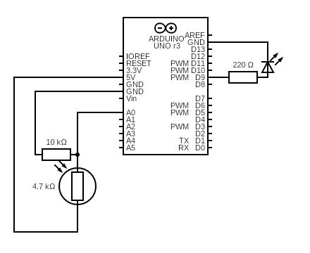
In this setup, I connected a photoresistor to analog pin A0 of the Arduino. The changing light levels (e.g., when I moved my hand closer or farther) were read via analog input and sent to p5.js over serial communication. In p5.js, the light level was mapped to a horizontal position (X-axis) of an ellipse on screen.
As a result, the ellipse smoothly moved left to right based on how much light was detected by the sensor. The Arduino was a pure input device in this task, with no output components involved.
// Arduino Code for Photocell -> Horizontal Ellipse
const int photoPin = A0;

void setup() {
  Serial.begin(9600);
}

void loop() {
  int lightLevel = analogRead(photoPin);
  Serial.println(lightLevel);
  delay(50);  // small delay for stability
}
//Javascript:

let serial;
let latestData = "0";

function setup() {
  createCanvas(400, 400);

  serial = new p5.SerialPort();
  serial.open("/dev/tty.usbmodem13301");
  serial.on("data", () => {
    latestData = serial.readLine().trim();
  });
}

function draw() {
  background(220);
  let x = map(Number(latestData), 0, 1023, 0, width);
  ellipse(x, height/2, 50, 50);
}
Task 2: LED Brightness Controller
This task reverses the direction of interaction from Task 1. A slider on the p5.js canvas sends values (0–255) to Arduino via serial. The Arduino reads these values and writes them to a PWM pin controlling an LED, adjusting brightness in real-time.
As a result, once the slider was adjusted, the LED smoothly brightened or dimmed, creating a tangible link between screen-based and physical interaction.
// Arduino Code for LED brightness control
const int ledPin = 9;

void setup() {
  pinMode(ledPin, OUTPUT);
  Serial.begin(9600);
}

void loop() {
  if (Serial.available()) {
    int brightness = Serial.parseInt();
    analogWrite(ledPin, brightness);
  }
}
//Javascript

let serial;
let slider;

function setup() {
  createCanvas(400, 200);
  slider = createSlider(0, 255, 127);
  slider.position(20, 20);

  serial = new p5.SerialPort();
  serial.open("/dev/tty.usbmodem13301");
}

function draw() {
  background(255);
  let val = slider.value();
  text("Brightness: " + val, 20, 70);
  serial.write(val + "\n");
}
Task 3: Bouncing Ball
For this task, I modified the Gravity + Wind example from p5.js. A photocell connected to Arduino reads ambient light and sends it to p5.js to control the “wind” vector pushing up on the ball. Simultaneously, when the ball hits the bottom of the canvas, p5.js sends a “BOUNCE” signal back to Arduino, briefly lighting up an LED.
In the end, the ball was bouncing realistically, with its movement affected by how much I covered the photocell. Each bounce triggered a short LED flash, adding physical feedback to a digital interaction.
// Alternate: if p5 sends a "bounce" message, flash LED
const int ledPin = 9;
const int photoPin = A0;

void setup() {
  pinMode(ledPin, OUTPUT);
  Serial.begin(9600);
}

void loop() {
  int light = analogRead(photoPin);
  Serial.println(light);
  delay(10);

  if (Serial.available()) {
    String command = Serial.readStringUntil('\n');
    if (command == "BOUNCE") {
      digitalWrite(ledPin, HIGH);
      delay(100);
      digitalWrite(ledPin, LOW);
    }
  }
}
//Javascript

let serial;
let position, velocity, acceleration;
let gravity, wind;
let drag = 0.99;
let mass = 50;
let photoresistorValue = 0;

function setup() {
  createCanvas(640, 360);
  position = createVector(width / 2, 0);
  velocity = createVector(0, 0);
  acceleration = createVector(0, 0);
  gravity = createVector(0, 0.5 * mass);
  wind = createVector(0, 0);

  serial = new p5.SerialPort();
  serial.open("/dev/tty.usbmodem13301");

  serial.on("data", () => {
    let data = serial.readLine().trim();
    if (!data) return;
    photoresistorValue = int(data);
  });
}

function draw() {
  background(255);

  wind.y = map(photoresistorValue, 0, 1023, -2, 0);  // More wind when covered

  applyForce(gravity);
  applyForce(wind);

  velocity.add(acceleration);
  velocity.mult(drag);
  position.add(velocity);
  acceleration.mult(0);

  // Bounce
  if (position.y > height) {
    position.y = height;
    velocity.y *= -1;
    serial.write("BOUNCE\n"); // Trigger LED
  }

  ellipse(position.x, position.y, 50, 50);
}

function applyForce(force) {
  let f = p5.Vector.div(force, mass);
  acceleration.add(f);
}
Reflection:
This set of projects helped me understand both unidirectional and bidirectional interactions between hardware and software. The exercises showed how to turn real-world stimuli into digital visuals and vice versa, laying the groundwork for interactive installations, responsive art, or assistive interfaces, which is a great practice for the final project.
Reading Assignment
Reading Design Meets Disability made me rethink how design often treats disability as something to minimize or fix, rather than as an opportunity for creative expression. Pullin’s argument that assistive technologies like hearing aids or prosthetics can be expressive and personal, not just functional has really stuck with me. It challenged the default idea in my head that good design is neutral or invisible, and instead made me see how thoughtful design can actually expand what’s possible for people with disabilities.
This reminded me of Sophie de Oliveira Barata’s work, which we studied in my Communication and Technology class. Through the Alternative Limb Project, she creates prosthetics that are more than medical devices but rather artistic statements. Some are realistic, others are completely imaginative, with embedded lights or sculptural elements. Her work makes it clear that prosthetics can reflect someone’s identity and creativity, not just their physical needs. It’s a powerful example of how design can shift the narrative from limitation to self-expression.
Both Pullin’s book and Sophie’s work pushed me to question what we mean by “inclusive” or “accessible” design. It made me realize that good design goes beyond functionality by also giving people choices, visibility, and agency. I’m beginning to see inclusive design not as a constraint, but as a more thoughtful and exciting way to approach creative work.