
Candy Canon
Introduction:
Candy Canon was an idea born from the movie ‘Wreck it Ralph’ where he ends up sneaking into a candy kingdom. Therein the movie, exists a canon that shoots out candy. Having seen the movie recently, I decided to build a prototype after it.

Concept and implementation:
For this assignment, we were tasked to make use of two LEDs , a digital sensor (switch), and an analogue sensor – one of each used at the very least. Given the requirement, I re-used the card-board canon I made by re-using the cardboard boxes lying around inside the IM lab. The canon was ok to use, and underneath inthere, the base was attached to a wheel and a 48:1 ratio geared motor. That motor would be controlled by 9 V battery with potentiometer adjusting the voltage fed in to a safer level. The potentiometer would start and speed up the rotation of the motor, hence that of the canon. The bulb will be connected in parallel to plates on breadboard carrying the output for the geared motor. The Yellow Led is alligned with polarity of geared motor when it rotates clockwise, and that of blue when it rotates anti-clockwise. Cleverly, the forward bias property of these diodes were used. Hence only one led would light up when the polarity matches its poles. The output from H-bridge motor driver would change when the ultra-sonic sensor would detect an object close to it or not. Hence the polarity of output can be changed, with H-bridge outputs swapping poles. The H-bridge is fed external voltage by 9 Volt battery which is the source of juice for the motor.
Schematic:
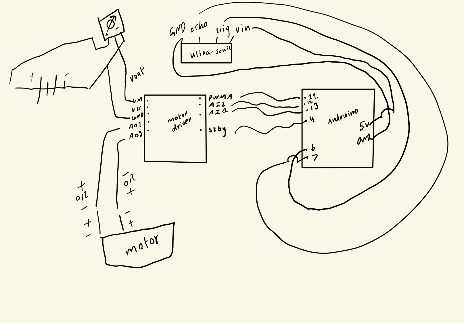 The schematic shows the connection between the components
The voltage for motors is taken in from Vout of potentiometer, and the voltage to power and ground the ultra-sonic sensor is taken in from the ardruino itself. Rest of the port – pin mapping is shown on the schematic.
The code:
//pin declaration H-bridge
#define PWMA 11
#define AIN1 13
#define AIN2 12
#define STBY 4
// Pin declaration Ultra-sonic sensor
#define TRIG_PIN 6
#define ECHO_PIN 7
//variables used
long duration;
int distance;

void setup() {
  // A ports of motor driver used
  pinMode(PWMA, OUTPUT);
  pinMode(AIN1, OUTPUT);
  pinMode(AIN2, OUTPUT);
  pinMode(STBY, OUTPUT);

  // Ultrasonic sensor pins
  pinMode(TRIG_PIN, OUTPUT);
  pinMode(ECHO_PIN, INPUT);


  Serial.begin(9600);
}

void loop() {
  // Trigger the ultrasonic sensor
  digitalWrite(TRIG_PIN, LOW);
  delayMicroseconds(2);
  digitalWrite(TRIG_PIN, HIGH);
  delayMicroseconds(10);
  digitalWrite(TRIG_PIN, LOW);


  duration = pulseIn(ECHO_PIN, HIGH);

// formulation to calculate distance
  distance = duration * 0.034 / 2;


  Serial.print("Distance: ");
  Serial.print(distance);
  Serial.println(" cm");


  digitalWrite(STBY, HIGH);
  // if distance less than 10 cm,
  if (distance < 10) {
    // anti-clockwise with blue led
    digitalWrite(AIN1, HIGH);
    digitalWrite(AIN2, LOW);
  } else {
    // clockwise movement with yellow led.
    digitalWrite(AIN1, LOW);
    digitalWrite(AIN2, HIGH);
  }

  //full threshold supply to PWMA pin
  analogWrite(PWMA, 255);

  delay(200);
}
The code with if-else is shown above. The polarity for output A pins from motor-driver changes based on distance measured and stored by the ultra-sonic sensor.
Components:
 The overview of the circuit.
 The H-bridge motor-driver and both leds.
 The potentiometer used.
 The 9V battery in use with battery cap.
 Ultra-sonic sensor.
Demonstration:
Struggles and Future Improvement:
For the future improvement, I am thinking of adding speaker, and adding resistors to prevent the motor from capping the maximum voltage fed into the motors , as well as the LEDs to prevent any damage. As for the wheelbase, while rotating, the wires of geared motor sometimes windup along with it. It stops it from rotating. Hence, I will have to redesign the canon’s base for future use.