
For this project, I decided to use a photoresistor to create a light that detects a light source nearby.
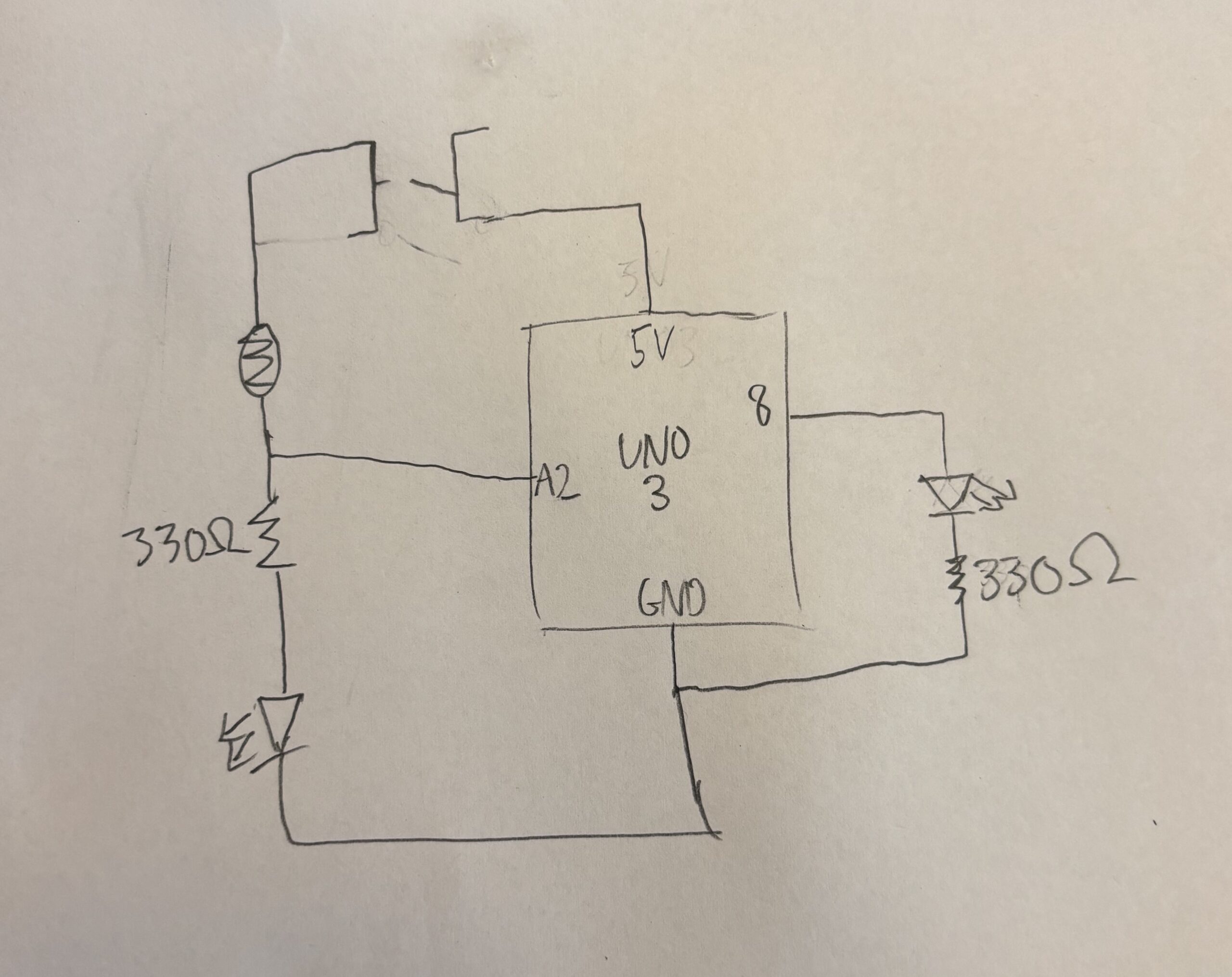
To implement this, I used two circuits; one connected to 5V power supply and another connected to the analog pins, whose power level could be controlled by the analogWrite on IDE. The circuit was not too complicated, connect a manual toggle switch to one side of the circuit, leading into a photoresistor connected to pin A2, leading into the first LED. This would mean the first LED would only light up if the switch was toggled on. This meant that we could see an indicator if the device is working. Next, connected to pin 8 the other LED was connected. This meant that we can control this LED digitally with the arduino. In the circuit, we could use the input we got from A2 to determine if power should be sent to pin 8.

int analogPin = A2;
int lightSensor;
int brightness;
void setup() {
  // put your setup code here, to run once:
pinMode(8, OUTPUT);
pinMode(A2, INPUT);
brightness = 128;

}

void loop() {
  // put your main code here, to run repeatedly:
lightSensor = analogRead(analogPin);
if(lightSensor > 500){
analogWrite(8, 1000);
} else {
analogWrite(8, 0);
}
}
The challenges were that it took a long time to make sure the code and the circuit were both correct. One being correct while the other being wrong would mean the whole thing would not work. Hence, in my making process, I took time testing the two parts individually. Initally there was some confusion on my end pertaining to the difference between analog and digital writing, as using the wrong one meant my LEDs were not lighting up.
This project could definitely be made more complex. I think adding a variety of lights and changing the different thresholds to which each individual LED would light up is a good way to make this project more useful.