
For this assignment I started by connecting one push-switch to one LED, and I used that as the basis of my draft schematic and work. I then re-drew my schematic and included the photoresistor (LDR) sensor. Here I faced challenges in both the hardware and software, specifically within the timing of the code. Initially, the light would stay on for too long, and I rechecked the timing of my Arduino code and adjusted it to be in a shorter high (on) state.
const int ldrPin = A2;              // LDR connected to analog pin A0
const int buttonPin = 2;            // Push button connected to digital pin 2
const int ledAnalogPin = 10;         // PWM LED pin
const int ledDigitalPin = 11;       // On/off LED pin

void setup() {
  pinMode(buttonPin, INPUT);
  pinMode(ledAnalogPin, OUTPUT);
  pinMode(ledDigitalPin, OUTPUT);
  Serial.begin(9600);
}

void loop() {
  int ldrValue = analogRead(ldrPin);
  int brightness = map(ldrValue, 0, 1023, 255, 0);  // This adjusts the brightness

  analogWrite(ledAnalogPin, brightness);

  int buttonState = digitalRead(buttonPin);

  if (buttonState == HIGH) {
    digitalWrite(ledDigitalPin, HIGH);
  } else {
    digitalWrite(ledDigitalPin, LOW);
  }

  delay(100);
}
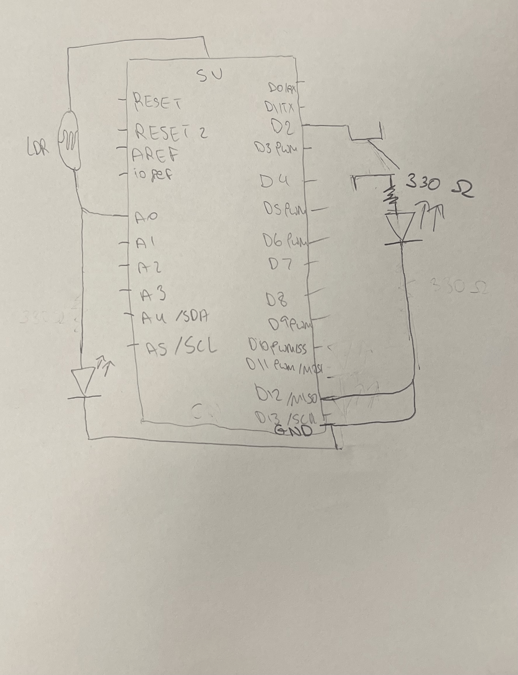
For the schematic I followed the fritz schematics format:
Video Demonstration:
https://drive.google.com/file/d/1kAYD6v6C86fbftmEfKM37j6jtumxzql1/view?usp=sharing
Some challenges I would still like to overcome and solve better are the output of the LED from the photoresistor (LDR) sensor, as I wanted the output to be stronger. I will address these issues by having a closer adherence to the schematic and a better methodology of implementing the changes to the circuit (thinking of what would happen if I added a certain connection or made a specific change before making that change).