Game Description
Dungeon Escapist is a single-player game where players take control of an adventurer and delve through a dungeon. By using a physical controller that reacts with tilting, players can move their character, collect coins, and reach the exit before the time runs out!
Project Inspiration
Dungeon Escapist is a game heavily inspired by older titles such as Adventure (1980), with interactive elements from The Legend of Zelda: Breath of the Wild (2017). This game is also a direct sequel to my previous IM game: Pyro Dancer.
Escapist (adjective)
relating to avoiding an unpleasant or boring life by thinking, reading, etc. –Cambridge Dictionary
Unlike the previous game, however, Dungeon Escapist focuses more on problem-solving rather than player reaction. The main character, an adventurer, wishes to gain riches! He began to look around the Adventurer’s Guild to see if there were commissions. Noticing the dungeon-clearing request, our protagonist sets off to explore the uncharted areas in hopes of bathing in fame and fortune.
Gameplay Images
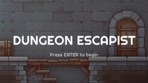 Main Menu Screen
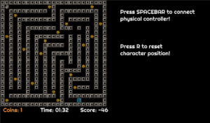
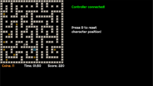 Game Screen with different maps
Gameplay Videos
How the Game Works
The game is built using the p5 Play library. The dungeon (or maze) is an array of sprites. The library can then construct these using their built-in sprite and tiling system. Because of this, the game is able to have three distinct maps easily.
// Print the sensor data to the serial monitor
//currentDirection, X, Y, Z
Serial.print(currentDirection);
Serial.print(",");
Serial.print("X:");
Serial.print(x);
Serial.print(",");
Serial.print("Y:");
Serial.print(y);
Serial.print(",");
Serial.print("Z:");
Serial.println(z);
Arduino sends out a message consisting of a number, the controllerDirection, alongside XYZ information to the Serial Output. The number listed in controllerDirection is read by p5 and moves are made based on that.
//Serial Library function
function readSerial(data) {
  ////////////////////////////////////
  //READ FROM ARDUINO HERE
  ////////////////////////////////////

  if (data != null) {
    //Only run when there is a Serial message
    let fromArduino = split(trim(data), ",");
    if (fromArduino.length == 4) {
      controllerDirection = int(fromArduino[0]);
    }
  }
}

// Then....

//UP
    if (
      controllerDirection == 12 &&
      isOpen(avatar.x, avatar.y - 1, currentMap) &&
      gameState == 1
    )
Then, inside the game, a function called isOpen() checks whether the space in the array next to the player is free. If it is and the controllerDirection is specific to that direction, the character will move infinitely towards that direction until it hits a wall. This simplicity of the character movement is something I am proud of.
function isOpen(x, y, mapName) {
  //Function to check whether the tile is empty to allow moving
  let i = floor(x);
  let j = floor(y);
  let tile = mapName[j][i];
  if (tile == "." || tile == "x" || tile == "h") {
    return true;
  } else {
    return false;
  }
}
Two major issues that I found to be painful while developing the game are figuring out the scoring system and gameState. It took me a few hours to solve why using multiple game states would crash the game. Ultimately, it all comes down to checking the game state before changing to another one.
The scoring system depends on the game time and coins picked. I wanted to make it such that the longer the player spends solving the dungeon, the less score they get, whereas the coins, act as a score multiplier. I found out that instead of immediately running the timer, I can make it run after the player has collected at least one coin.
User Testing & Feedback
During the production phase (2 & 4 May 2024), the game was tested by several users (thank you). Here are some of the issues that the game encountered:
The first thing I noticed was how players were confused about what to do with the physical controller. To combat this confusion, I decided to add a tutorial screen after the title screen. It also specifically mentions to “tilt” the physical controller for more legibility.
Notable things that I observed were in particular how long it took for players to solve the maze. Originally, I thought it would take <1 minute.
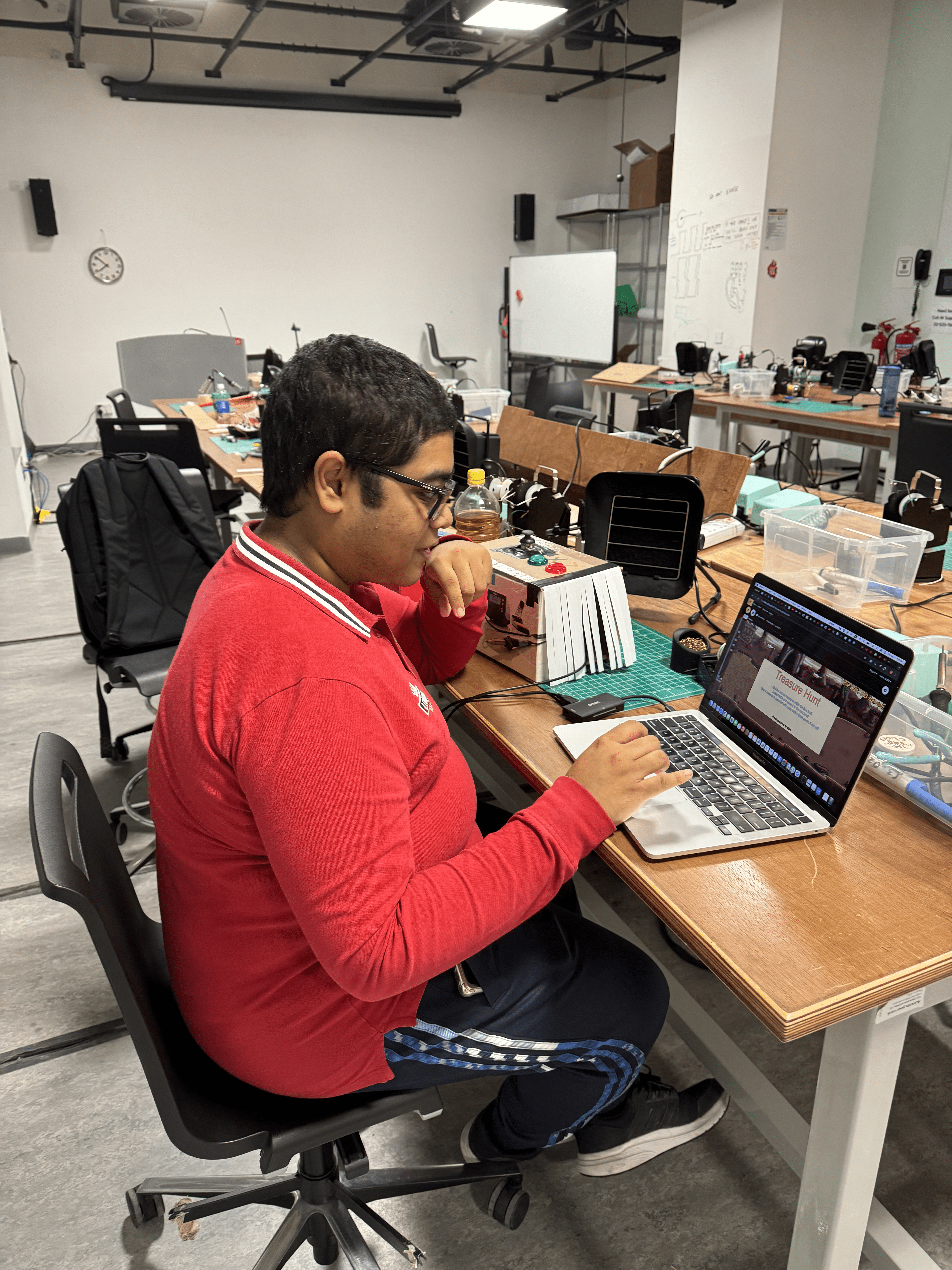
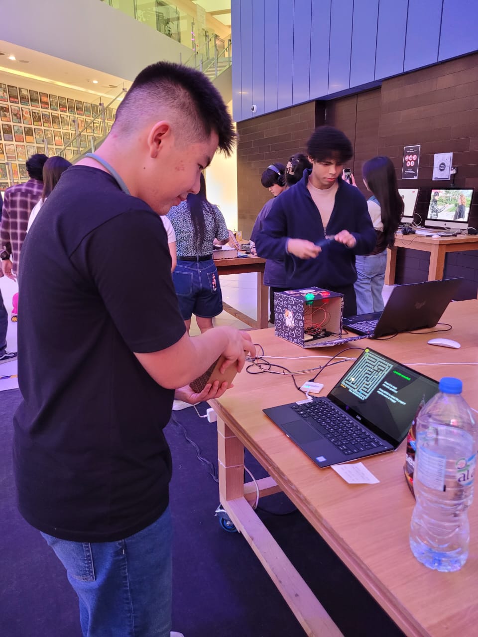
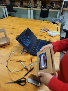 Initial User Testing.
However. given the time it takes for the player to figure out the control scheme, solve the maze, and discover things, the time averages around 4 minutes. The scoring system, which is dependent on the time and coins, has then been adjusted to give leniency to the players.
Another notable issue was player sprite color. Because it looks very similar to the walls, the color has been adjusted for better visibility as well.
I also found out that people kept referring to this game to how similar it is to a mobile game called Tomb of the Mask, a hit mobile game, due to their style.
Production Images
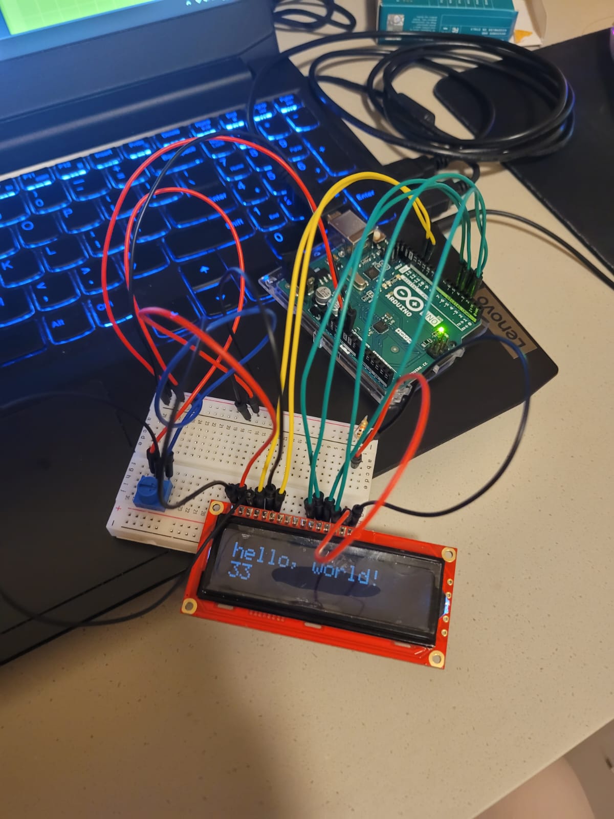
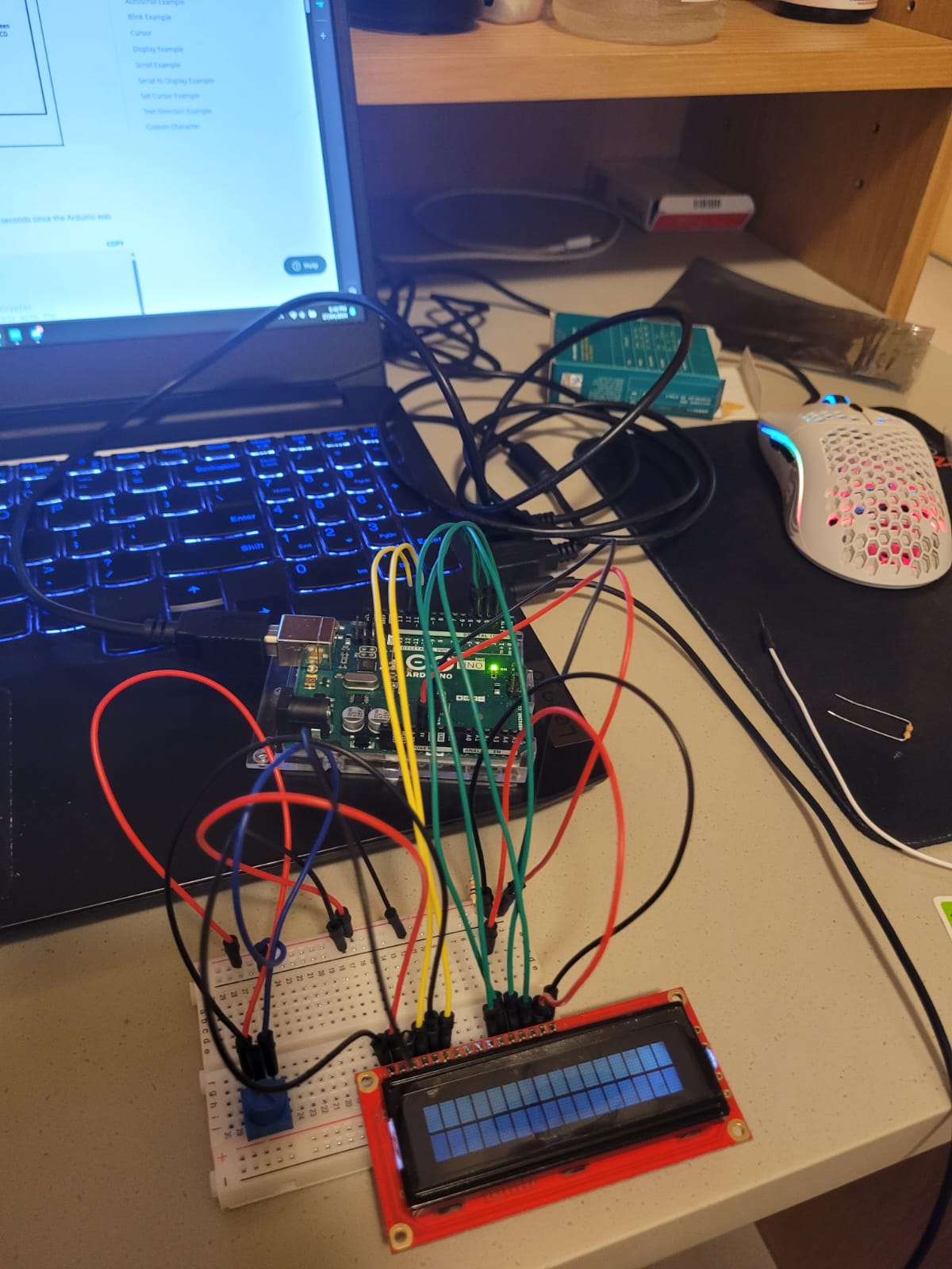
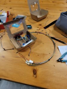 From prototypes to actual product
Future Improvements
- I originally wanted to make the physical controller pretty. However, by the time I finished the whole game, another project was waiting for me. I will try to see what I can do before the IM Show just to make things a bit more pretty.
- Scoreboards. I wanted to implement scoreboards so players could compare their scores. However, this was quite difficult to implement. So I’ll try to see what I can do in the meantime.
I.M. Show Reaction!
Many thanks to everyone who played Dungeon Escapist and managed to finish the level! Here are some thoughts, reactions, and comments about the game:
“I was confused with the controls in the beginning … It is quite difficult!” -A professor
“Pretty cool.” -I.M Senior
“It’s difficult to control in the beginning. But once you get the hang of it, it gets easier.” -A lost engineer
“Cool game. The UI/UX can be improved though” -An I.M Professor
I am glad that Dungeon Escapist captured the attention of many. I noticed that the game is ‘easier’ to grasp for younger audiences, whereas the controls and movement of the game are a barricade for adult audiences. By observing the human-machine interaction, I gathered so many insights on how to improve the game. While the difficulty might need to be adjusted, specifically in the map design, I believe the skill ceiling from mastering the physical controller of Dungeon Escapist makes it enjoyable and rewarding.
Resources Used
Assets
Royalty Free 8-Bit Background Music Downloads | FStudios (fesliyanstudios.com)
Tutorials
How to Use Gyroscopes on the Arduino – Ultimate Guide to the Arduino #43 (youtube.com)
Yes, you can make a Gyroscope using #arduino (youtube.com)
Coding Challenge #66: JavaScript Countdown Timer (youtube.com)
p5play: Using tiles, tilesets, and making pixelated background images with Photoshop (youtube.com)