Inspiration
Making a creative hands-free switch that could turn on a light inside a trash can served as the motivation for this project. The intention was to design a switch that could be activated with the foot or another body part, eliminating the need to touch the trash can with your hands. This could be useful in situations where your hands are dirty or full, and you want to avoid the spread of germs or in the case where the room is dark.
Concept
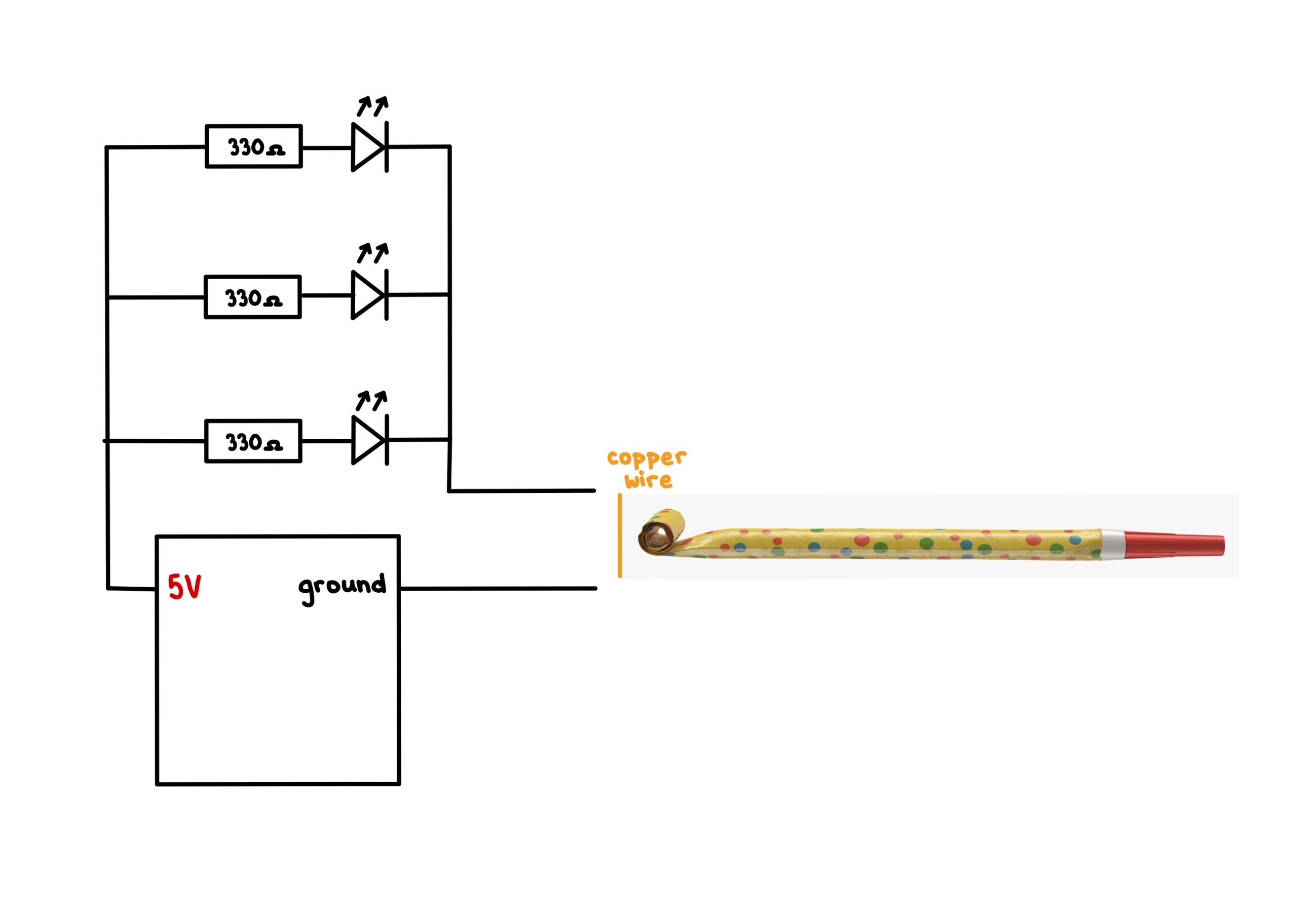
The concept for the switch was to use two pieces of aluminum foil attached to any two surfaces of the trash bin that come in contact as soon as the pedal of the trash bin is pressed. When the bin is opened, the foils come into contact, completing the circuit and allowing current to flow through an LED. The switch is powered by an Arduino board, and the LED provides visual feedback to let the user know when the switch has been activated.
Implementation
To implement the switch, I first attached two conductive aluminum foils to the lining of the trash bin, making sure they were securely attached and wouldn’t come loose over time. I then connected one wire to the positive terminal of the LED and the other wire to the positive terminal of the Arduino board (3.3V). I connected the negative terminal of the LED to the ground terminal of the board, completing the circuit.
When the trash bin is opened, the two wires come into contact, allowing current to flow through the LED and light it up. The LED provides visual feedback to the user, letting them know that the switch has been activated.
Pictures
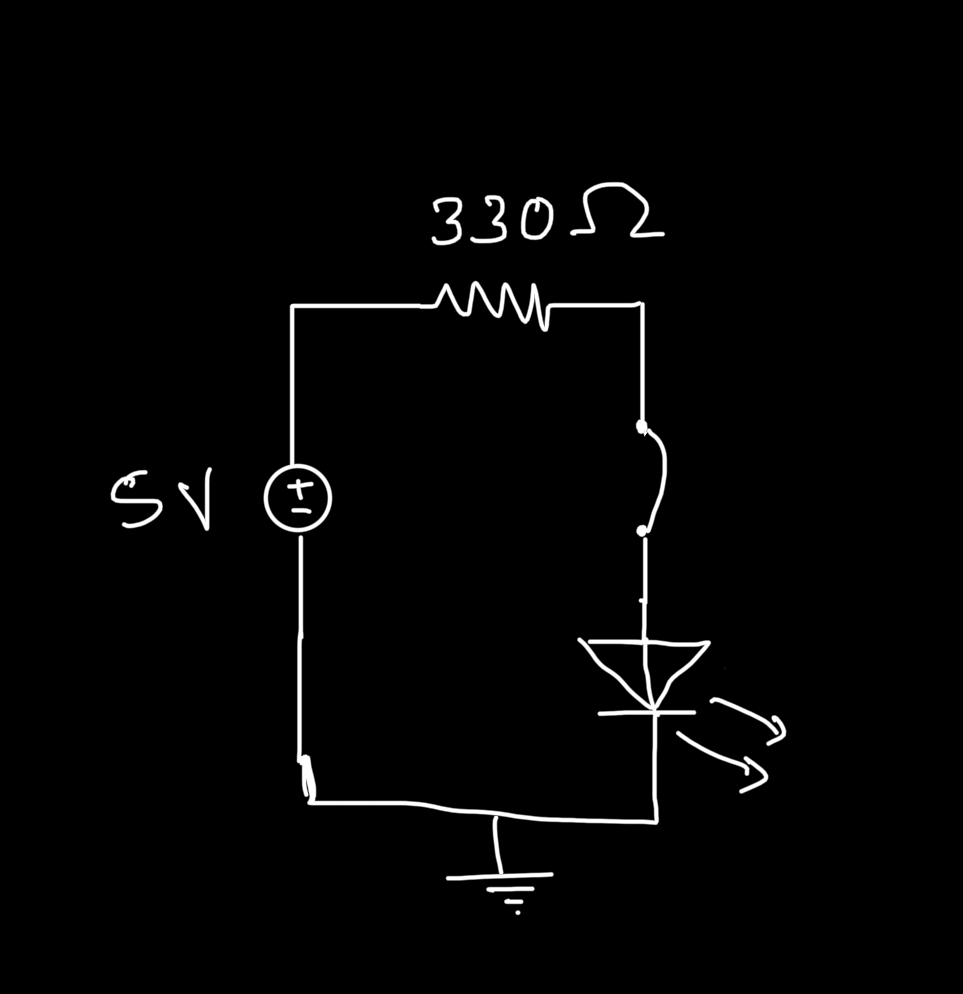
Circuit Image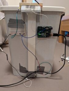

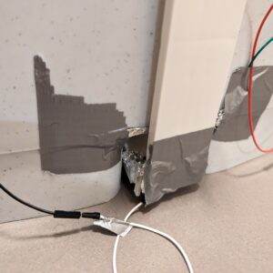
Aluminum foil plates
Challenges
One of the main challenges I faced was making sure that the conductive wires were securely attached to the lining of the trash bin. I experimented with a few different adhesives before finding one that worked well. I also tried out by putting the foil in different parts of the trash can before finally finding a place that remained completely hidden to the user and would definitely come in contact every time the bin was opened. Another challenge was making sure that the wires were positioned in such a way that they wouldn’t come into contact accidentally and complete the circuit when the switch wasn’t being used.
Reflections
I am pleased with how the switch turned out. It is simple yet effective, and it meets the goal of creating a hands-free switch for a trash bin light. I learned a lot about working with conductive materials and designing circuits, and I feel that this project could be a useful starting point for other similar projects in the future.
 Step 1
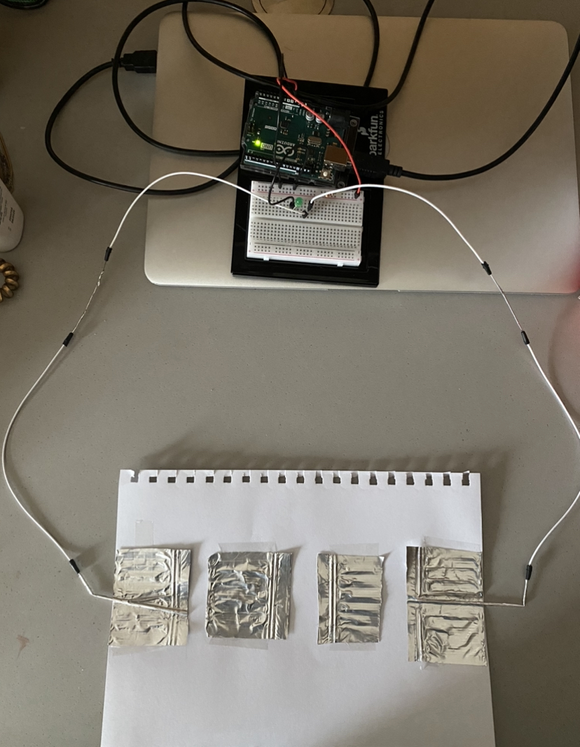 Step 2
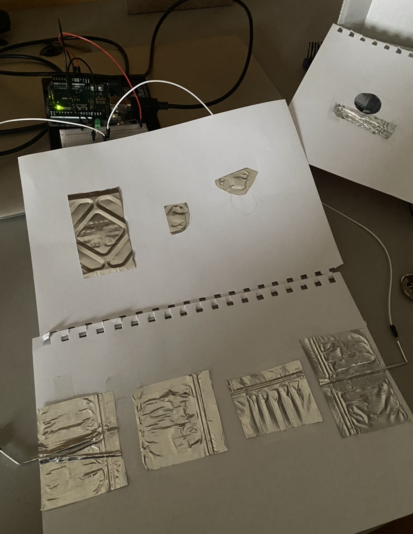 Step 3
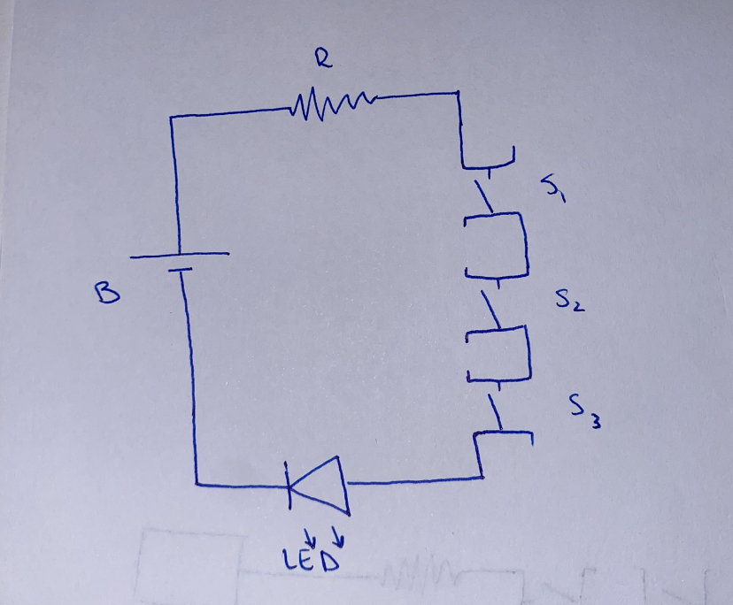 Circuit Diagram