
WEATHER PATIO
ARDUINO & PROCESSING
Done By : Shamma & Theyab
PROJECT SUMMARY:
The project is a smart outdoor cover that we called the weather patio . It has the following different features. First, the system will detect if it’s raining, and if it is then it will close the rollable roof. Second, the system measures the temperature and if the temperature is very high, it will turn on a fan. Third, it detects if it’s night time and turns on the lights when it’s dark. Fourth, it displays all the values on a screen. Last, but not least, it allows for manual control from processing on a screen, so the roof , the fan and the light can be turned on manually using the screen controls.
SYSTEM I/O:
Input:

- Rain Sensor

- Temperature Sensor

- Light Sensor
Output:

-Servo or DC Motor

-Fan DC

-LED Strip with relay
DESCRIPTION OF EACH INPUT/OUTPUT ON ARDUINO & WHAT IT WILL SEND/RECEIVE FROM PROCESSING :
Input Arduino:
-
-
-
-
Rain sensor to detect if it’s raining
-
Temperature sensor to detect the ambient temperature.
-
Light sensor to detect the light in the area.
-
-
-
Output Arduino:
-
-
-
-
Motor (servo or DC) to close and open the roof top
-
Fan to cool down the temperature
-
LED strip or bulb to add light during the night
-
-
-
Basically, all the inputs will send the data to the processing in order to be visualized on the processing screen. That allows monitoring of the temperature, rain existence and light in the area. Thus, all the outputs of the Arduino will receive control from the processing , as the system we are building will be controlled manually using the screen of processing or automatically using the Arduino code.
DESCRIPTION OF PROCESSING & WHAT IT WILL SEND/RECEIVE TO ARDUINO:
Processing is used for two main reasons:
-   Monitor the values given by the temperature sensor and other sensors.

-   Allow for manual control of the outputs. As we will add buttons on the screen to be able to turn on/off the outputs when we need regardless of the value.
The manual control is needed as sometimes even it is not raining we might want to close the roof top. Or even turn on / off the fan regardless if it’s too hot, even turn on and off the light regardless of the time of the day.
PROCEDURE:
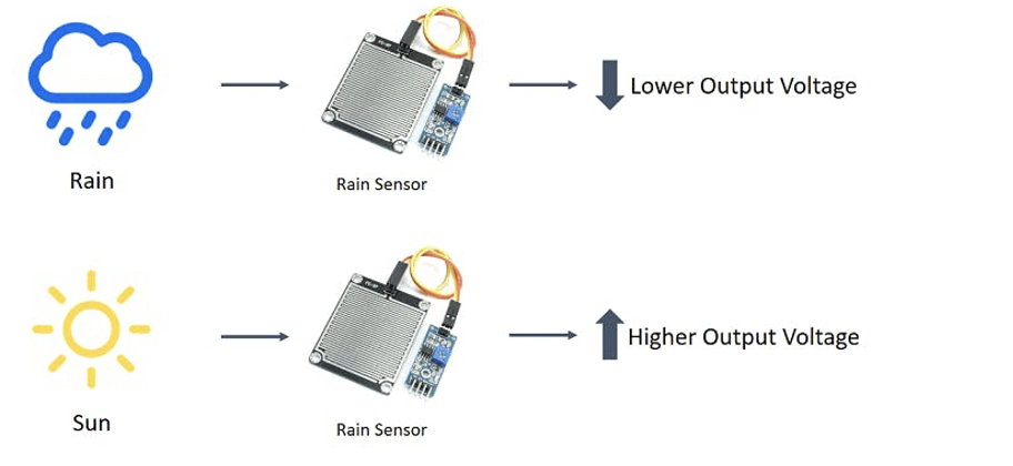
RAIN FALL SENSOR:
The rain sensor detects water that comes short circuiting the tape of the printed circuits.

The sensor acts as a variable resistance that will change status : the resistance increases when the sensor is wet and the resistance is lower when the sensor is dry.
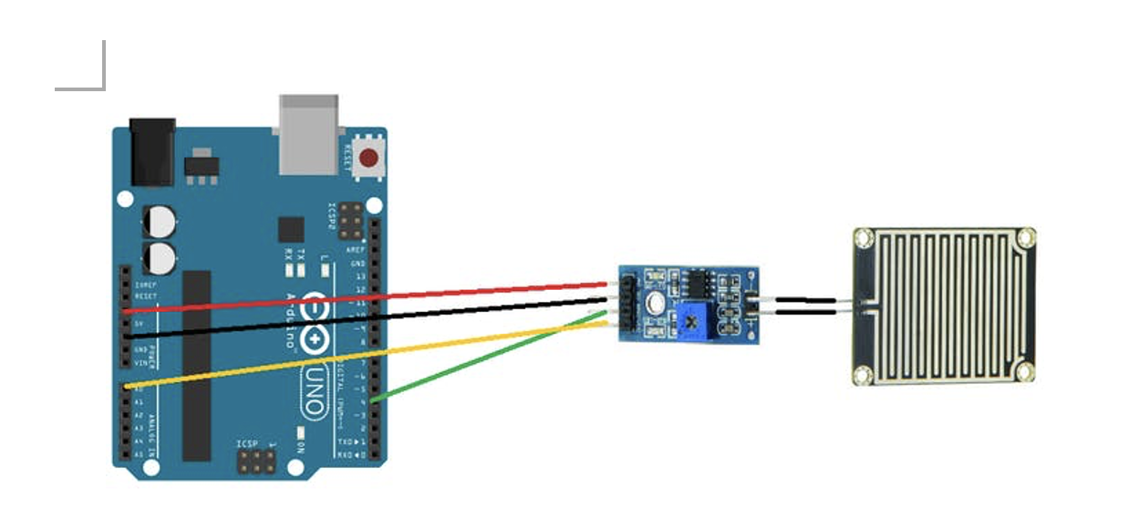
Connection:
Arduino –> Comparator
5V –> VCC
GND –> GND
DO –> D4
AO –> A0
Blueled ->pin 3
A blue LED is connected to show the presence of rain. If it’s raining, the blue LED will turn on, if it’s not raining the blue LED is off.
Code of Rain Sensor :
//RAINFALL SENSOR CODE
const int capteur_D = 4;
const int capteur_A = A0;
int blueled=2;
int val_analogique;
void setup()
{
  pinMode(capteur_D, INPUT);
  pinMode(capteur_A, INPUT);
  pinMode(blueled, OUTPUT);
  Serial.begin(9600);
}
void loop()
{
if(digitalRead(capteur_D) == LOW)
  {
    Serial.println("Digital value : wet");
    delay(10);
    digitalWrite(blueled,HIGH);
  }
else
  {
    Serial.println("Digital value : dry");
    delay(10);
    digitalWrite(blueled,LOW);
  }
val_analogique=analogRead(capteur_A);
 Serial.print("Analog value : ");
 Serial.println(val_analogique);
 Serial.println("");
  delay(1000);
}
LIGHT SENSOR:
LDR light dependent resistor to have an automatic light turn on when it’s dark.
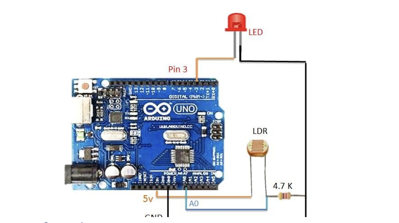
Connection
LDR: one side to 5V, other pin to analog pin A1 and to a 4.7K resistor connected to GND.

Output: LED on pin 3
Code with LDR:
const int capteur_D = 4;
const int capteur_A = A0;
int blueled=2;//for rain
int val_analogique;
int LDRsensorPin=A1;
int LDRsensorValue = 0;
int greenled = 3;//green light for ldr
void setup()
{
  pinMode(capteur_D, INPUT);
  pinMode(capteur_A, INPUT);
  pinMode(blueled, OUTPUT);
  pinMode(greenled, OUTPUT);
  Serial.begin(9600);
}

void loop()
{
if(digitalRead(capteur_D) == LOW)
  {
    Serial.println("Digital value : wet");
    delay(10);
    digitalWrite(blueled,HIGH);
  }
else
  {
    Serial.println("Digital value : dry");
    delay(10);
    digitalWrite(blueled,LOW);
  }
val_analogique=analogRead(capteur_A);
 Serial.print("Analog value : ");
 Serial.println(val_analogique);
 Serial.println("");
 LDRsensorValue = analogRead(LDRsensorPin);
 if(LDRsensorValue < 600)
 {
   Serial.println("LED light on");
   digitalWrite(greenled,HIGH);Serial.println(LDRsensorValue);
   //delay(1000);
 }
 else {digitalWrite(greenled,LOW);Serial.println(LDRsensorValue);}
  delay(1000);
TEMPERATURE SENSOR & FAN:
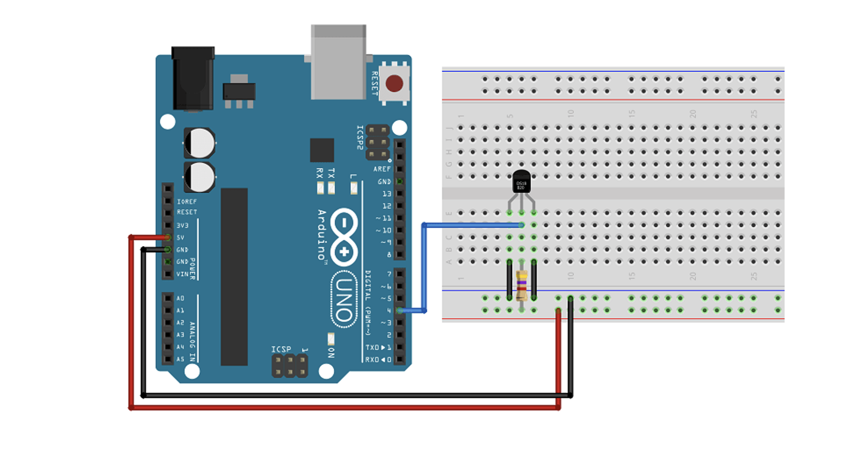
We need a temperature sensor DS18B20 with a 4.7kohm resistor for input, as output we have a dc fan.

           If the temperature is high the fan will turn on.

           If the temperature is low the fan is off.
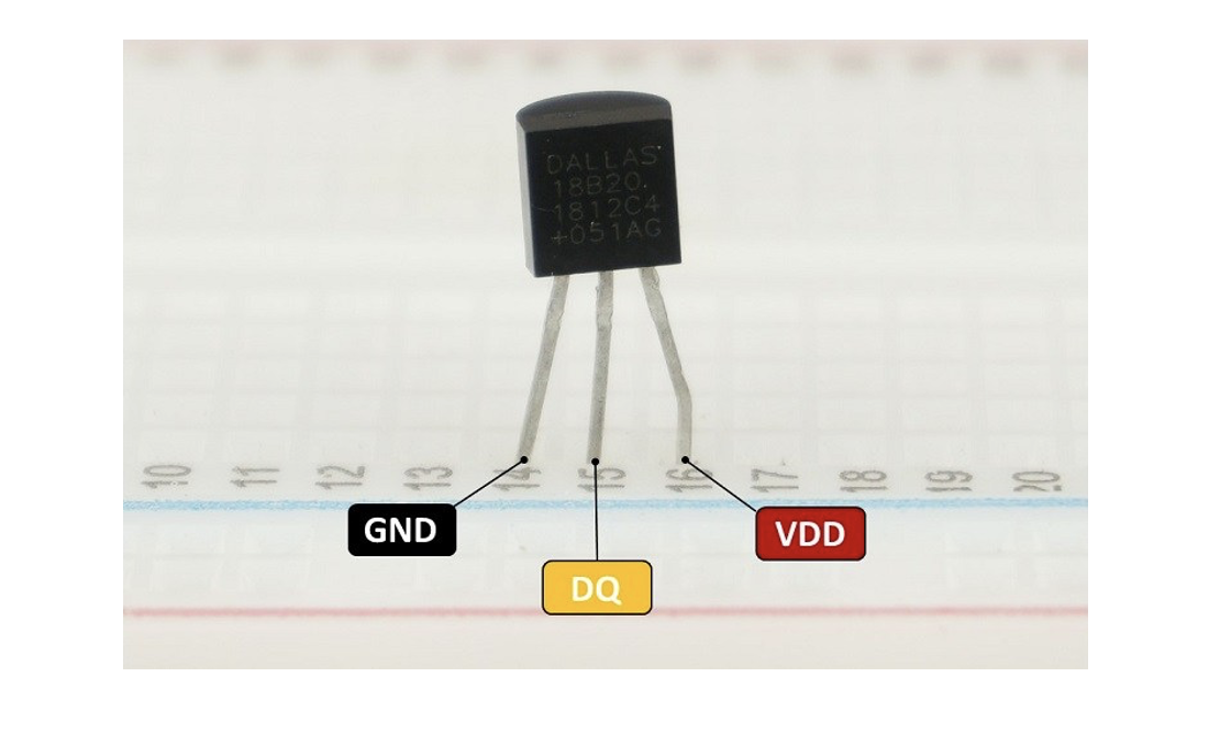
           Digital pin used is pin 5 for the temperature sensor

           Red led is to show if the temp above the limit.

           Redled is on pin 6
Code :
//code for temperature sensor


#include <OneWire.h>


#include <DallasTemperature.h>


#define ONE_WIRE_BUS temppin //pin in 4


OneWire oneWire(ONE_WIRE_BUS);


DallasTemperature sensors(&oneWire);


void setup()


{


  pinMode(redled, OUTPUT);


  Serial.begin(9600);


  //code for tempqrature


  sensors.begin();


}


void loop()


{


/********************************************************************/


//temperature sensor


sensors.requestTemperatures(); // Send the command to get temperature readings


Serial.println("Temperature is: ");


 celsius = sensors.getTempCByIndex(0);


Serial.print(celsius);


if(celsius>baselinetemp)digitalWrite(redled,HIGH);


else digitalWrite(redled,LOW);


}
STEPPER MOTOR :
The stepper motor used is a 5 V motor with a Stepper Motor with Driver (28BYJ-48 5V DC).
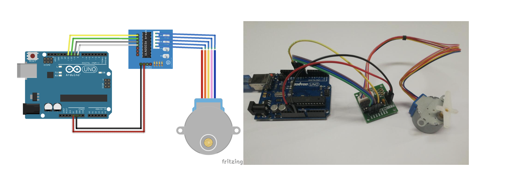
A stepper motor, much like a DC motor has a rotating permanent magnet propelled by stationary electrical magnets, however the motion is divided into a number of steps around the rotation of the rotating magnet. It does so by having several teeth on the rotating magnet that line up with specific locations around the stationary charged magnets. When voltage is supplied to a specific magnet or specific sequence of magnets the motor will rotate, or step to that position and hold.

Stepper motors can spin like a regular DC motor, however they can also stop on a position like a servo motor.
Code is using the library Stepper.h :
#include <Stepper.h>
// Define number of steps per rotation:
const int stepsPerRevolution = 2048;
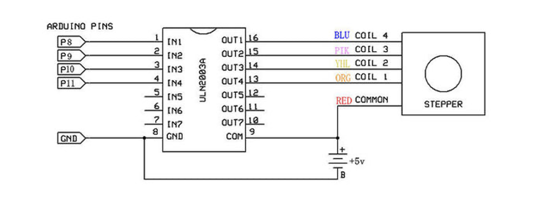
// Wiring:
// Pin 8 to IN1 on the ULN2003 driver
// Pin 9 to IN2 on the ULN2003 driver
// Pin 10 to IN3 on the ULN2003 driver
// Pin 11 to IN4 on the ULN2003 driver
// Create stepper object called 'myStepper', note the pin order:
Stepper myStepper = Stepper(stepsPerRevolution, 8, 10, 9, 11);
void setup() {
// Set the speed to 5 rpm:
myStepper.setSpeed(5);
// Begin Serial communication at a baud rate of 9600:
Serial.begin(9600);
}
void loop() {
// Step one revolution in one direction:
Serial.println("clockwise");
myStepper.step(stepsPerRevolution);
delay(500);
// Step one revolution in the other direction:
Serial.println("counterclockwise");
myStepper.step(-stepsPerRevolution);
delay(500);
}
Code Explanation:
The Stepper.h Arduino library is included in the first step of the project. On the website, you may learn more about this library.
// Include the Arduino Stepper.h library:
#include <Stepper.h>
Then we estimated how many steps it takes the motor to complete one rotation. We'll use the motor in full-step mode in this example. This translates to 2048 steps to complete a 360-degree rotation (see motor specifications above).
// Define number of steps per rotation:
const int stepsPerRevolution = 2048;
The next step is to build a new instance of the Stepper class, which represents a specific stepper motor that is attached to the Arduino. The function Stepper(steps, pin1, pin2, pin3, pin4) is used for this, where steps is the number of steps per revolution and pin1 through pin4 are the motor's pins. Set the pins in the following order to acquire the right step sequence: 8, 10,9,11.
// Create stepper object called 'myStepper', note the pin order:
Stepper myStepper = Stepper(stepsPerRevolution, 8, 10, 9, 11);
We labeled the stepper motor 'myStepper' in this example, but you could call it 'z motor' or 'liftmotor' instead. For example ,
Stepper liftmotor = Stepper(stepsPerRevolution, 8, 10, 9, 11);
Multiple stepper motor objects with distinct names and pins can be created. This makes it simple to control two or more stepper motors at once.

With the function, you may specify the speed in rpm in the setup by having
setSpeed(rpm).
At 5 V, a 28byj-48 stepper motor's maximum speed is around 10-15 rpm.
void setup() {
// Set the speed to 5 rpm:
myStepper.setSpeed(5);
// Begin Serial communication at a baud rate of 9600:
Serial.begin(9600);
}
We just call the step(steps) function in the loop part of code, which rotates the motor a certain number of steps at a speed defined by the function below
setSpeed(rpm)
Passing a negative value to this function causes the motor to spin in the opposite direction.
void loop() {
// Step one revolution in one direction:
Serial.println("clockwise");
myStepper.step(stepsPerRevolution);
delay(500);
// Step one revolution in the other direction:
Serial.println("counterclockwise");
myStepper.step(-stepsPerRevolution);
delay(500);
}
Source Used :
28byj-48-stepper-motor-arduino-tutorial
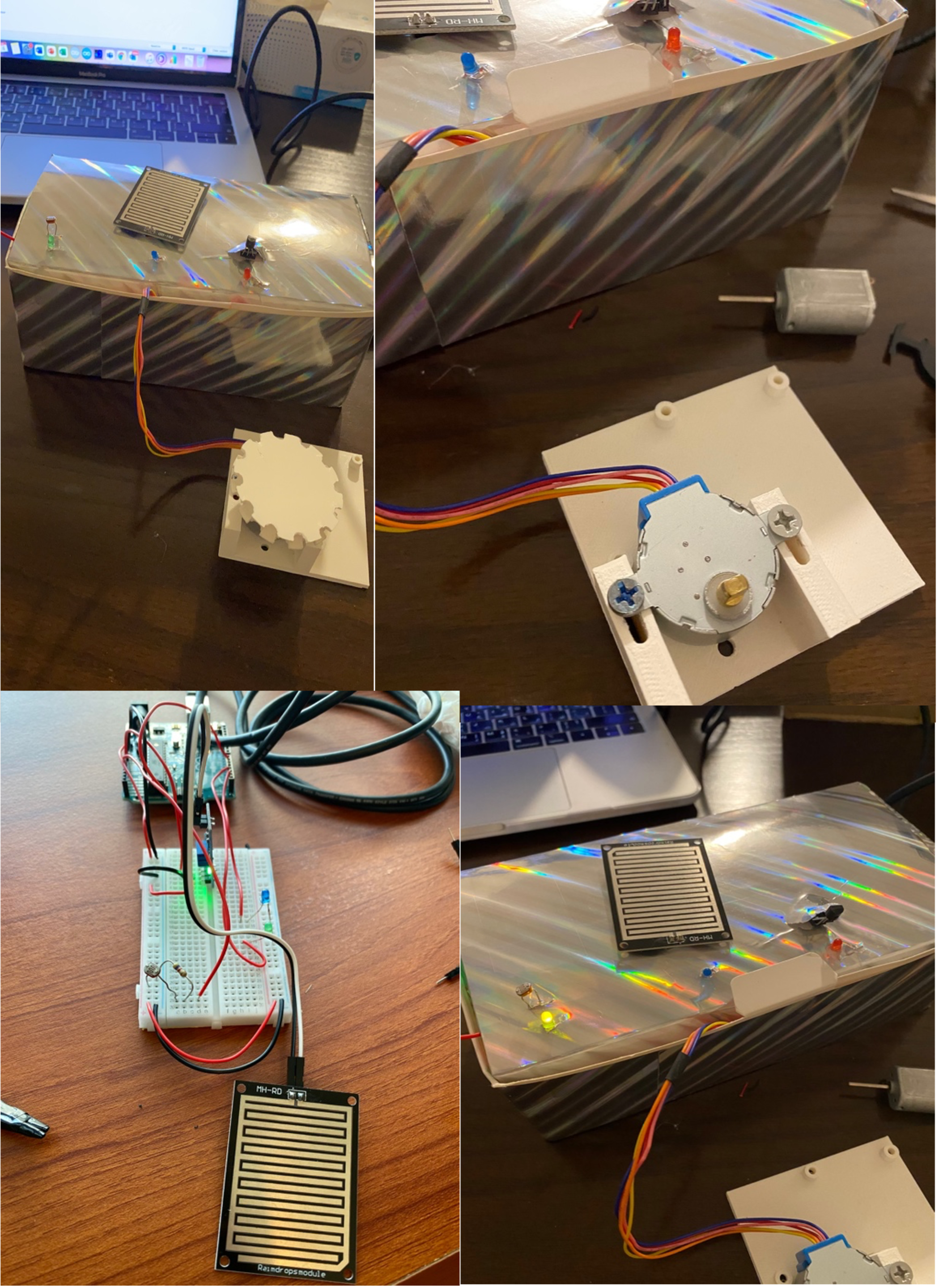
ASSEMBLY:
After having each sensor as input and component as outputs, we put everything together to assemble the project. For the processing code we based our code on the professors code :
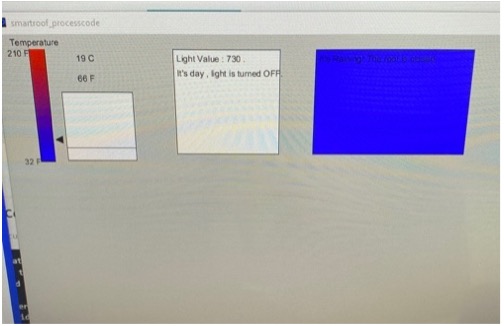
In order to send multiple values from the Arduino to processing, we kept the handshake and we read the values until having the new line. The processing is to display values on the screen of the temperature, the rain status, and the light status. We created rectangles to present each input. The background color of the rectangles changes in accordance to the value. If the rain is present, the rectangle of rain changes to blue color and displays the sentence “it’s raining”. If the temperature is high or low we can see it as a graph with history of the previous 30 values. The temperature is displayed in Celsius and in Farhranayt. The LDR shows the light value so the rectangle changes color to yellow when it is dark which indicates that the light is turned on. In other words, processing was our way to visualize the data coming from the Arduino.
CONNECTION:
The stepper Motor is connected to the cover that should close when it rains. In order to have the motor control the cover we assumed the cover has a roller controller like the one found in normal curtains. So, we designed the controller that could be fitted into the stepper motor and to the cable of the roller curtain. Once the stepper motor turns clockwise, it will close the cover and if it turns anti clockwise it will open the cover
The reference to have the piece for the roller curtain is on this tutorial found below ...
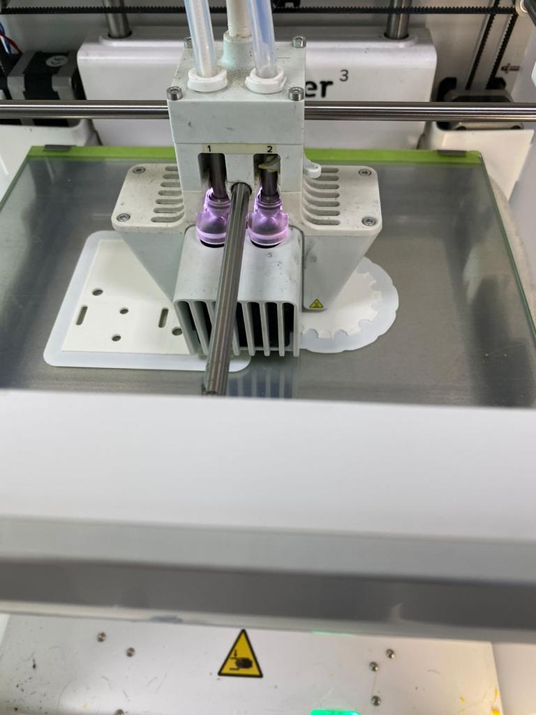
IMAGES OF OUR PROCEDURE :
The 3D printer that we used to print the pieces we made
The journey of making our brainstorming session come into reality by putting the hardware of Arduino to processing connection.
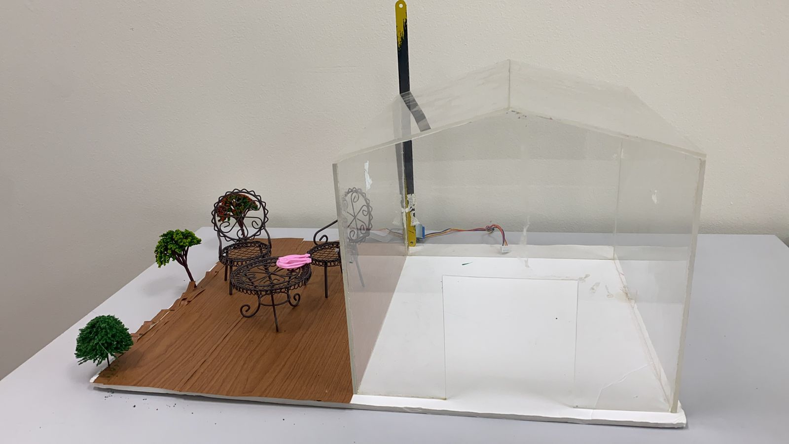
The doll sized house we are in the process of making to allow you a full experience
PROGRESS VIDEO :
USER TESTING VIDEO :
FEEDBACK FROM THE TESTER :
At first without explaining our project to him , he said he was not able to figure it out, like he cant make sense of what's being presented to him. However, after I gave the general instructions of what each shall do, and the whole project's concept, it made sense. He recommends us to create a brochure or a manual as a guidelines. Another thing he suggested is maybe connect our light sensor to an actual light bulb so it creates a more realistic experience or instead remove the other LEDs so only the light one has the impression of a light bulb as the others are technical. Last, but not least, his final comment was that cause our concept is based on an outdoor experience, it will be nice if after finishing our project we test it out in the daylight.
NEXT STEPS OF IMPROVING :
We would definitely try to either remove the other less or connect to a light bulb if it works with us, and other than that add the extra features that shall be there. For instance, we are still designing our doll size house and we still haven't done the temperature connection to the fan. Our main goal is to finish up with the actual features we shall have , and if we were able to finish all that, then we may consider either removing less or adding a light bulb as mentioned above.
PROCESSING FULL CODE:
//import Serial communication library
import processing.serial.*;
//init variables
Serial myPort;
int tempC;
int tempF;
int yDist;
int rainstatus;
int[] tempHistory = new int[100];
int ldrvalue;
void setup()
{
//set the size of the window
 size(800,600);
 printArray(Serial.list());
 String portname=Serial.list()[7];
 println(portname);

//init serial communication port
 myPort = new Serial(this, portname, 9600);
 myPort.clear();
 myPort.bufferUntil('\n');
//fill tempHistory with default temps
 for(int index = 0; index<100; index++)
 tempHistory[index] = 0;
}

void draw()
{
 //get the temp from the serial port
 //while (myPort.available() > 0)
 {

//refresh the background to clear old data
 background(123);
 //draw the temp rectangle
 colorMode(RGB, 160);  //use color mode sized for fading
 stroke (0);
 rect (49,120,22,162);
 //fade red and blue within the rectangle
 for (int colorIndex = 0; colorIndex <= 160; colorIndex++)
 {
 stroke(160 - colorIndex, 0, colorIndex);
 line(50, colorIndex + 120, 70, colorIndex + 120);
 }
//draw graph
 stroke(0);
 fill(255,255,255);
 //rect(90,180,100,100);
 rect(90,120,220,150);
 for (int index = 0; index<100; index++)
 {
 if(index == 99)
 tempHistory[index] = tempC;
 else
 tempHistory[index] = tempHistory[index + 1];
 point(90 + index, 280 - tempHistory[index]);
 }
//write reference values
 fill(0,0,0);
textAlign(RIGHT);
text("Temperature Value",180,80);
 text("210 F", 45, 130);
 text("32 F", 45, 287);
//draw triangle pointer
 yDist = int(260 - (160 * (tempC * 0.01)));
 stroke(0);
 triangle(75, yDist + 20, 85, yDist + 15, 85, yDist + 25);
//write the temp in C and F
 fill(0,0,0);
textAlign(LEFT);
 text(tempC + " C", 115, 137);
 tempF = ((tempC*9)/5) + 32;
 text(str(int(tempF)) + " F", 115, 165);

 text("Light Value",520,80);
 if(ldrvalue<400){
 fill(0,255,0);
 rect(475,120,220,150);
 fill(0,0,0);
 text("Light Value : "+ldrvalue + " .", 480,137);
 text("It's dark , light is turned ON. ", 480, 157);
 }
 else
 {fill(255,255,255);
 rect(475,120,220,150);
 fill(0,0,0);
 text("Light Value : "+ldrvalue + " .", 480, 137);
 text("It's day , light is turned OFF. ", 480, 157);}


  text("Rain Status",320,340);
 if(rainstatus==1){
   fill(0,0,255);
 rect(275,350,220,150);
 fill(0,0,0);
 text("It's Raining! The roof is closed." , 280,370);
 }
 else {fill(255,255,255);
 rect(275,350,220,150);
 fill(0,0,0);
 text("No rain ", 280,370);}

 }
}

void serialEvent(Serial myPort){

  String s=myPort.readStringUntil('\n');

  s=trim(s);

  if (s!=null){

    int values[]=int(split(s,','));

    if (values.length==3){

     // tempC=(int)map(values[0],0,1023,0, width);
tempC=values[0];
ldrvalue=values[1];
      rainstatus=values[2];

    }
      println(tempC,ldrvalue,rainstatus);

  myPort.write('0');

}

  }
ARDUINO FULL CODE :
const int capteur_D = 4;

const int capteur_A = A0;

int blueled=2;//for rain

int val_analogique;

int LDRsensorPin=A1;

int LDRsensorValue = 0;

int greenled = 3;//green light for ldr

int redled=6;

int temppin=5;

int baselinetemp=25;

int ldrvaluelimit=400;

int celsius=0;

bool closed=false;
int raining=0;
//code for stepper motor

#include <Stepper.h>

const int stepsPerRevolution = 2048;

Stepper myStepper(stepsPerRevolution, 8, 10,9, 11);


//code for temperature sensor

#include <OneWire.h>

#include <DallasTemperature.h>

#define ONE_WIRE_BUS temppin //pin in 4

OneWire oneWire(ONE_WIRE_BUS);

DallasTemperature sensors(&oneWire);


void setup()

{

  pinMode(capteur_D, INPUT);

  pinMode(capteur_A, INPUT);

  pinMode(blueled, OUTPUT);

  pinMode(greenled, OUTPUT);

  pinMode(redled, OUTPUT);


myStepper.setSpeed(10);


  Serial.begin(9600);

  //code for tempqrature

  sensors.begin();

//handshake

  Serial.println("0,0");

}


void loop()

{

  /********************************************************************/

  //rain sensor

if(digitalRead(capteur_D) == LOW)

  {

   // Serial.println("Digital value : wet");
   raining=1;
    delay(10);

    digitalWrite(blueled,HIGH);

    if(!closed){//Serial.println("close: turn counterclockwise");

    myStepper.step(stepsPerRevolution);

    delay(1000);

    closed=true;  }

  }

else

  {raining=0;
    //Serial.println("Digital value : dry");

    delay(10);

    digitalWrite(blueled,LOW);

   if(closed){

    //Serial.println("open: turn clockwise");

    myStepper.step(- stepsPerRevolution);

    delay(1000);

    closed=false;}

  }

val_analogique=analogRead(capteur_A);
 //Serial.println("Analog value for rain sensor : ");

//Serial.print(val_analogique);

// Serial.println("");

delay(500);

/********************************************************************/

//ldr sendor


 LDRsensorValue = analogRead(LDRsensorPin);

if(LDRsensorValue < ldrvaluelimit)

{

  /// Serial.println("LED light on");

   digitalWrite(greenled,HIGH);//Serial.print(LDRsensorValue);

   //delay(1000);

}

else {digitalWrite(greenled,LOW);//Serial.println("LED light off,LDR value:");Serial.print(LDRsensorValue);
}


/********************************************************************/

//temperature sensor

sensors.requestTemperatures(); // Send the command to get temperature readings

//Serial.println("Temperature is: ");

 celsius = sensors.getTempCByIndex(0);

if(celsius>baselinetemp)digitalWrite(redled,HIGH);

else digitalWrite(redled,LOW);


  delay(1000);

//processing code

Serial.print(celsius);
Serial.print(',');
Serial.print(LDRsensorValue);
Serial.print(',');
Serial.println(raining);
/*/
if(Serial.available()>0){
char state = Serial.read ( );    // Reading the data received and saving in the state variable

if(state == '1')             // If received data is '1', then turn on LED

{

digitalWrite (greenled, HIGH);

}

if (state == '0') {     // If received data is '0', then turn off led

digitalWrite (greenled, LOW);

}

}

delay(50);

 */

  }
REFERENCES:
https://create.arduino.cc/projecthub/MisterBotBreak/how-to-use-a-rain-sensor-bcecd9
https://create.arduino.cc/projecthub/SURYATEJA/automatic-street-light-controller-27159f
https://randomnerdtutorials.com/guide-for-ds18b20-temperature-sensor-with-arduino/
https://www.aranacorp.com/en/control-a-stepper-motor-with-arduino/
https://osoyoo.com/2017/07/10/arduino-lesson-stepper-motor/
https://www.makerguides.com/28byj-48-stepper-motor-arduino-tutorial/