What My Project Does:
For this project I used an RGB light and the temperature sensor to create a simplified version of a mood ring. When the user touches the temperature sensor, the sensor detects a certain temperature that correlates with an output RGB color that could be associated with someone’s mood. The red indicates that person is very warm, possibly happy, and energetic. Green indicate the person is stable, under normal conditions. Blue, finally, indicates the person is cold from air conditioning, or is just feeling bitter that day.
How I Did It:
I read up the Arduino site figure out how to get the temperature sensor to spit out a number that correlated with temperature. When I was able to find the code online on how to get an output number from the sensor, I found specific ranges to use when determining when the specific color would turn on.
The red color turns on when the output voltage reads above 0.80. The green turns on between 0.78 and 0.80. Finally, anything below 0.78 is blue. These are all correlated to temperatures between 24° and 26° Celsius.
For the temperature coding, essentially I used a code that would take a floated number retrieved from the A0 pinhole, and then that number, when multiplied by 0.004882814 (as I found online), produces the voltage number. Within my loop function, I assigned the variable ‘voltage’ to the voltage number received by the sensor. This number then, when subtracted from 0.5 and multiplied by 100 (again, as I found online), was the equivalent to degrees Celsius. I then had the voltage and degrees C° printed in order to find the ranges for the lighting and to make sure the sensor was outputting stable numbers. At one point, the sensor I was using overheated and started outputting the temperature as -25°, so when I changed it out for another sensor it worked fine.
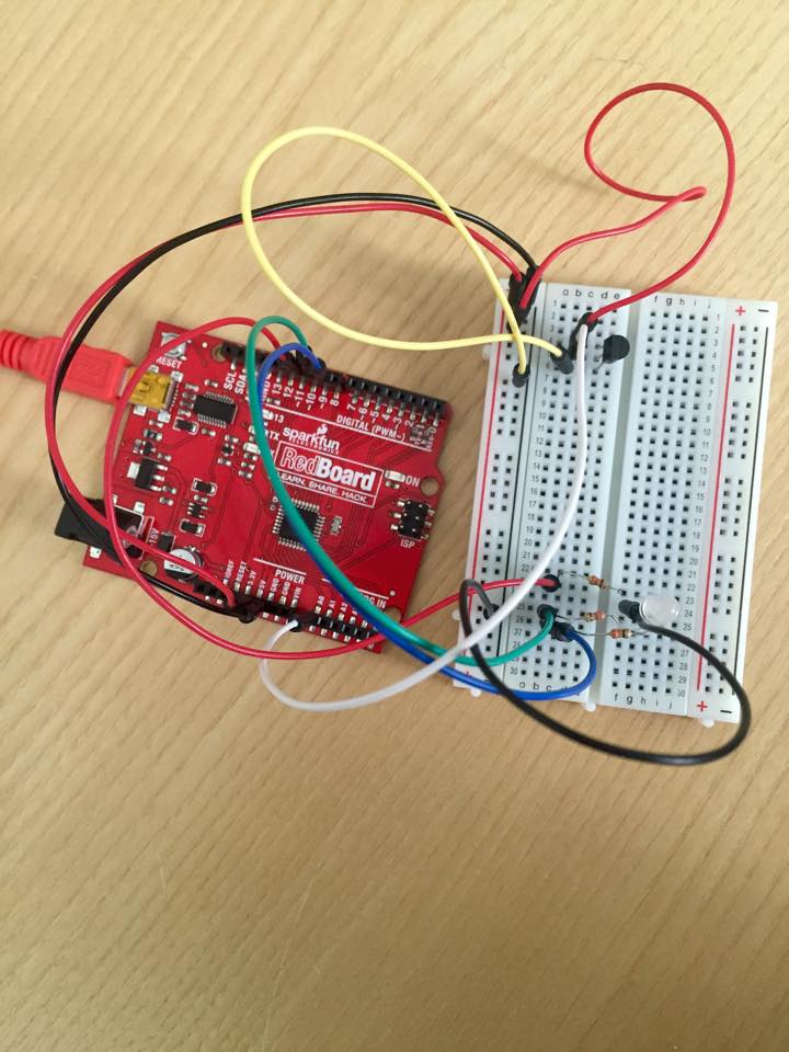
That’s a brief explanation of how the coding works. Below is the code with a few bits of commentary on what the coding means, followed by a video and set-up photo.
const int temperaturePin = 0;
int red = 11; //these correspond to the RGB pinholes
int green = 10;
int blue = 9;
void setup(){
  Serial.begin(9600); //For the sensor, this is the initial baud rate needed to match the speed of the code I'm running
  pinMode(red,OUTPUT);
  pinMode(green,OUTPUT);
  pinMode(blue,OUTPUT);

}
void loop() {
  float voltage, degreesC;

  voltage = getVoltage(temperaturePin); //(see below for the function that retrieves the voltage

  degreesC = (voltage - 0.5) * 100.0; //conversion of voltage to degrees

  Serial.print("voltage: "); //printing the voltage and corresponding degrees C
  Serial.print(voltage);
  Serial.print("  deg C: ");
  Serial.println(degreesC);
  delay(1000);

  if(voltage > 0.80){ //for warmer temperatures, the light turns on as red
  digitalWrite(red,HIGH);
  } else {
    digitalWrite(red,LOW);
  }
  if(voltage > 0.78 && voltage < 0.80){ //for stable room temperature, the light turns on green
    digitalWrite(green,HIGH);
  } else {
    digitalWrite(green,LOW);
  }
  if(voltage < 0.78){
    digitalWrite(blue,HIGH); //blue light for cooler temperatures
  } else {
    digitalWrite(blue,LOW);
  }

}

float getVoltage(int pin)   //This takes the A0 input and floats the number
{

 return (analogRead(pin) * 0.004882814); //the A0 number is multiplied by this to retrieve the voltage
}
Setup of RedBoard: