Introduction
The ANXIETI-E robot car is a wireless robot designed to perform both autonomous movements using object detection and edge detection, and manual control using radio control. This movement would be both controlled and reversed mapped to an interface in p5. The project aimed to create a robot that is capable of performing these functions while also being a fun and engaging project for me. The name, ANXIETI-E, was inspired by the robot WALL-E and the fact that the robot makes everyone anxious while operating over a table and moving toward the edge just before activating its edge detection.
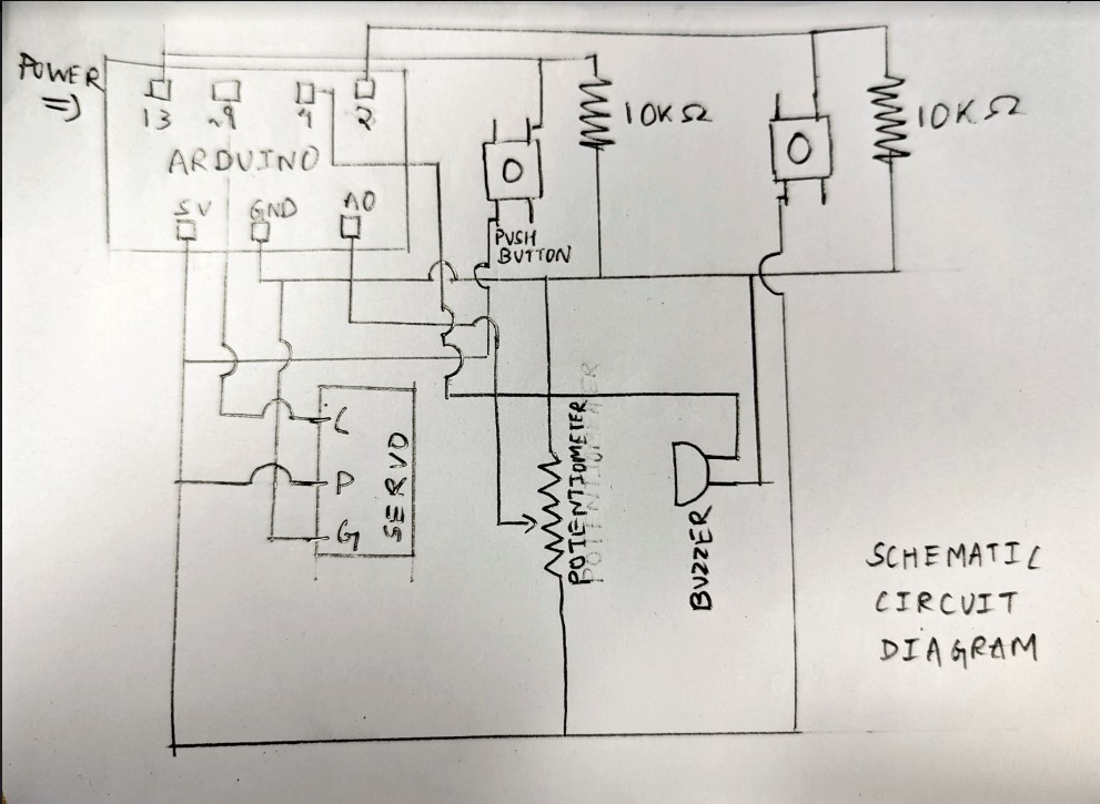
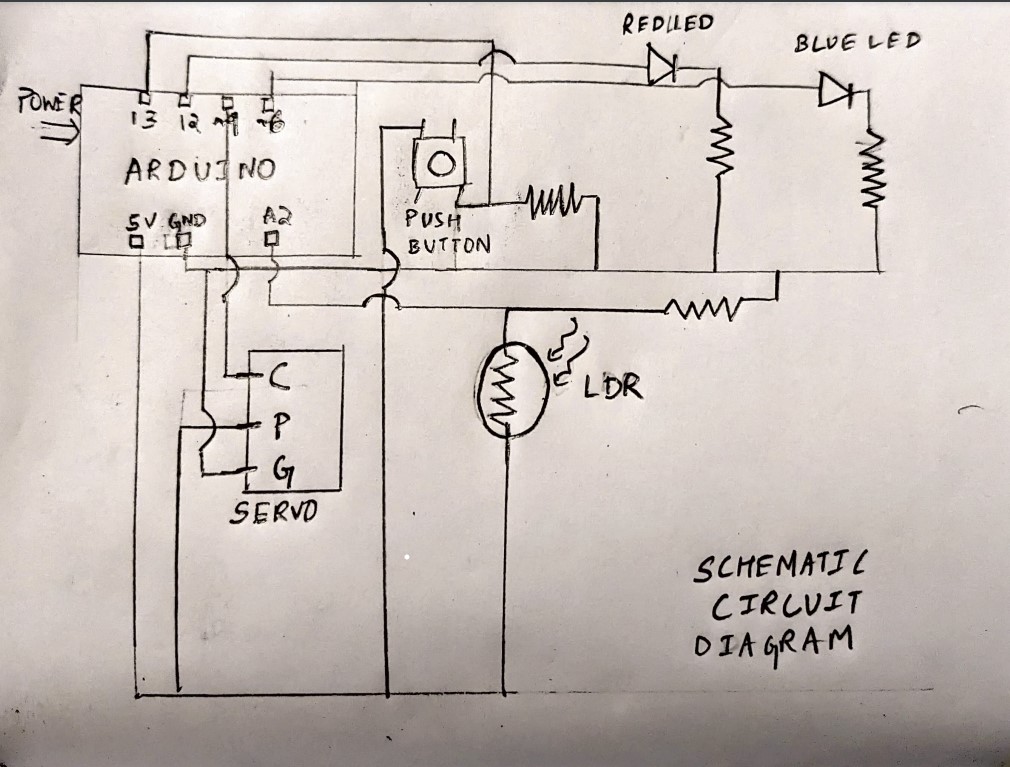
GitHub Code | P5JS Sketch | Schematic Diagram
Inspiration
The idea of creating ANXIETI-E robot car was born out of my desire to build a robot that could perform both autonomous and manual movements. I was inspired by the character WALL-E. This inspired me to create a robot that could capture the same spirit of adventure and fun while also being functional. Before submitting the proposal for my project, I spent some time watching YouTube videos on the power of Arduino and sensors. I was amazed by the wide range of possibilities that these components provided, and I knew that I could incorporate them into my robot car.
Concept and Interaction Design
The ANXIETI-E robot car is a wireless robot capable of both autonomous and manual control. The project consists of a p5 interface that allows the user to choose between these two modes. The p5 sketch connects to an Arduino using the serial port, and this Arduino communicates with another Arduino attached wirelessly to the robot car through radios. This communication route is also traced back to p5 to allow bidirectional communication.
When the user selects the autonomous mode, all the sensors work together to ensure the smooth and safe movement of the robot car. The robot car is equipped with several sensors and motors all working together to ensure that the robot moves smoothly and safely, avoiding obstacles and edges on its way. When the manual mode is activated, the user can control the robot directly using the arrow keys on their computer.
In both modes, as soon as a mode is selected, the robot enters a playground screen in p5 where p5 receives data back from the robot and then maps its movement on the screen. This allows the user to see the robot’s movement and trajectory in real time, giving them full control and understanding of the robot’s actions.
The project is a unique project that combines creativity, innovation, and technology to create a fun and functional robot car. The integration of p5, Arduino, and sensors allows for seamless communication and control between the user and the robot, making it an exciting and engaging project for anyone interested in robotics and technology.
Implementation (Challenges included)
The implementation of ANXIETI-E was a journey of constant iteration and improvement. Starting with a rough prototype, I gradually added sensors, integrated bidirectional wireless control, and implemented p5.js for the user interface. In this section, we will go through each component of the project in detail, outlining the challenges and solutions I encountered along the way. I will also outline the challenges I faced and the solutions I found for each, providing valuable insights for those looking to embark on similar projects in the future.
Rapid Prototyping
I found that rapid prototyping is an essential part of any product development process. It involves creating quick, rough versions of a product or system in order to test and refine its design. This approach allowed me to quickly iterate on my ideas and refine my designs based on the results of testing and feedback.
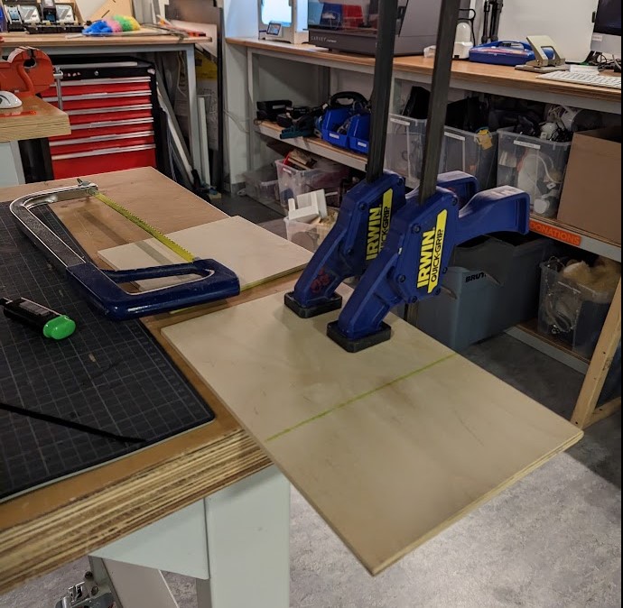
Building Frame
The exterior frame was built with wood. I was going through the materials in the IM lab and I found a piece of wood that felt like a pretty good size for the robot’s exterior. I scouted for another piece and found a little larger than the one I had. I took out the handsaw and made both pieces of the same size.
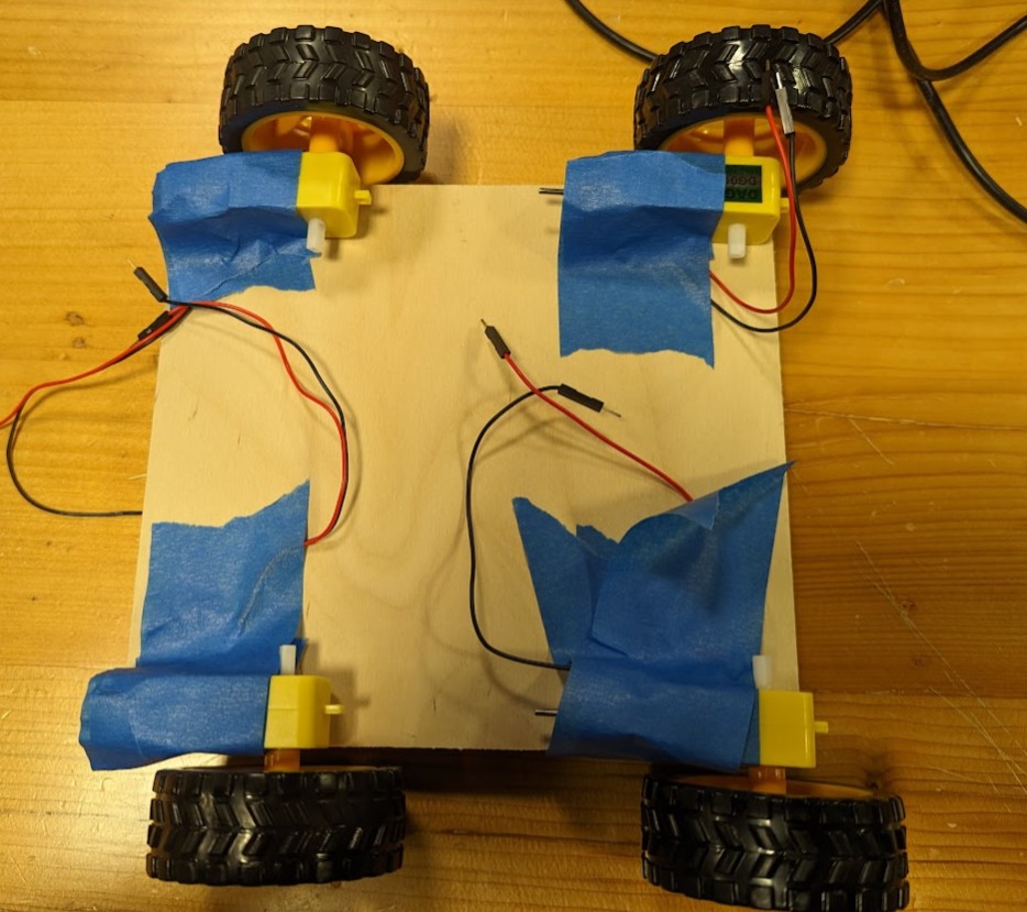
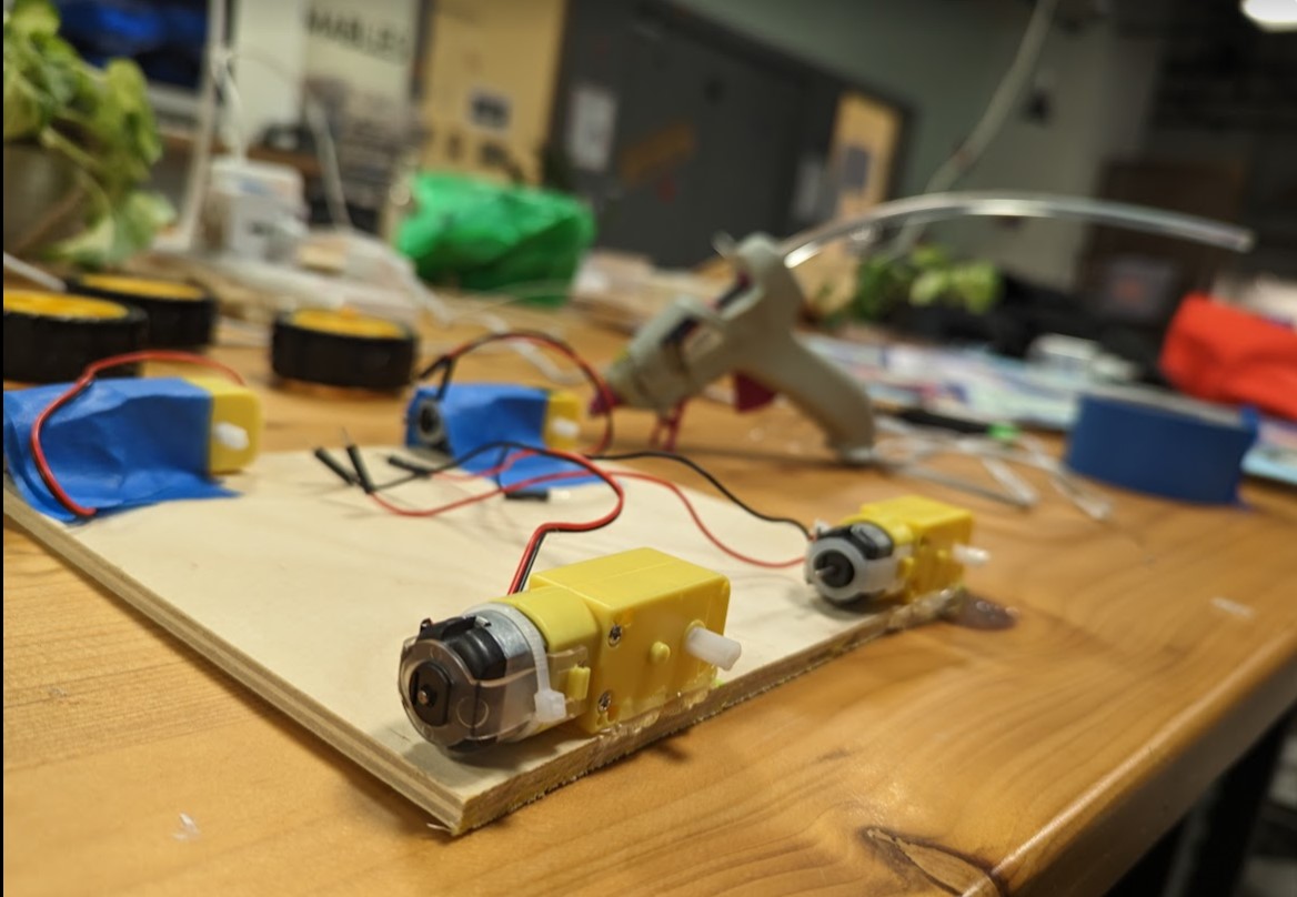
Setting Lower Level
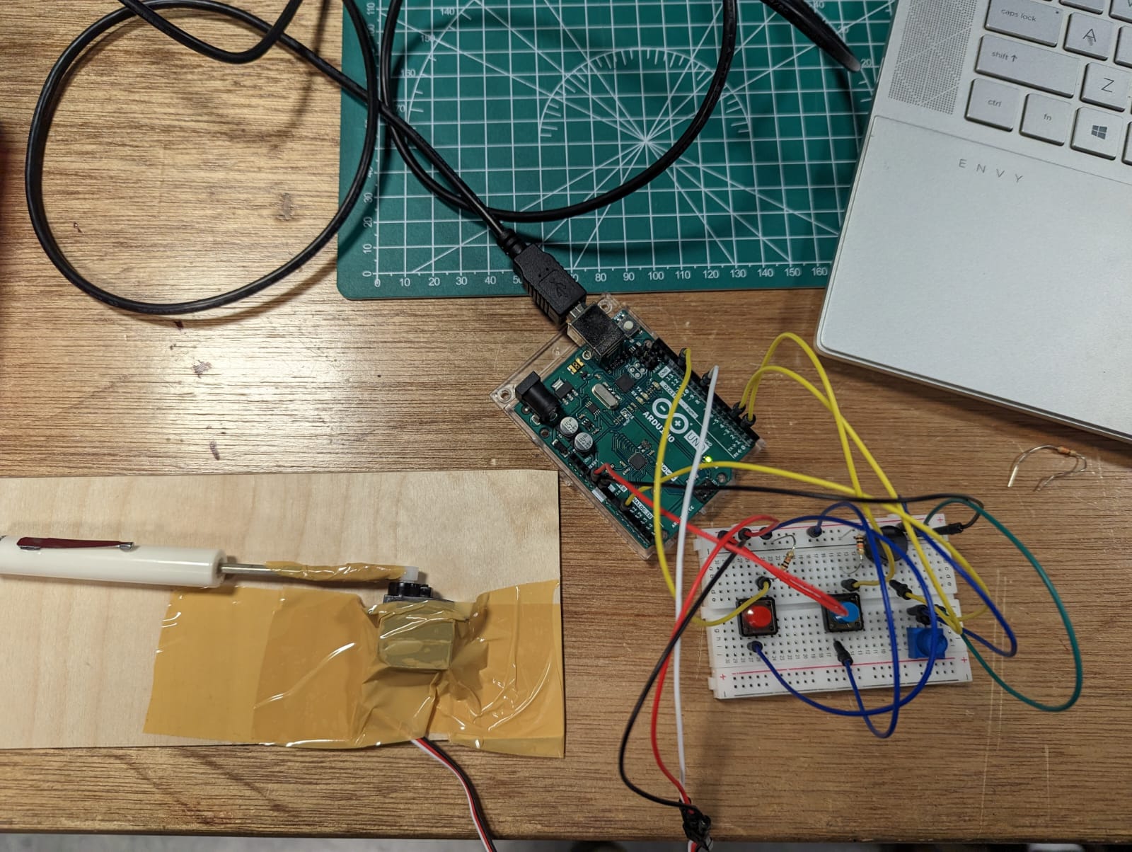
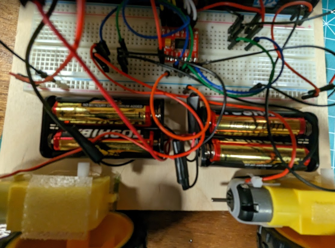
After I had both the pieces for the frame, I started setting the lower level by pasting the DC motors using tape and trying out different placements before committing to the final positioning. I even connected a small breadboard and motor driver and unit tested the DC motors by running a small piece of code to check if they were working fine in their placements. The code allowed me to test the movement of the car in different directions using input from the Serial monitor. I had attached 4 DC motors using a single motor driver by connecting the motors on one side together in parallel. This made sure that the robot was able to move in all 4 directions and at the same time ensured adequate current to all the four motors. After I made sure all the motors were working properly, I went forward to secure them in place using hot glue. I also added a bigger breadboard running along the middle of the lower level to facilitate easier connections.
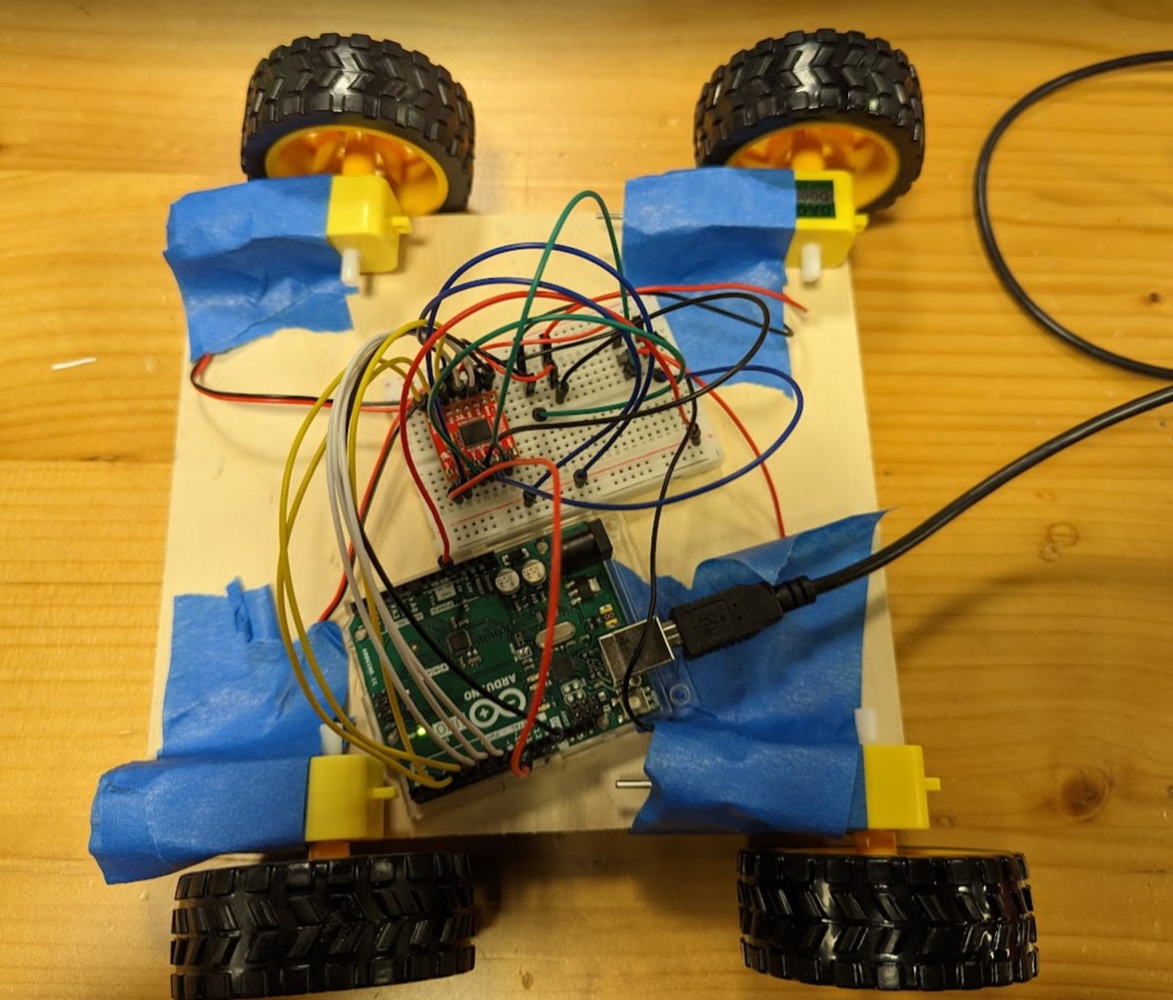
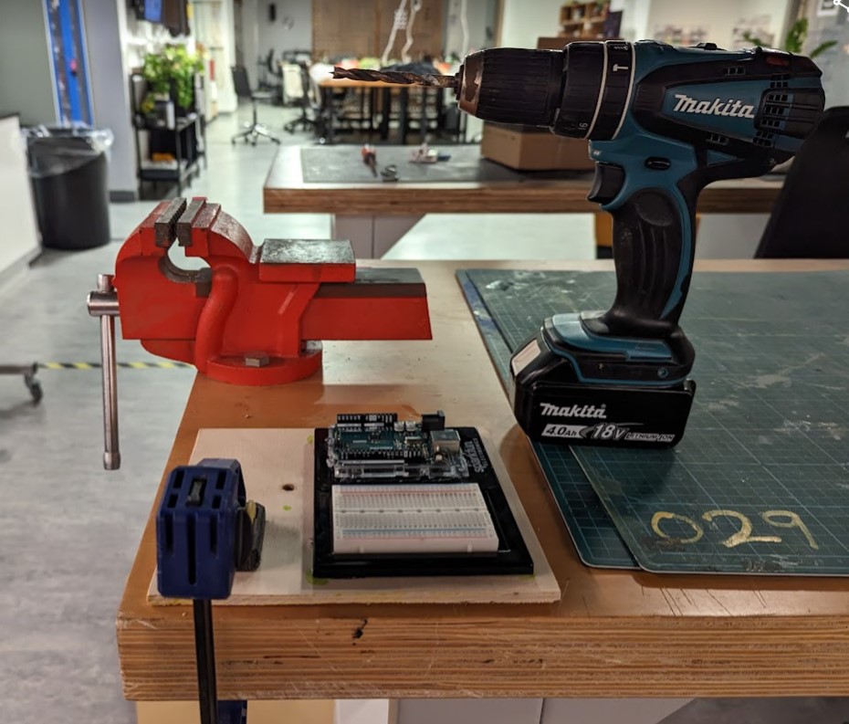
Setting upper level
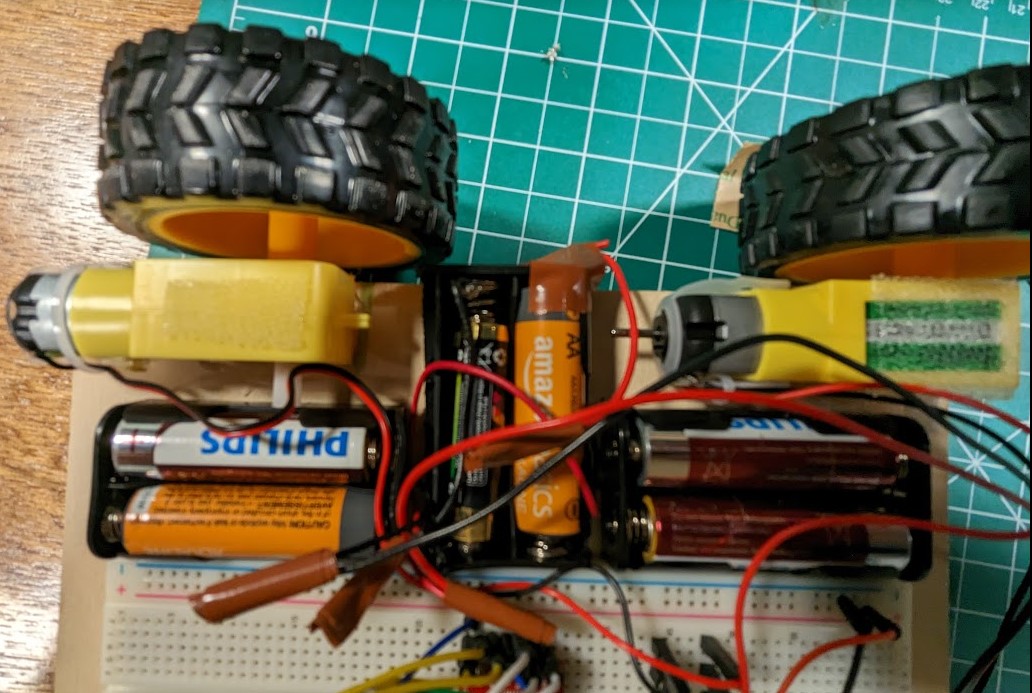
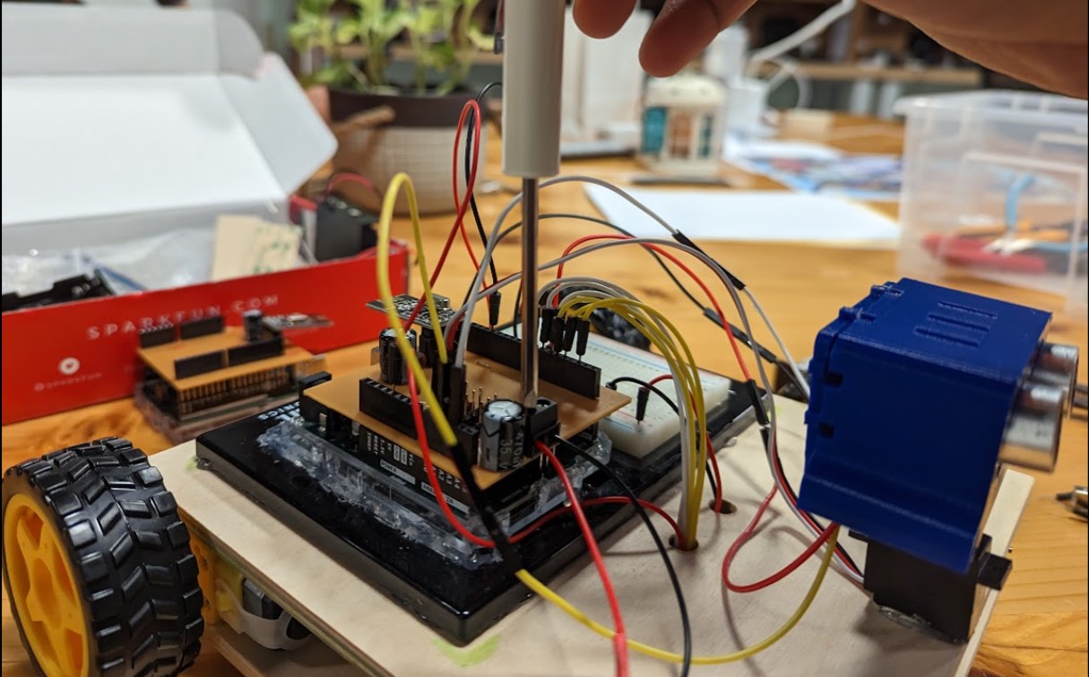
After setting the lower level, I started attaching the Arduino and another breadboard (smaller). I drilled some holes in the upper layer to let wires pass in easily. between both levels. I then used some velcro on top of the motors to attach both layers. This was essential as it allowed me to open and access the lower layers anytime for adding or changing connections.
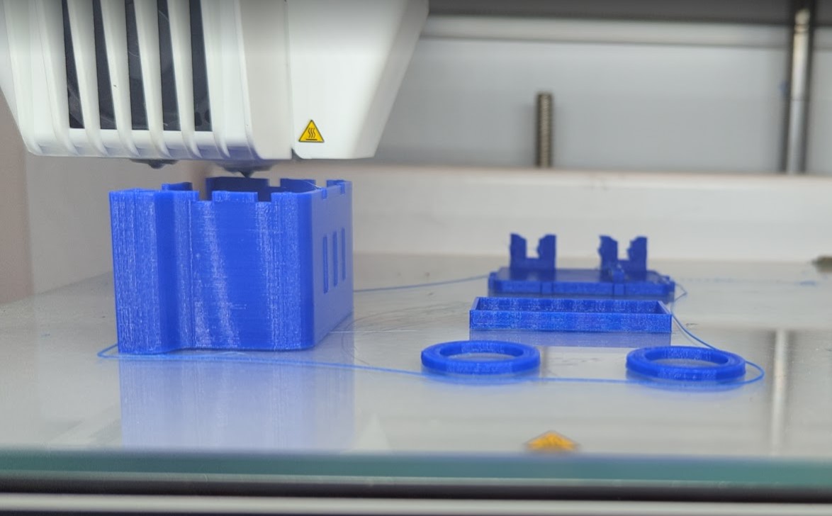
3D printing head
I was just really inclined on giving the robot a face and though about 3D printing a head for the distance sensor. I found this model on Thingiverse, sliced it using Cura and put it to print. I was really happy with the final result and people loved it!
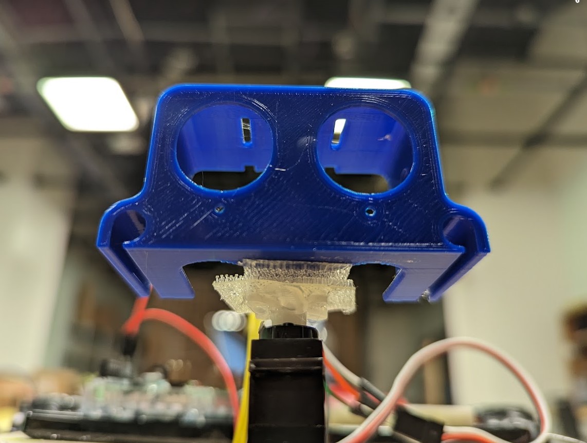
Integrating Servo
The next step involved attaching a Servo to the upper layer. I hot glue it to place. I now had to put the 3D-printed head onto it as it also functioned as the case for the distance sensor. This was a really tough job as the top of the servo was barely able to hold the case in place and anything I tried would fall off after a while. Finally, after a lot of failed attempts, I was able to use a combination of hot glue and velcro to securely strap the robot’s head on the servo. I then went on to unit test the servo to look right and left with a small piece of code.
Sensors and Wireless Communication
The next phase of the project was to integrate all the sensors, power, and wireless radios; and unit test them to make sure they are working properly individually. After they worked properly individually, they were combined to work together and then tested.
Integrating Distance Sensor – Collision Detection
To employ the collision detection mechanism, it was essential to use the data from the ultrasonic distance sensor. One challenge with this sensor is that the readings have a lot of noise in them. To filter this noise out, I implemented an exponential moving average filter that takes a weighted average of the new data while also putting in some weight to the previous data available. This made the sensor detect collisions much better.
The collision detection and avoidance mechanism was a -step process. The distance sensor keeps pinging the distance continuously. Whenever a collision is detected (which is when the reading from the distance sensor is less than the threshold set), the robot immediately stops and rolls back a bit. During the same time, the servo looks left and right and the distance sensor pings distance from both sides and evaluates which direction has an object that is farther away. Based on this computation, it decides to turn either left or right and move in that direction. If suppose the distance in both directions is still below the threshold, it continues to move back and re-compute the distance until it becomes more than the threshold set.
This video shows me unit testing the ultrasonic distance sensor and checking for collisions
Integrating Power
All this while, the Robot was running off by taking power from the laptop which provided it with a constant power source. The next step was to make it wireless. I faced a lots of challenges here and tried out a plethora of things before finally finding a proper solution with the guidance of Professor Shiloh. Initially when I had plugged in a 9v battery thinking it would be enough to supply the whole unit. But the robot started behaving eratically even though it felt like it was receiving more power than usual. This led me to shift the servo to a separate power channel of 6V. But the problem still didn’t get solved. Upon checking the power connections with a multimeter we realized that due to a larger internal resistance of the 9v battery, the board was only receiving a current of about 5v or less and was even dropping further. This led to the code getting resetted again and again and making the robot behave erratically. Upon consultation with Professor Shiloh, I decided to replace the 9v batter with 6 AA batteries on top of the 4 AA batteries that were already used by the servo. This made the total count of batteries to 10. Now, I had initially not accounted for these and hadn’t made enough space for so many battery holders. But with some careful placement (which also involved cutting up a 4 piece battery holder into 2) and a lot of soldering, I was finally able to place all the things in the lower layer itself and also made sure that nothing was causing problems with the DC motors or the wires.
Integrating Radio: One Way (Arduino – Arduino)
The next step was to make the robot wireless. I was able to implement this using two NRF24 radios and the RF24 library. The radio was unit tested by modifying the code provided by Professor Shiloh. After the unit testing was successful, one of the radios was integrated to the Arduino on top of the robot car. This was a specifically difficult process as the entire wiring had to changed to the radio shield and all the wires using pins 9-13 had to be shifted to the analog pins as the radio used up pins 9-13. The shield also supported a power channel for the servo and it made the process easier.
Integrating IR Distance Sensor – Edge Detection
Edge detection was one of the easiest things to implement. I knew it could be implemented using an IR distance sensor, cause their rays are much more concentrated (unlike the US distance sensor which sends out waves of signals). When I checked the IR sensor, it just worked with me barely writing any code. The integration was also smooth enough and so was the inclusion of the edge detection. The one problem that I faced here was the fact that the sensor is actually adjusted to its surrounding conditions and when I shifted places, the sensor needed to be physically recalibrated for edge detection using a screwdriver. This did happen to me in the exhibition setting causing me to manually calibrate the edge detection.
Integrating all sensors together
The final part was to integrate all the sensors and motors together to create the autonomous part of the robot (unidirectional for now). One important thing here was to make sure that there was no halt in the physical execution of the code due to arduino’s delay function so I designed a custom delay function that checked for difference in milliseconds and entered a while loop for that time period and allowed asynchronous detection by several sensors avoiding delays to cause problems in the overall execution.
This is how the code progressed. The radio receives a signal to enter autonomous mode. The DC motors start running to move the robot forward. Both the Ultrasonic distance sensor and the IR distance sensors keep recording data. If at any instant, the pinged distance by the US distance sensor comes below the threshold, the collision detection process is activated (as described in detail above). The same thing happens if any of the IR sensors start receiving a value of 1 detecting that an edge has been detected. The aftermath involves the robot stopping and moving back a few steps while the US distance sensor checks for safety and moves in the right direction.
The only unsolved issue here that remains is, since there are no sensors that are present in the back of the car, it can be a bit unsafe sometimes for the car to randomly roll backwards at edges and fall off causing damage.
p5.js Component +Integration
Creating the p5 interface and Integrating it with the arduino code had its own process and set of challenges but finally I was successful in doing it.
Basic Interface
To test the code I first had to create a simple interface with 2 rectangles (signifying the manual and autonomous mode) and another screen for the robot playground. This was a pretty simple interface (rather wireframe), but built for testing and didn’t have any graphics. This is the link to the sketch.
p5-Arduino-Arduino Integration (One way)
I took the template code by Professor Aaron Sherwood and Professor Michael Ang for one-way serial communication code between p5 Serial port and Arduino and combined it to the uni-directional radio communication code I had unit tested previously. This helped me setup a one way communication setup between the p5 canvas to the arduino connected to it using a serial port and this arduino was then able to transmit the message over to the other arduino present on the robot car.
Using this mechanism, I was able to send some messages from p5js and start controlling the basics of the robot like movement, directly from the p5 browser
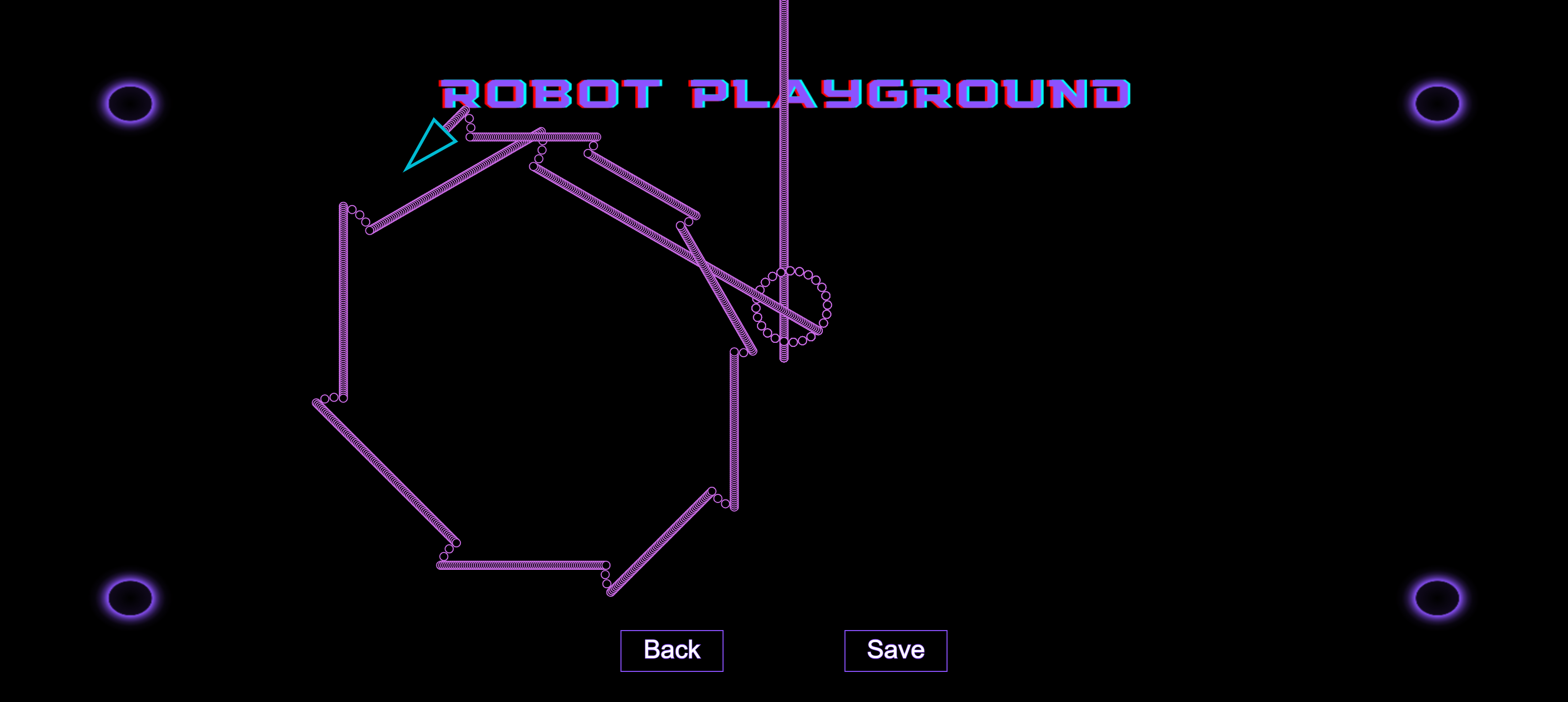
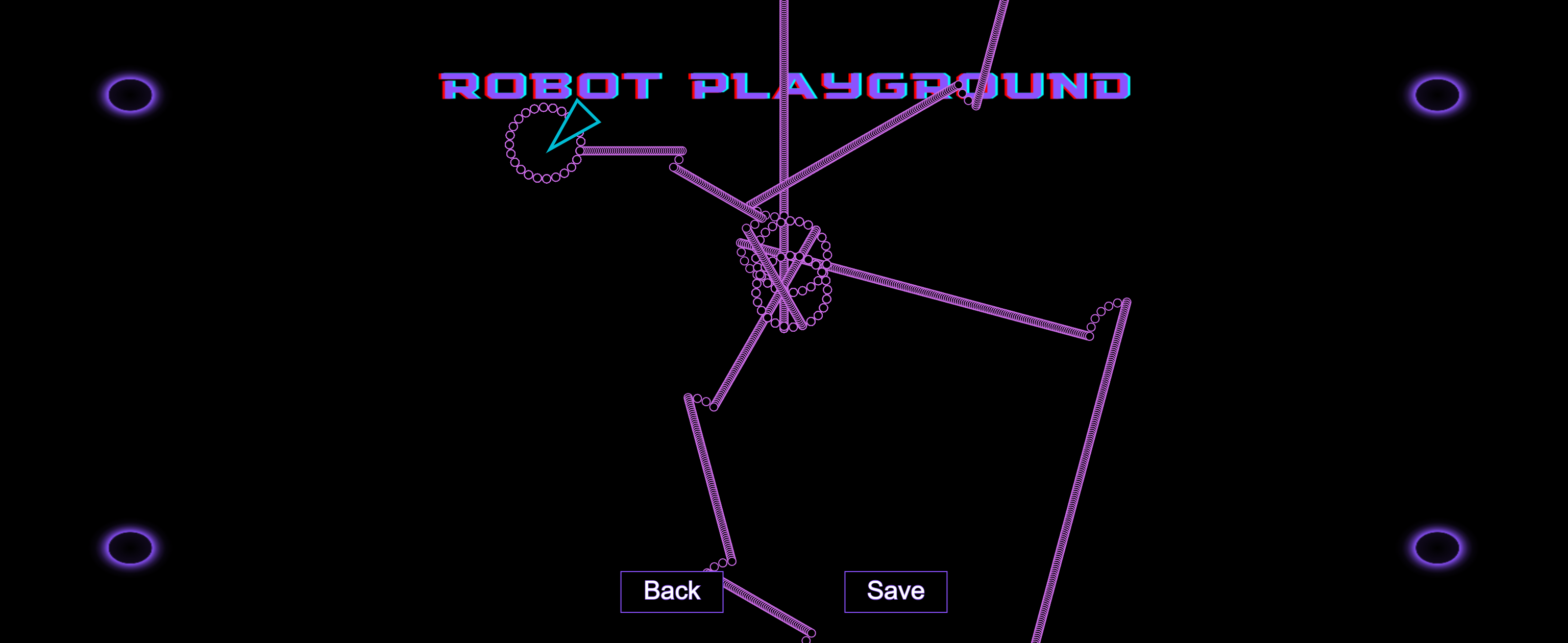
Creating Robot Playground
For the robot playground, I had an MSLogo Turtle sort of idea in mind. I started out by creating the code for the movement of the turtle. It was actually much more difficult than it felt initially, especially turning the triangle at specific angles. With some difficulty, I was finally able to control the turtle using the cursor (the direct arrow control was just for unit testing – the final version has the proper and better implementation). Then I went on to create a trail when the turtle moved. This trail was a trail of spheres. Whenever the turtle went off course, it started again from the center of the screen.
This is the code for the sketch.
Final Integration
The final phase of development included the implementation of a last few but very important features.
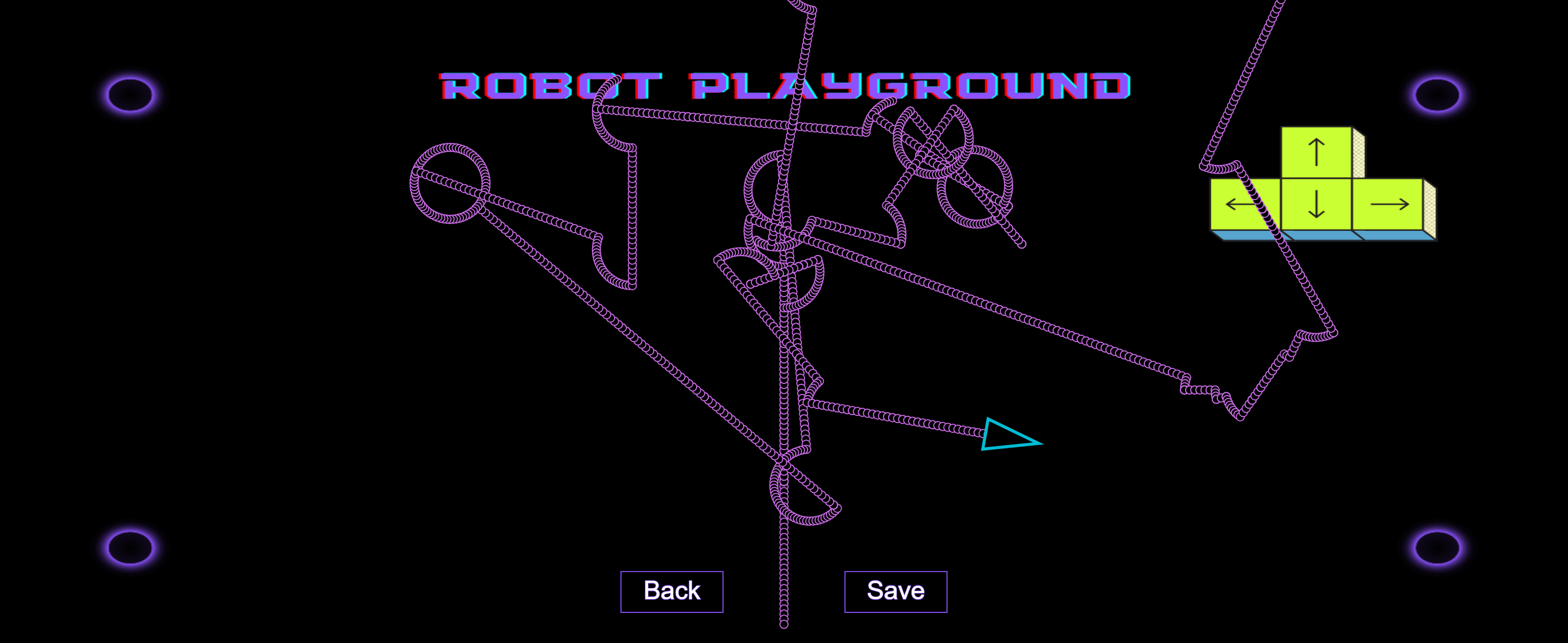
Advanced Interface – Autonomous and Manual
The first step in this phase was to create a properly functional and aesthetic interface. The flow of the website remained similar like the one I unit tested on, but this time it came with more instructions and better graphics. The second screen this time had one extra button over the back button. It was the save button that let the user save the canvas. This feature I felt would be pretty beneficial later when the reverse mapping worked.
This is the link to the initial sketch.
Manual Mode
Coding the manual mode was also important as it provided user the ability to control the robot just like any other RC car. The process was quite straightforward. I used one bit in the string to send command for “autonomous” or “manual” and then used the other bit to specify the direction based on the key that was pressed on p5. This way I was able to control the car remotely using the arrow keys of my computer.
Bidirectional Communication
Making the communication between the Arduino and p5 bidirectional was perhaps one of the most difficult tasks of the entire project. By the time I reached this part, I had already finished creating a unidirectional communication route between p5 and both the arduinos. I also had a bidirectional communication route between p5 and the arduino that was connected serially. The major problem that I faced was to make the radio communication bidirectional. Now the chip I used was capable of the but the implementation was tricky as the sender and receiver had to be continuously switched. This led to the big problem of packet losses and made the task quite difficult.
I employed several ways to mitigate this including switching in every loop, switching after success statements, switching after a fixed timeout interval or fixed number of retransmissions, etc. But all this just led to the increase in complexity of the program and barely helped with the objective.
Finally, I fiddled around with a code put up by Professor Shiloh, tried out several delay values, and was finally able to make the bidirectional communication thing work.
Final integration – Data Control and Reverse Mapping
After figuring out the bidirectional flow of information, the project was almost complete. I just had to stay set on a specific format of information exchange. I chose a string that consisted of 2 numbers separated by a comma. The data control schematic is as follows:
From p5 to arduino:
– 1st number is used to provide mode-selection information about whether autonomous or manual.
– 2nd number is used to provide direction-selection information about which direction to turn to – if the mode is manual.
Now there was a similar reverse mapping data flow, based on whose information, the trail of the robot was mapped on the p5 canvas.
From arduino to p5:
– 1st number provides the mode information and whether there was a collision or edge detection.
– 2nd mode provides the direction that the robot car takes after such a collision or edge detection.
Based on this information, both the robot and the reverse mapping on p5 were able to run smoothly.
Potential Future Developments
- Adding additional sensors for detection at the back of the robot
- Making the p5 interface even more aesthetic with more options for speed control as well.
- Finding a more permanent fix for the power issue.
- Giving the robot an even more polished look.
Reflections (Proud of!)
One of my proudest moments in the production phase was when I was finally able to set up the bidirectional communication between p5-Arduino-Arduino. It took me days and I had almost tried out everything to the point of giving up. I had a fallback code ready where I had to ditch the idea of reverse mapping data to p5. But I just didn’t wanna compromise with this feature and kept trying my best. And finally, it worked out!
Some of the other things that I feel very proud of even though they might seem small was the effort I put into the organization of the wires and connections in both layers and figuring out the best and most efficient use of space. I was able to create two floors of connections and kept the wires visible outside to a minimum. I fit in 10 AA batteries, 4 DC motors, and a long breadboard along with a large number of wires all in the lower level. I faced many challenges through the process of making the robot, but the one thing that never caused a problem was wrong connections or failing individual sensors. This was because I made sure to unit-test everything multiple times before moving on to the next feature. I also made sure the connections I made were quite secure by soldering and covering the ends later.
When I had initially written the proposal for the idea, it had felt very ambitious for a person working individually to be able to finish it before the deadline especially considering the complexity of the project. I was very prepared to leave some parts of if required. But somehow, by starting early and putting in a lot of time for the project every week, I was finally able to achieve everything I had promised in my initial proposal and more. It felt surreal to be presenting it in the IM showcase and I feel super proud of myself for the things that I have done and learned through the journey.
User Testing
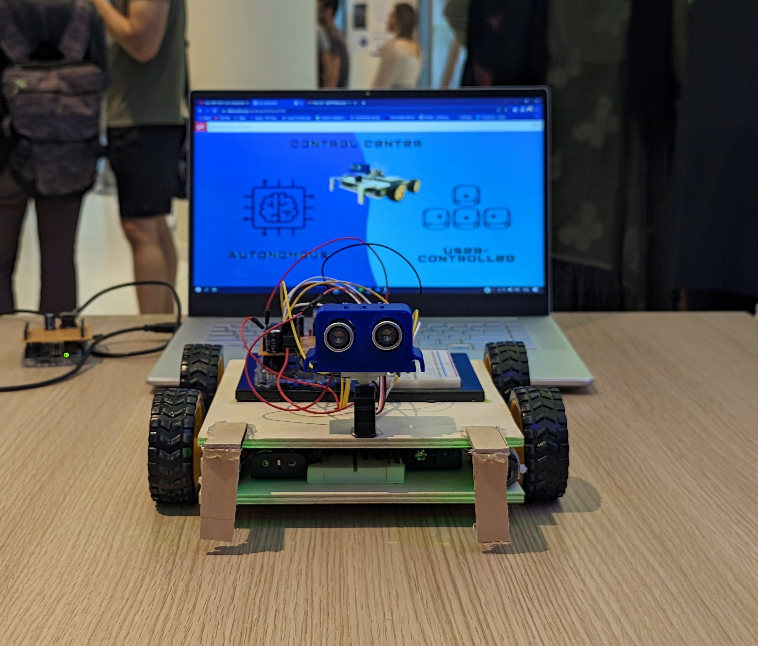
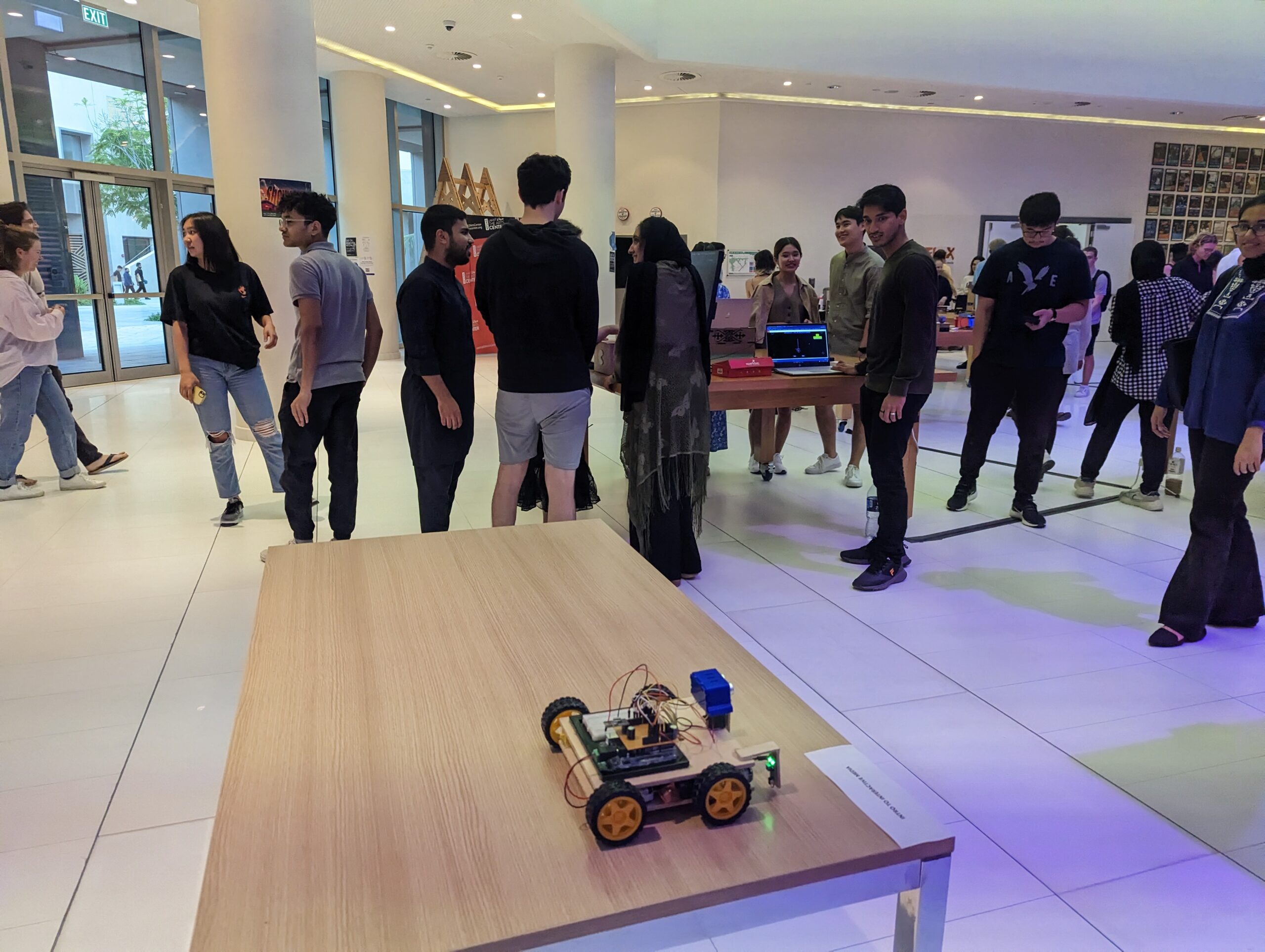
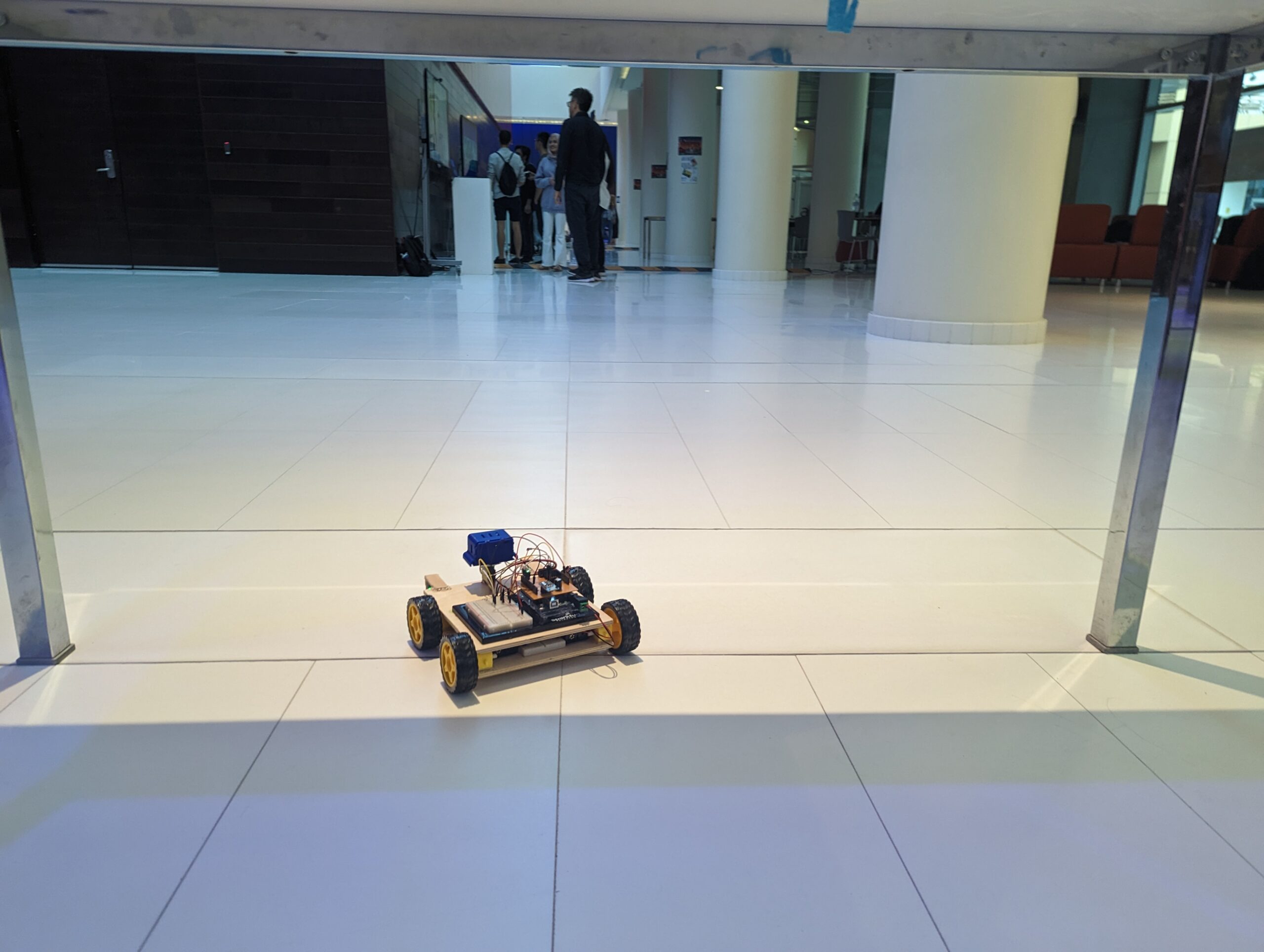
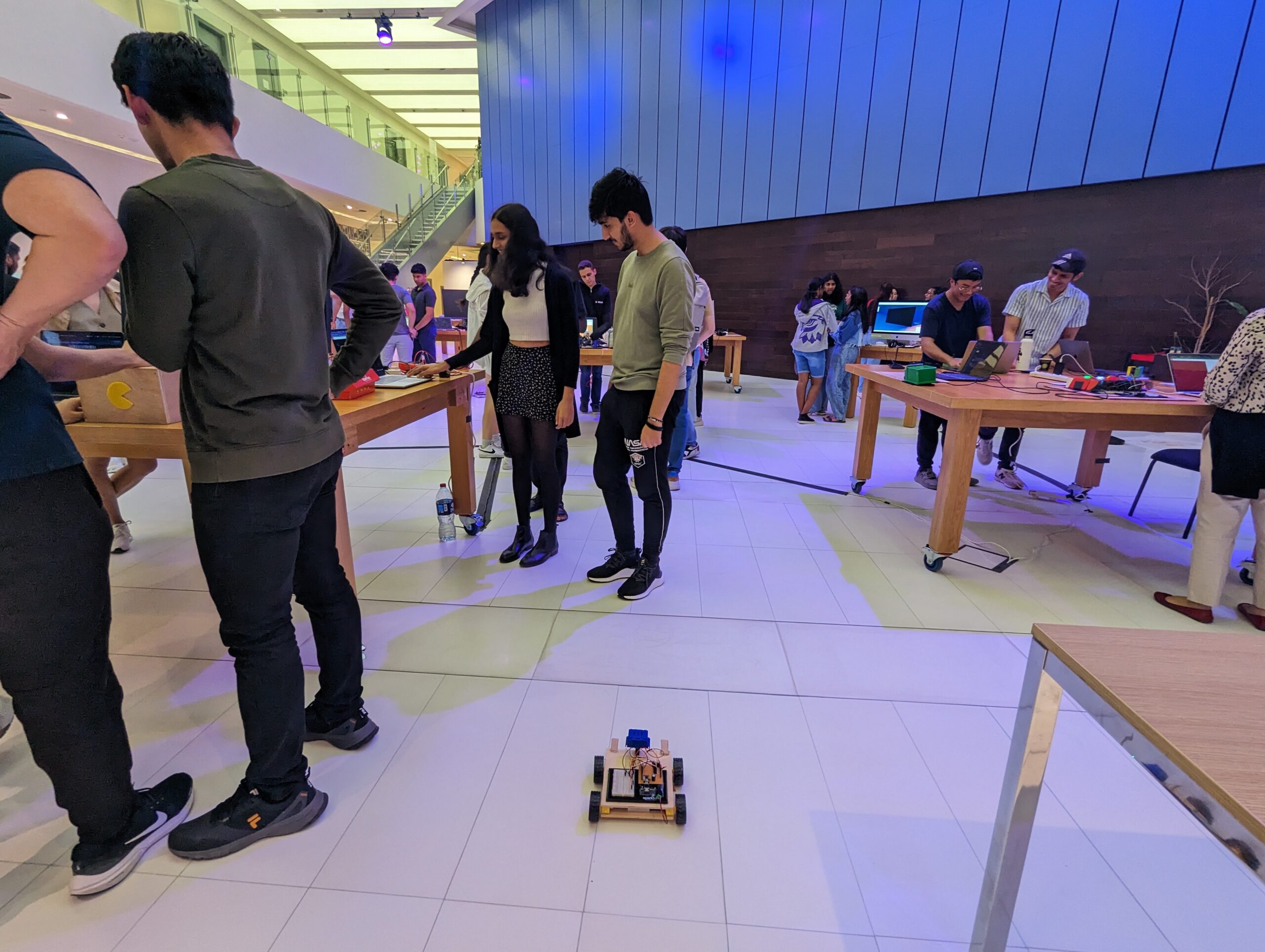
Exhibition
The project was presented at the NYU Abu Dhabi Interactive Media End-of-the-Semester Showcase. These are some of the pictures and videos from the exhibition.
Some canvas sketches created by people